US5633942A - Microphone mounting structure of a keyboard - Google Patents
Microphone mounting structure of a keyboard Download PDFInfo
- Publication number
- US5633942A US5633942A US08/705,804 US70580496A US5633942A US 5633942 A US5633942 A US 5633942A US 70580496 A US70580496 A US 70580496A US 5633942 A US5633942 A US 5633942A
- Authority
- US
- United States
- Prior art keywords
- microphone
- keyboard
- hole
- slide carrier
- supporting block
- Prior art date
- Legal status (The legal status is an assumption and is not a legal conclusion. Google has not performed a legal analysis and makes no representation as to the accuracy of the status listed.)
- Expired - Lifetime
Links
Images


Classifications
-
- G—PHYSICS
- G06—COMPUTING OR CALCULATING; COUNTING
- G06F—ELECTRIC DIGITAL DATA PROCESSING
- G06F3/00—Input arrangements for transferring data to be processed into a form capable of being handled by the computer; Output arrangements for transferring data from processing unit to output unit, e.g. interface arrangements
- G06F3/01—Input arrangements or combined input and output arrangements for interaction between user and computer
- G06F3/02—Input arrangements using manually operated switches, e.g. using keyboards or dials
- G06F3/0202—Constructional details or processes of manufacture of the input device
-
- B—PERFORMING OPERATIONS; TRANSPORTING
- B41—PRINTING; LINING MACHINES; TYPEWRITERS; STAMPS
- B41J—TYPEWRITERS; SELECTIVE PRINTING MECHANISMS, i.e. MECHANISMS PRINTING OTHERWISE THAN FROM A FORME; CORRECTION OF TYPOGRAPHICAL ERRORS
- B41J5/00—Devices or arrangements for controlling character selection
- B41J5/08—Character or syllable selected by means of keys or keyboards of the typewriter type
-
- H—ELECTRICITY
- H01—ELECTRIC ELEMENTS
- H01H—ELECTRIC SWITCHES; RELAYS; SELECTORS; EMERGENCY PROTECTIVE DEVICES
- H01H13/00—Switches having rectilinearly-movable operating part or parts adapted for pushing or pulling in one direction only, e.g. push-button switch
- H01H13/70—Switches having rectilinearly-movable operating part or parts adapted for pushing or pulling in one direction only, e.g. push-button switch having a plurality of operating members associated with different sets of contacts, e.g. keyboard
-
- H—ELECTRICITY
- H01—ELECTRIC ELEMENTS
- H01H—ELECTRIC SWITCHES; RELAYS; SELECTORS; EMERGENCY PROTECTIVE DEVICES
- H01H2239/00—Miscellaneous
- H01H2239/048—Miscellaneous comprising microphone or speaker
Definitions
- the present invention relates to computer keyboards, and relates more particularly to the microphone mounting structure of a computer keyboard which comprises a slide carrier slidably mounted in a horizontal bottom chamber of the top cover shell of the keyboard, and a microphone holder adjustably coupled to the slide carrier to hold a microphone between a horizontal position and a vertical position.
- the microphone mounting structure comprises a keyboard having defining a horizontal bottom chamber near the rear side and a plurality of equally spaced vertical locating grooves inside the horizontal bottom chamber, a slide carrier slidably mounted in the horizontal bottom chamber of the keyboard, the slide carrier having a pair of vertical locating ribs detachably forced into engagement with the vertical locating grooves of the keyboard, and a supporting block at the front side, the supporting block having a microphone holder mounting hole and two locating holes spaced at an angle around the microphone holder mounting hole, a microphone holder having a mounting rod coupled to the microphone holder mounting hole of the supporting block of the slide carrier, a locating rib forced into engagement with one locating hole of the supporting block of the slide carrier, and a plug hole spaced from
- FIG. 1 is an elevational view of the present invention showing the microphone holder and the microphone moved horizontally at the rear side of the keyboard;
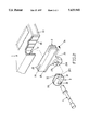
- FIG. 2 is an exploded view of the present invention
- FIG. 3 is a sectional assembly view of the present invention
- FIG. 4 is another sectional assembly view of the present invention when viewed from another angle.
- FIG. 5 shows a wire hole formed in the keyboard at one lateral side, and an electric cord inserted through the wire hole.
- a microphone mounting structure in accordance with the present invention is generally comprised of a keyboard 1, a slide carrier 2, a microphone holder 3, and a microphone 4.
- the keyboard 1 comprises a top cover shell 11.
- the top cover shell 11 of the keyboard 1 comprises a horizontal bottom chamber 12 near the rear side, and a plurality of equally spaced vertical locating grooves 13 respectively disposed in parallel inside the horizontal bottom chamber 12. Further, the keyboard 1 has a wire hole 14 at one lateral side through which the flexible electric cord 341 of the microphone 4 passes.
- the slide carrier 2 comprises a base block 20 slidably mounted in the horizontal bottom chamber 12, a pair of vertical locating ribs 21 bilaterally raised from the base block 20 at the back and adapted for engaging the vertical locating grooves 13 of the top cover shell 11 of the keyboard 1, an outward horizontal rib 22 raised from the front side at the bottom adapted for stopping at the bottom edge of the top cover 11, a supporting block 23 downwardly extending from the outward horizontal rib 22 through which the slide carrier 2 can be moved with the hand in the horizontal bottom chamber 12 to shift the vertical locating ribs 21 leftwards or rightwards between the vertical locating grooves 13, a through hole 231 at the supporting block 23 adapted for securing the microphone holder 3 and the microphone 4, and two locating holes 25 spaced for example at right angles around the through hole 231.
- the microphone holder 3 comprises a mounting rod 31 raised from one side and inserted into the through hole 231 of the slide carrier 23 and secured in place by threading a screw rod 24 into a screw hole 311 at the end of the mounting rod 31, a locating rib 32 disposed adjacent to the mounting rod 31 and adapted for engaging one locating hole 25 of the supporting block 23, a plug hole 33 spaced from the mounting rod 31 at right angles and adapted for holding the microphone 4, and a wire groove 35 at a suitable location for receiving the electric cord 341 of the microphone 4.
- the microphone holder 3 when in use, is turned in the through hole 231 of the supporting block 23 to force the locating rib 32 into one locating hole 25 of the supporting block 23, permitting the microphone 4 to be turned from a horizontal position (as shown in FIG. 3) to a vertical position (as shown in FIG. 1), and then the slide carrier 2 is moved in the horizontal bottom chamber 12 leftwards or rightwards to the desired location for picking up the user's voice (see FIG. 1).
Landscapes
- Engineering & Computer Science (AREA)
- General Engineering & Computer Science (AREA)
- Theoretical Computer Science (AREA)
- Human Computer Interaction (AREA)
- Physics & Mathematics (AREA)
- General Physics & Mathematics (AREA)
- Details Of Audible-Bandwidth Transducers (AREA)
- Push-Button Switches (AREA)
Abstract
Description
Claims (4)
Priority Applications (2)
| Application Number | Priority Date | Filing Date | Title |
|---|---|---|---|
| US08/705,804 US5633942A (en) | 1996-08-30 | 1996-08-30 | Microphone mounting structure of a keyboard |
| DE29615416U DE29615416U1 (en) | 1996-08-30 | 1996-09-04 | keyboard |
Applications Claiming Priority (2)
| Application Number | Priority Date | Filing Date | Title |
|---|---|---|---|
| US08/705,804 US5633942A (en) | 1996-08-30 | 1996-08-30 | Microphone mounting structure of a keyboard |
| DE29615416U DE29615416U1 (en) | 1996-08-30 | 1996-09-04 | keyboard |
Publications (1)
| Publication Number | Publication Date |
|---|---|
| US5633942A true US5633942A (en) | 1997-05-27 |
Family
ID=26059380
Family Applications (1)
| Application Number | Title | Priority Date | Filing Date |
|---|---|---|---|
| US08/705,804 Expired - Lifetime US5633942A (en) | 1996-08-30 | 1996-08-30 | Microphone mounting structure of a keyboard |
Country Status (2)
| Country | Link |
|---|---|
| US (1) | US5633942A (en) |
| DE (1) | DE29615416U1 (en) |
Cited By (6)
| Publication number | Priority date | Publication date | Assignee | Title |
|---|---|---|---|---|
| US5805709A (en) * | 1997-04-25 | 1998-09-08 | Liou; I-Chang | Desktop microphone base |
| US6166825A (en) * | 1998-12-14 | 2000-12-26 | Sienna Imaging, Inc. | Fiber channel data transfer with feedback control within a photographic process printer system |
| US6246570B1 (en) * | 1998-06-10 | 2001-06-12 | Samsung Electronics Co., Ltd. | Portable computer having a microphone |
| US6626704B1 (en) * | 2002-04-25 | 2003-09-30 | Daniel Pikel | Acoustic adapter device |
| US20070160228A1 (en) * | 2006-01-08 | 2007-07-12 | Fortemedia, Inc. | Audio signal input and output apparatus |
| US20070175313A1 (en) * | 2006-01-31 | 2007-08-02 | Kevin Vandervliet | MP3 player holder assembly |
Citations (2)
| Publication number | Priority date | Publication date | Assignee | Title |
|---|---|---|---|---|
| US5347630A (en) * | 1991-04-23 | 1994-09-13 | Seiko Epson Corporation | Computer system having a detachable display |
| US5438530A (en) * | 1992-12-28 | 1995-08-01 | Ing. C. Olivetti & C., S.P.A. | Portable electronic computer with tracking device |
-
1996
- 1996-08-30 US US08/705,804 patent/US5633942A/en not_active Expired - Lifetime
- 1996-09-04 DE DE29615416U patent/DE29615416U1/en not_active Expired - Lifetime
Patent Citations (2)
| Publication number | Priority date | Publication date | Assignee | Title |
|---|---|---|---|---|
| US5347630A (en) * | 1991-04-23 | 1994-09-13 | Seiko Epson Corporation | Computer system having a detachable display |
| US5438530A (en) * | 1992-12-28 | 1995-08-01 | Ing. C. Olivetti & C., S.P.A. | Portable electronic computer with tracking device |
Cited By (6)
| Publication number | Priority date | Publication date | Assignee | Title |
|---|---|---|---|---|
| US5805709A (en) * | 1997-04-25 | 1998-09-08 | Liou; I-Chang | Desktop microphone base |
| US6246570B1 (en) * | 1998-06-10 | 2001-06-12 | Samsung Electronics Co., Ltd. | Portable computer having a microphone |
| US6166825A (en) * | 1998-12-14 | 2000-12-26 | Sienna Imaging, Inc. | Fiber channel data transfer with feedback control within a photographic process printer system |
| US6626704B1 (en) * | 2002-04-25 | 2003-09-30 | Daniel Pikel | Acoustic adapter device |
| US20070160228A1 (en) * | 2006-01-08 | 2007-07-12 | Fortemedia, Inc. | Audio signal input and output apparatus |
| US20070175313A1 (en) * | 2006-01-31 | 2007-08-02 | Kevin Vandervliet | MP3 player holder assembly |
Also Published As
| Publication number | Publication date |
|---|---|
| DE29615416U1 (en) | 1996-10-24 |
Similar Documents
| Publication | Publication Date | Title |
|---|---|---|
| USD412162S (en) | Cradle for use with a handheld computer device | |
| USD416547S (en) | Docking device for portable computer | |
| USD346802S (en) | Headset | |
| USD434739S (en) | Portable telephone device | |
| USD416001S (en) | Handheld computer device | |
| USD408823S (en) | Telecommunications equipment enclosure | |
| US5568773A (en) | Multifunctional computer desk | |
| USD318473S (en) | Earphone earpiece | |
| USD410645S (en) | Mobile telephone | |
| USD450686S1 (en) | Communication system equipment enclosure | |
| USD361069S (en) | Stand for a portable telephone | |
| USD454980S1 (en) | Cord/cordless clipper | |
| USD442560S1 (en) | Pedestal housing for an equipment controller | |
| USD412319S (en) | Docking device for portable computer | |
| USD345974S (en) | Housing for a handset base | |
| USD358822S (en) | Holder for a portable telephone | |
| USD444121S1 (en) | Desktop charger | |
| USD426235S (en) | Cellular phone holder for use with laptop computer | |
| USD405786S (en) | Cordless headset telephone | |
| USD477829S1 (en) | Audio and stand accessory for an electronic device | |
| US5633942A (en) | Microphone mounting structure of a keyboard | |
| CA105476S (en) | Desk top charger | |
| USD435367S (en) | Computer desk | |
| USD341533S (en) | Portable electric hammer drill | |
| USD415998S (en) | Retractable cable device |
Legal Events
| Date | Code | Title | Description |
|---|---|---|---|
| AS | Assignment |
Owner name: SILITEK CORPORATION, TAIWAN Free format text: ASSIGNMENT OF ASSIGNORS INTEREST;ASSIGNOR:TERNG, JAY;REEL/FRAME:008176/0951 Effective date: 19960821 |
|
| STCF | Information on status: patent grant |
Free format text: PATENTED CASE |
|
| FEPP | Fee payment procedure |
Free format text: PAYOR NUMBER ASSIGNED (ORIGINAL EVENT CODE: ASPN); ENTITY STATUS OF PATENT OWNER: LARGE ENTITY |
|
| REMI | Maintenance fee reminder mailed | ||
| FPAY | Fee payment |
Year of fee payment: 4 |
|
| SULP | Surcharge for late payment | ||
| AS | Assignment |
Owner name: LITE-ON TECHNOLOGY CORPORATION, TAIWAN Free format text: MERGER;ASSIGNOR:SILITEK CORP.;REEL/FRAME:013887/0400 Effective date: 20021113 |
|
| FPAY | Fee payment |
Year of fee payment: 8 |
|
| FPAY | Fee payment |
Year of fee payment: 12 |
|
| REMI | Maintenance fee reminder mailed | ||
| FEPP | Fee payment procedure |
Free format text: PAYER NUMBER DE-ASSIGNED (ORIGINAL EVENT CODE: RMPN); ENTITY STATUS OF PATENT OWNER: LARGE ENTITY Free format text: PAYOR NUMBER ASSIGNED (ORIGINAL EVENT CODE: ASPN); ENTITY STATUS OF PATENT OWNER: LARGE ENTITY |
|
| AS | Assignment |
Owner name: EJT TECHNOLOGIES INC., SAMOA Free format text: ASSIGNMENT OF ASSIGNORS INTEREST;ASSIGNOR:LITE-ON TECHNOLOGY CORPORATION;REEL/FRAME:026587/0405 Effective date: 20110517 |