US5624290A - Seal arrangement for propeller shafts of ships - Google Patents

Seal arrangement for propeller shafts of ships Download PDF

Info

Publication number
US5624290A
US5624290A US08/560,006 US56000695A US5624290A US 5624290 A US5624290 A US 5624290A US 56000695 A US56000695 A US 56000695A US 5624290 A US5624290 A US 5624290A
Authority
US
United States
Prior art keywords
housing
disposed
support means
shaft
seal
Prior art date
Legal status (The legal status is an assumption and is not a legal conclusion. Google has not performed a legal analysis and makes no representation as to the accuracy of the status listed.)
Expired - Lifetime
Application number
US08/560,006
Inventor
Ernst-Peter Von Bergen
Gunter Pietsch
Current Assignee (The listed assignees may be inaccurate. Google has not performed a legal analysis and makes no representation or warranty as to the accuracy of the list.)
SKF Marine GmbH
Original Assignee
Blohm and Voss Holding AG
Priority date (The priority date is an assumption and is not a legal conclusion. Google has not performed a legal analysis and makes no representation as to the accuracy of the date listed.)
Filing date
Publication date
Family has litigation
First worldwide family litigation filed litigation Critical https://patents.darts-ip.com/?family=6462844&utm_source=google_patent&utm_medium=platform_link&utm_campaign=public_patent_search&patent=US5624290(A) "Global patent litigation dataset” by Darts-ip is licensed under a Creative Commons Attribution 4.0 International License.
Application filed by Blohm and Voss Holding AG filed Critical Blohm and Voss Holding AG
Priority to US08/560,006 priority Critical patent/US5624290A/en
Assigned to BLOHM + VOSS HOLDING AG reassignment BLOHM + VOSS HOLDING AG CHANGE OF NAME (SEE DOCUMENT FOR DETAILS). Assignors: BLOHM + VOSS AG
Application granted granted Critical
Publication of US5624290A publication Critical patent/US5624290A/en
Assigned to BLOHM + VOSS INDUSTRIE GMBH reassignment BLOHM + VOSS INDUSTRIE GMBH ASSIGNMENT OF ASSIGNORS INTEREST (SEE DOCUMENT FOR DETAILS). Assignors: BLOHM + VOSS HOLDING AG
Anticipated expiration legal-status Critical
Expired - Lifetime legal-status Critical Current

Links

Images

Classifications

    • BPERFORMING OPERATIONS; TRANSPORTING
    • B63SHIPS OR OTHER WATERBORNE VESSELS; RELATED EQUIPMENT
    • B63HMARINE PROPULSION OR STEERING
    • B63H23/00Transmitting power from propulsion power plant to propulsive elements
    • B63H23/32Other parts
    • B63H23/321Bearings or seals specially adapted for propeller shafts
    • BPERFORMING OPERATIONS; TRANSPORTING
    • B63SHIPS OR OTHER WATERBORNE VESSELS; RELATED EQUIPMENT
    • B63HMARINE PROPULSION OR STEERING
    • B63H5/00Arrangements on vessels of propulsion elements directly acting on water
    • B63H5/07Arrangements on vessels of propulsion elements directly acting on water of propellers
    • B63H5/08Arrangements on vessels of propulsion elements directly acting on water of propellers of more than one propeller
    • B63H5/10Arrangements on vessels of propulsion elements directly acting on water of propellers of more than one propeller of coaxial type, e.g. of counter-rotative type
    • BPERFORMING OPERATIONS; TRANSPORTING
    • B63SHIPS OR OTHER WATERBORNE VESSELS; RELATED EQUIPMENT
    • B63HMARINE PROPULSION OR STEERING
    • B63H21/00Use of propulsion power plant or units on vessels
    • B63H21/38Apparatus or methods specially adapted for use on marine vessels, for handling power plant or unit liquids, e.g. lubricants, coolants, fuels or the like
    • B63H21/386Apparatus or methods specially adapted for use on marine vessels, for handling power plant or unit liquids, e.g. lubricants, coolants, fuels or the like for handling lubrication liquids
    • FMECHANICAL ENGINEERING; LIGHTING; HEATING; WEAPONS; BLASTING
    • F16ENGINEERING ELEMENTS AND UNITS; GENERAL MEASURES FOR PRODUCING AND MAINTAINING EFFECTIVE FUNCTIONING OF MACHINES OR INSTALLATIONS; THERMAL INSULATION IN GENERAL
    • F16JPISTONS; CYLINDERS; SEALINGS
    • F16J15/00Sealings
    • F16J15/16Sealings between relatively-moving surfaces
    • F16J15/32Sealings between relatively-moving surfaces with elastic sealings, e.g. O-rings
    • F16J15/3204Sealings between relatively-moving surfaces with elastic sealings, e.g. O-rings with at least one lip
    • F16J15/3224Sealings between relatively-moving surfaces with elastic sealings, e.g. O-rings with at least one lip capable of accommodating changes in distances or misalignment between the surfaces, e.g. able to compensate for defaults of eccentricity or angular deviations
    • BPERFORMING OPERATIONS; TRANSPORTING
    • B63SHIPS OR OTHER WATERBORNE VESSELS; RELATED EQUIPMENT
    • B63HMARINE PROPULSION OR STEERING
    • B63H5/00Arrangements on vessels of propulsion elements directly acting on water
    • B63H5/07Arrangements on vessels of propulsion elements directly acting on water of propellers
    • B63H5/08Arrangements on vessels of propulsion elements directly acting on water of propellers of more than one propeller
    • B63H5/10Arrangements on vessels of propulsion elements directly acting on water of propellers of more than one propeller of coaxial type, e.g. of counter-rotative type
    • B63H2005/106Arrangements on vessels of propulsion elements directly acting on water of propellers of more than one propeller of coaxial type, e.g. of counter-rotative type with drive shafts of second or further propellers co-axially passing through hub of first propeller, e.g. counter-rotating tandem propellers with co-axial drive shafts
    • BPERFORMING OPERATIONS; TRANSPORTING
    • B63SHIPS OR OTHER WATERBORNE VESSELS; RELATED EQUIPMENT
    • B63HMARINE PROPULSION OR STEERING
    • B63H23/00Transmitting power from propulsion power plant to propulsive elements
    • B63H23/32Other parts
    • B63H23/321Bearings or seals specially adapted for propeller shafts
    • B63H2023/323Bearings for coaxial propeller shafts, e.g. for driving propellers of the counter-rotative type
    • BPERFORMING OPERATIONS; TRANSPORTING
    • B63SHIPS OR OTHER WATERBORNE VESSELS; RELATED EQUIPMENT
    • B63HMARINE PROPULSION OR STEERING
    • B63H23/00Transmitting power from propulsion power plant to propulsive elements
    • B63H23/32Other parts
    • B63H23/321Bearings or seals specially adapted for propeller shafts
    • B63H2023/327Sealings specially adapted for propeller shafts or stern tubes
    • YGENERAL TAGGING OF NEW TECHNOLOGICAL DEVELOPMENTS; GENERAL TAGGING OF CROSS-SECTIONAL TECHNOLOGIES SPANNING OVER SEVERAL SECTIONS OF THE IPC; TECHNICAL SUBJECTS COVERED BY FORMER USPC CROSS-REFERENCE ART COLLECTIONS [XRACs] AND DIGESTS
    • Y10TECHNICAL SUBJECTS COVERED BY FORMER USPC
    • Y10STECHNICAL SUBJECTS COVERED BY FORMER USPC CROSS-REFERENCE ART COLLECTIONS [XRACs] AND DIGESTS
    • Y10S277/00Seal for a joint or juncture
    • Y10S277/907Passageway in rod or shaft

Definitions

  • This invention generally relates to a seal arrangement for propeller drives for ships. More particularly, the seal arrangement of the present invention relates to a seal arrangement for being disposed between two concentric propeller shafts rotating in opposite directions.
  • Such seal arrangements for propeller drives for ships with two concentric propeller shafts rotating in opposite directions from one another generally have a seal for the outer shaft, sealing the outer shaft to the ships hull, and a seal for the inner shaft, sealing the inner shaft to the outer shaft.
  • Such seals can be designed as lip seals, wherein the seals are connected to the stern tube of the outer shaft in a water-tight manner.
  • the object of the invention is to overcome the problems resulting from fluctuations between the shafts, and accordingly refine a seal arrangement of the type described above so that complete compensation for the above-mentioned clearance fluctuations can be achieved.
  • a seal arrangement wherein the inner shaft seal is preferably supported by a housing ring, which in turn is preferably connected to the stern tube of the outer shaft in a fluid-tight manner.
  • the stern tube of the outer shaft can preferably have a supporting ring disposed thereabout and concentric to the housing ring.
  • This supporting ring represents a connecting element for a fluid-tight connection to the external shaft.
  • the housing ring can be connected to the supporting ring, and can be maintained at a radial distance from the supporting ring, by means of at least one elastic ring wall disposed therebetween. Such elastic ring walls can prevent fluid penetration.
  • the present invention also provide other numerous advantageous embodiments, for achieving the object of the invention.
  • a simple and effective solution for the watertight connection of the ring walls to each of the housing ring and the supporting ring can be provided by clamping the edges of the ring walls between adjacent ring elements, or clamping rings.
  • Additional embodiments of the present invention provide advantageous solutions for preventing axial excursions of the housing ring and thus of the lip seals.
  • One simple solution for preventing any axial excursions of the housing ring can be achieved by means of a guide.
  • One type of guide can preferably be configured as a ring-shaped groove, or hole, in the supporting ring, into which groove, or hole, a corresponding projection of the housing ring can project.
  • a second type of guide can be provided by a ring-shaped groove, or hole, in the housing ring in the vicinity of the friction bearing.
  • the inner shaft can then be provided with a bearing bush which projects into the groove of the housing ring.
  • the present invention also provides a simple means to effectively lubricate the friction bearing and the lip seals simultaneously with oil.
  • a lubricant caused to circulate by means of a pressure can be provided for the friction bearing.
  • an oil feed to the friction bearing can be provided by means of a lubrication passage disposed inside the inner shaft, and an oil return passage can be provided in the housing ring for providing a return flow of the lubricating oil.
  • the seal arrangement according to the present invention is also adaptable to the increased requirements for a reliable seal at high pressures of the medium to be sealed out, as well as the requirements relating to operational safety and reliability and environmental protection. This can be done by providing a multiple lip seal with two or more lip seals located behind one another and at some distance from one another in the axial direction of the shaft.
  • the housing ring can then preferably be made up of a block of partial housing rings, and one lip seal can preferably be braced between each two partial housing rings.
  • one aspect of the invention resides broadly in a seal arrangement for providing seals about a propeller shaft arrangement of a ship, the shaft arrangement including inner and outer propeller shafts disposed concentrically to one another and passing through the hull.
  • the seal arrangement comprising a first seal arrangment for sealing between the outer propeller shaft and the hull to provide a fluid-tight seal between the outer propeller shaft and the hull, and a second seal arrangement for being disposed between the inner and outer propeller shafts to provide a fluid tight seal between the inner and outer propeller shafts.
  • the second seal arrangement comprising a housing for being disposed about the inner shaft, at least one sealing element for being disposed about the inner shaft and being supported on the housing, the at least one sealing element having a first edge for being disposed in sealing engagement with the inner propeller shaft and a second edge for being mounted on the housing, a support device for maintaining a position of the housing about the inner shaft, the support device for being mounted to the outer propeller shaft, the support device being disposed concentric to the housing and spaced radially therefrom to define a first clearance between the support device and the housing, and at least one flexible member disposed between the housing and the support device to seal the first clearance between the housing and the support device.
  • the at least one flexible member is configured for allowing radial movements between the inner shaft the outer shaft.
  • the arrangement comprises a housing for being disposed about the propeller shaft, at least one sealing element for being disposed about the propeller shaft and supported on the housing, the at least one sealing element having a first edge for being disposed in sealing engagement with the propeller shaft and a second end for being mounted on the housing, a support device disposed about the housing for maintaining a position of the housing about the propeller shaft, the support device being spaced spaced radially from the housing to define a first clearance between the support device and the housing, at least one flexible member disposed between the housing and the support device to seal the first clearance between the housing and the support device, and the at least one flexible member being configured for allowing radial movement of the housing within the support means.
  • FIG. 1a generally shows a stern tube with a propeller
  • FIG. 1 shows a partial longitudinal section through the stern section of a ship with a stern tube, including an outer shaft plus an outer propeller, an inner shaft plus an inner propeller, and corresponding shaft seals and shaft bearings; and
  • FIGS. 2 and 3 are illustrations, on an enlarged scale, of two different embodiments of the inner shaft seal as illustrated in FIG. 1.
  • FIG. 1a generally shows the bottom rear portion of a hull of a ship with a single propeller 1a. Extending rearwardly from the hull is a stern tube 1.
  • the propeller shaft 1b passes from the interior of the ship and to the exterior thereof through the stern tube 1.
  • the propeller 1a can be affixed to the end of the shaft 1b.
  • An alternative embodiment of a stern tube and propeller arrangement is shown in FIG. 1, wherein there are two concentric propeller shafts 2 and 8, along with two propellers 4 and 5.
  • identical components are identified by the same reference numbers.
  • stern tube 1 for a ship having two concentric propeller shafts, which stern tube is indicated only schematically, there is generally an outer shaft 2 designed as a hollow shaft and mounted in friction bearings 3a. Within a cavity of the outer shaft 2 an inner shaft 8 can be mounted in friction bearings 3b.
  • the outer shaft propeller is designated 4 and the inner shaft propeller is designated 5.
  • the inner shaft seal 6 is generally located between the two propellers 4 and 5, which are at an appropriate distance from one another, while the outer shaft seal 7 is generally located between the outer shaft propeller 4 and the rear end of the stern tube 1.
  • seal arrangement of the present invention is primarily intended for use in conjunction with the inner shaft seal 6 where problems of clearance fluctuations were previously found, such a seal arrangement could also be used for the outer shaft seal 7, or even for one of the inside seals 20 or 21 disposed within the hull.
  • seals of essentially similar configurations can be disposed in the alternate locations mentioned above.
  • the seal arrangement of the present invention is described in greater detail below with reference to the inner shaft seal 6, as illustrated in the accompanying FIGS. 2 and 3.
  • a shaft bushing 9 can preferably be disposed about the inner shaft 8. This shaft bushing 9 can then preferably be torsionally connected in a conventional manner to the inner shaft propeller 5 by means of a flange 9.1. As such, the shaft bushing 9 essentially connects the propeller 5 to the inner shaft 8 for rotation therewith.
  • a typical seal arrangement for sealing about a propeller shaft can generally provide that the shaft bushing 9 be contacted by at least one sealing gasket.
  • three gaskets designed as lip seals 10.1, 10.2, 10.3, can be disposed to contact the shaft bushing.
  • the three lip seals 10.1, 10.2, and 10.3 can be located at intervals, one behind another, such that two lip seals 10.2 and 10.3 essentially correspond to and face the external medium W to be sealed out, while one lip seal 10.1 corresponds to and faces the lubricating oil chamber S.
  • the actual disposition of the lip seals, in regard to their direction of sealing can be varied depending on the circumstances in which the seals will be used.
  • the lip seals 10.1, 10.2, 10.3 can preferably be supported by a housing ring 11 which can include four partial housing rings 11.1, 11.2, 11.3, 11.4.
  • the four partial housing rings can preferably be bolted together, one behind another, to form a block in the axial direction. Each lip seal can then be supported between and braced by two partial housing rings.
  • the housing ring 11 can be supported by a supporting ring 12.
  • a supporting ring could typically be rigidly mounted by means of a ring flange 12.1 onto the outer shaft 2, which outer shaft 2 is not shown in FIGS. 2 and 3.
  • annular gap 22 Between the housing ring 11 and the supporting ring 12, there can generally be an annular gap 22 for allowing fluctuations between the two shafts 2 and 8 during rotation.
  • the annular gap 22 can preferably be bridged by at least one essentially radial ring wall.
  • FIGS. 2 and 3 two such radial ring walls 13, 14 are shown spaced at a distance from one another.
  • the ring walls 13 and 14 can preferably be made from an elastic, fluid-tight material, and can be clamped in a fluid tight manner to both the housing ring 11, on one end, and the supporting ring 12, on the other end.
  • Some of the types of elastic materials which could be used to form the ring walls 13 and 14 could possibly range from an elastomer material to an elastic, or flexible metal sheet, while it is believed that an elastomeric material should preferably be the material of choice.
  • the ring walls can preferably be clamped between two partial housing rings 11.1, 11.2 or can be clamped by clamping rings 15, 19.1, or 19.2, to clamp the ring walls 13 and 14 to either the housing ring 11 or the supporting ring 12.
  • friction bearing 16 for the housing ring 11.
  • Such friction bearings are generally well known for rotating shafts, and generally have a surface in contact with the rotating shaft.
  • the bearing shell of such a friction bearing can preferably be supported by a segment 11.1 of the forward-most partial housing ring 11. As such, the segment 11.1 can preferably be extended forwardly along the shaft, and axially towards the shaft 8. The friction bearing can then be disposed on this forwardly and axially extending segment to contact the shaft bushing 9 so that the bearing shell interacts with the forward area of the shaft bushing 9.
  • the friction bearings can preferably be supplied with a lubricant, such as lubricating oil, or any other appropriate lubricant, by means of passages disposed within the inner shaft 8 and the outer shaft 2.
  • a longitudinally oriented bore 17 can be provided within the inner shaft 8. This longitudinal passage 17 can empty via branch passages, such as passages 17.1, into the vicinity of the friction bearings. As shown, passages 17.1 empty at the inner surface of the bearing 16. In the above-mentioned extended portion of segment 11.1, there can be a return passage 18 for the lubricating oil exiting from the friction bearing 16.
  • a circulating pump not shown.
  • At least one corresponding guide extending in the radial direction, can be provided for the housing ring 11.
  • a guide can essentially be formed by a groove, or channel, which can be formed by the supporting ring 12 and its clamping rings 19.1, 19.2, and a corresponding projection, formed by the partial housing rings 11.1, 11.2, which projection essentially projects into the channel while maintaining a slight lateral clearance from the base of the channel.
  • the projection-channel guide arrangement provides a pair of adjoining axial guide surfaces illustrated at 26 and 27.
  • such a guide could also be formed by a projection 9.2 of the shaft bushing 9, which projection can preferably be disposed in the vicinity of the friction bearing 16, and a corresponding groove or channel located in the extended area of the partial housing ring 11.1.
  • the projection-channel guide arrangement provides a pair of adjoining axial guide surfaces illustrated at 28 and 29.
  • the projection 9.2 can still be configured to contain branch lubricant carrying passages and thus can also act as a means for the transmission of the lubricant to the friction bearing 16.
  • an additional possible guide arrangement of FIG. 3 could be considered to be formed by a projection 11.1' extending from the housing 11.1 into a recess 9' of the shaft bushing 9.
  • One feature of the invention resides broadly in the seal arrangement of propeller drives for ships with two concentric propeller shafts rotating in opposite directions from one another, and with a seal for the outer shaft and a seal for the inner shaft, whereby the seals, designed as lip seals, are connected to the stern tube of the outer shaft in a water-tight manner, characterized by the fact that the inner shaft seal 6 is supported by a housing ring 11, which is connected in a fluid-tight manner to a supporting ring 12 which is concentric with it but which is at a radial distance from it by means of elastic ring walls 13, 14 which prevent fluid penetration, whereby the supporting ring 12 represents the connecting element for the fluid-tight connection to the external shaft 2.
  • Another feature of the invention resides broadly in the seal arrangement, characterized by the fact that the fluid-tight connection of the ring walls 13, 14 to the housing ring 11 and the supporting ring 12 is made by clamping the edges of the ring walls 13, 14 between clamping rings 11.2, 11.1, 15 and 19.1, 19.2, 12.1.
  • Yet another feature of the invention resides broadly in the seal arrangement, characterized by the fact that the housing ring 11, in its terminal area 11.1, has an axial extension, which is designed as a support for the bearing shell of a friction bearing 16 which works together with the inner shaft 8 or with a shaft bushing 9 pulled onto the inner shaft 8.
  • Still another feature of the invention resides broadly in the seal arrangement, characterized by the fact that the housing ring 11 is prevented from moving in the axial direction by a guide.
  • Still yet another feature of the invention resides broadly in the seal arrangement, characterized by the fact that the guide consists of a ring-shaped hole in the supporting ring 19.1, 19.2, 12.1, into which a corresponding projection of the housing ring 11.2, 11.1, 15 projects.
  • Another feature of the invention resides broadly in the seal arrangement, characterized by the fact that the guide consists of a ring-shaped hole in the housing ring 11.1 in the vicinity of the friction bearing 16, into which a corresponding projection 9.1 of a shaft bushing 9 projects.
  • Still another feature of the invention resides broadly in the seal arrangement, characterized by the fact that when pressure circulating lubrication is used for the friction bearing 16, the oil feed to the friction bearing 16 takes place through a lubrication passage 17 inside the inner shaft 8, whereby there is a return passage 18 in the housing ring 11.1 for the return flow of the oil.
  • Yet still another feature of the invention resides broadly in the seal arrangement, characterized by the use of a multiple lip seal with two or more lip seals 10.1, 10.2, 10.3 located behind one another and at some distance from one another in the axial direction, whereby the housing ring 11 forms a block of partial housing rings 11.1, 11.2, 11.3-11.4, and whereby one of the lip seals is braced between each two partial housing rings.

Abstract

A seal arrangement for controlling any large bearing clearance in the vicinity of a propeller shaft, such as for a propeller drive system for ships with two concentric propeller shafts rotating in opposite directions, has a housing ring for supporting the sealing lips and a supporting ring for supporting the housing ring and defining a clearance therebetween. This clearance can be sealed, and maintained by means of elastic ring walls disposed between and interconnecting the housing to the supporting ring, so that compensation can be achieved for changes in the clearance during rotation of the propeller shaft.

Description

This is a divisional of Ser. No. 08/313,755 filed Sep. 28, 1994 and now U.S. Pat. No. 5,492,492, which is a divisional of Ser. No. 08/088,872 filed Jul. 8, 1993 which is now U.S. Pat. No. 5,356,320.
BACKGROUND OF THE INVENTION
1. Field of the Invention
This invention generally relates to a seal arrangement for propeller drives for ships. More particularly, the seal arrangement of the present invention relates to a seal arrangement for being disposed between two concentric propeller shafts rotating in opposite directions. Such seal arrangements for propeller drives for ships with two concentric propeller shafts rotating in opposite directions from one another, generally have a seal for the outer shaft, sealing the outer shaft to the ships hull, and a seal for the inner shaft, sealing the inner shaft to the outer shaft. Such seals can be designed as lip seals, wherein the seals are connected to the stern tube of the outer shaft in a water-tight manner.
2. Background Information
On seal arrangements of the type described above, such as the arrangement as disclosed by German Laid Open Patent Application No. 1,901,620, a problem can arise as a result of the fluctuations of the clearance between the inner and outer shafts in the vicinity of the inner shaft seal. Thus, a correct seal can generally not be guaranteed, because either excessive pressure is applied to the seal lips fastened rigidly to the outer shaft, thus compressing the seal lips, or insufficient pressure is applied to the seal lips, thus adversely affecting the ability of the seal lips to seal out water.
OBJECT OF THE INVENTION
The object of the invention is to overcome the problems resulting from fluctuations between the shafts, and accordingly refine a seal arrangement of the type described above so that complete compensation for the above-mentioned clearance fluctuations can be achieved.
SUMMARY OF THE INVENTION
This object can be achieved by a seal arrangement wherein the inner shaft seal is preferably supported by a housing ring, which in turn is preferably connected to the stern tube of the outer shaft in a fluid-tight manner. The stern tube of the outer shaft can preferably have a supporting ring disposed thereabout and concentric to the housing ring. This supporting ring represents a connecting element for a fluid-tight connection to the external shaft. The housing ring can be connected to the supporting ring, and can be maintained at a radial distance from the supporting ring, by means of at least one elastic ring wall disposed therebetween. Such elastic ring walls can prevent fluid penetration.
As a result of this floating arrangement of the seal, major changes in the shaft clearance are essentially no longer transmitted directly to the seals, but are only indirectly transferred, via the elastic ring walls. Therefore, with such an arrangement, changes in shaft clearance due to fluctuations can be largely eliminated.
The present invention also provide other numerous advantageous embodiments, for achieving the object of the invention.
A simple and effective solution for the watertight connection of the ring walls to each of the housing ring and the supporting ring can be provided by clamping the edges of the ring walls between adjacent ring elements, or clamping rings.
An even more extensive compensation of clearance fluctuations can be achieved by providing the housing ring with an axial extension for supporting a friction bearing. This friction bearing can work together with the inner shaft or with a bearing bush pulled onto the inner shaft. The housing ring and thus the lip seals can then be guided by the friction bearing, and may then essentially be subjected only to the comparatively small clearance generated by the friction bearing.
Additional embodiments of the present invention provide advantageous solutions for preventing axial excursions of the housing ring and thus of the lip seals. One simple solution for preventing any axial excursions of the housing ring can be achieved by means of a guide. One type of guide can preferably be configured as a ring-shaped groove, or hole, in the supporting ring, into which groove, or hole, a corresponding projection of the housing ring can project. A second type of guide can be provided by a ring-shaped groove, or hole, in the housing ring in the vicinity of the friction bearing. The inner shaft can then be provided with a bearing bush which projects into the groove of the housing ring.
The present invention also provides a simple means to effectively lubricate the friction bearing and the lip seals simultaneously with oil. By means of an arrangement according to the present invention, a lubricant caused to circulate by means of a pressure can be provided for the friction bearing. For this purpose, an oil feed to the friction bearing can be provided by means of a lubrication passage disposed inside the inner shaft, and an oil return passage can be provided in the housing ring for providing a return flow of the lubricating oil.
The seal arrangement according to the present invention is also adaptable to the increased requirements for a reliable seal at high pressures of the medium to be sealed out, as well as the requirements relating to operational safety and reliability and environmental protection. This can be done by providing a multiple lip seal with two or more lip seals located behind one another and at some distance from one another in the axial direction of the shaft. The housing ring can then preferably be made up of a block of partial housing rings, and one lip seal can preferably be braced between each two partial housing rings.
In summary, one aspect of the invention resides broadly in a seal arrangement for providing seals about a propeller shaft arrangement of a ship, the shaft arrangement including inner and outer propeller shafts disposed concentrically to one another and passing through the hull. The seal arrangement comprising a first seal arrangment for sealing between the outer propeller shaft and the hull to provide a fluid-tight seal between the outer propeller shaft and the hull, and a second seal arrangement for being disposed between the inner and outer propeller shafts to provide a fluid tight seal between the inner and outer propeller shafts. The second seal arrangement comprising a housing for being disposed about the inner shaft, at least one sealing element for being disposed about the inner shaft and being supported on the housing, the at least one sealing element having a first edge for being disposed in sealing engagement with the inner propeller shaft and a second edge for being mounted on the housing, a support device for maintaining a position of the housing about the inner shaft, the support device for being mounted to the outer propeller shaft, the support device being disposed concentric to the housing and spaced radially therefrom to define a first clearance between the support device and the housing, and at least one flexible member disposed between the housing and the support device to seal the first clearance between the housing and the support device. The at least one flexible member is configured for allowing radial movements between the inner shaft the outer shaft.
Another aspect of the invention resides broadly in a seal arrangement for providing a seal about a propeller shaft of a ship, such a ship having a hull. The arrangement comprises a housing for being disposed about the propeller shaft, at least one sealing element for being disposed about the propeller shaft and supported on the housing, the at least one sealing element having a first edge for being disposed in sealing engagement with the propeller shaft and a second end for being mounted on the housing, a support device disposed about the housing for maintaining a position of the housing about the propeller shaft, the support device being spaced spaced radially from the housing to define a first clearance between the support device and the housing, at least one flexible member disposed between the housing and the support device to seal the first clearance between the housing and the support device, and the at least one flexible member being configured for allowing radial movement of the housing within the support means.
BRIEF DESCRIPTION OF THE DRAWINGS
The arrangement of the invention is explained below in greater detail, with reference to two embodiments illustrated in the accompanying drawings, in which:
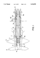
FIG. 1a generally shows a stern tube with a propeller;
FIG. 1 shows a partial longitudinal section through the stern section of a ship with a stern tube, including an outer shaft plus an outer propeller, an inner shaft plus an inner propeller, and corresponding shaft seals and shaft bearings; and
FIGS. 2 and 3 are illustrations, on an enlarged scale, of two different embodiments of the inner shaft seal as illustrated in FIG. 1.
DESCRIPTION OF THE PREFERRED EMBODIMENTS
FIG. 1a generally shows the bottom rear portion of a hull of a ship with a single propeller 1a. Extending rearwardly from the hull is a stern tube 1. The propeller shaft 1b passes from the interior of the ship and to the exterior thereof through the stern tube 1. The propeller 1a can be affixed to the end of the shaft 1b. An alternative embodiment of a stern tube and propeller arrangement is shown in FIG. 1, wherein there are two concentric propeller shafts 2 and 8, along with two propellers 4 and 5. In each of the figures, identical components are identified by the same reference numbers.
In the stern tube 1 for a ship having two concentric propeller shafts, which stern tube is indicated only schematically, there is generally an outer shaft 2 designed as a hollow shaft and mounted in friction bearings 3a. Within a cavity of the outer shaft 2 an inner shaft 8 can be mounted in friction bearings 3b. The outer shaft propeller is designated 4 and the inner shaft propeller is designated 5. The inner shaft seal 6 is generally located between the two propellers 4 and 5, which are at an appropriate distance from one another, while the outer shaft seal 7 is generally located between the outer shaft propeller 4 and the rear end of the stern tube 1.
Though the seal arrangement of the present invention is primarily intended for use in conjunction with the inner shaft seal 6 where problems of clearance fluctuations were previously found, such a seal arrangement could also be used for the outer shaft seal 7, or even for one of the inside seals 20 or 21 disposed within the hull. However it should be understood that seals of essentially similar configurations can be disposed in the alternate locations mentioned above. For purposes of illustration, the seal arrangement of the present invention is described in greater detail below with reference to the inner shaft seal 6, as illustrated in the accompanying FIGS. 2 and 3.
A shaft bushing 9 can preferably be disposed about the inner shaft 8. This shaft bushing 9 can then preferably be torsionally connected in a conventional manner to the inner shaft propeller 5 by means of a flange 9.1. As such, the shaft bushing 9 essentially connects the propeller 5 to the inner shaft 8 for rotation therewith.
A typical seal arrangement for sealing about a propeller shaft can generally provide that the shaft bushing 9 be contacted by at least one sealing gasket. As shown in FIGS. 2 and 3, three gaskets designed as lip seals 10.1, 10.2, 10.3, can be disposed to contact the shaft bushing. In essence, the number of seals required can vary depending on the pressures to which the seals will be subjected, etc. The three lip seals 10.1, 10.2, and 10.3 can be located at intervals, one behind another, such that two lip seals 10.2 and 10.3 essentially correspond to and face the external medium W to be sealed out, while one lip seal 10.1 corresponds to and faces the lubricating oil chamber S. Again, the actual disposition of the lip seals, in regard to their direction of sealing, can be varied depending on the circumstances in which the seals will be used.
The lip seals 10.1, 10.2, 10.3 can preferably be supported by a housing ring 11 which can include four partial housing rings 11.1, 11.2, 11.3, 11.4. The four partial housing rings can preferably be bolted together, one behind another, to form a block in the axial direction. Each lip seal can then be supported between and braced by two partial housing rings.
Some examples of shaft seals for sealing about propeller shafts of ships, including typical lip seals as briefly described above, can be found in the following U.S. patents which have common inventors with the present invention: U.S. Pat. No. 4,395,141 to Gunter Pietsch et al., issued on Jul. 26, 1983 and entitled "Bearing and Seal Assembly for Stern Tubes of Vessels"; U.S. Pat. No. 4,413,829 to Gunter Pietsch, issued on Nov. 11, 1983 and entitled "Shaft Sealing Assembly"; U.S. Pat. No. 4,413,830 to Gunter Pietsch, issued on Nov. 8, 1983 and entitled "Seal Assembly for Rotating Shafts"; U.S. Pat. No. 4,448,425 to Ernst-Peter Von Bergen, issued on May 15, 1984 and entitled "Shaft Seal Assembly with Inflatable Annular Member"; and U.S. Pat. No. 5,137,116 to Ernst-Peter Von Bergen and Gunter Pietsch, issued on Aug. 11, 1992 and entitled "Sealing Device for Rotating Shaft of a Ship Propeller Shaft".
The housing ring 11 can be supported by a supporting ring 12. Such a supporting ring could typically be rigidly mounted by means of a ring flange 12.1 onto the outer shaft 2, which outer shaft 2 is not shown in FIGS. 2 and 3. Between the housing ring 11 and the supporting ring 12, there can generally be an annular gap 22 for allowing fluctuations between the two shafts 2 and 8 during rotation. In order to minimize the fluctuations of this clearance, or annular gap 22, and provide a seal between the housing ring 11 and the supporting 12, the annular gap 22 can preferably be bridged by at least one essentially radial ring wall.
In FIGS. 2 and 3, two such radial ring walls 13, 14 are shown spaced at a distance from one another. The ring walls 13 and 14 can preferably be made from an elastic, fluid-tight material, and can be clamped in a fluid tight manner to both the housing ring 11, on one end, and the supporting ring 12, on the other end. Some of the types of elastic materials which could be used to form the ring walls 13 and 14 could possibly range from an elastomer material to an elastic, or flexible metal sheet, while it is believed that an elastomeric material should preferably be the material of choice. The ring walls can preferably be clamped between two partial housing rings 11.1, 11.2 or can be clamped by clamping rings 15, 19.1, or 19.2, to clamp the ring walls 13 and 14 to either the housing ring 11 or the supporting ring 12.
To further increase the compensation achieved by the invention in the event of excessive fluctuations of the clearance between the outer shaft 2 and the inner shaft 8, in the embodiments illustrated, there can preferably be a friction bearing 16 for the housing ring 11. Such friction bearings are generally well known for rotating shafts, and generally have a surface in contact with the rotating shaft. The bearing shell of such a friction bearing can preferably be supported by a segment 11.1 of the forward-most partial housing ring 11. As such, the segment 11.1 can preferably be extended forwardly along the shaft, and axially towards the shaft 8. The friction bearing can then be disposed on this forwardly and axially extending segment to contact the shaft bushing 9 so that the bearing shell interacts with the forward area of the shaft bushing 9.
In order to keep the friction bearings 16, 3a, 3b, etc. lubricated, the friction bearings can preferably be supplied with a lubricant, such as lubricating oil, or any other appropriate lubricant, by means of passages disposed within the inner shaft 8 and the outer shaft 2. To provide an infeed for the lubricating oil, a longitudinally oriented bore 17 can be provided within the inner shaft 8. This longitudinal passage 17 can empty via branch passages, such as passages 17.1, into the vicinity of the friction bearings. As shown, passages 17.1 empty at the inner surface of the bearing 16. In the above-mentioned extended portion of segment 11.1, there can be a return passage 18 for the lubricating oil exiting from the friction bearing 16. This return passage 18, along with the space between the inner shaft 8 and the outer shaft 2, can provide lubricating oil to the space between the outer shaft 2 and the stern tube 1 via at least one orifice 24 in the wall of the inner shaft 8 (see FIG. 1). The oil can then flow out of the outer space between the outer shaft 2 and the stern tube 1 via outlet 25 to return the lubricating oil back to a circulating pump (not shown). One type of lubricating system for a sealing arrangement of a propeller shaft is disclosed in the above mentioned U.S. Pat. No. 5,137,116.
For the above-mentioned compensation for clearance fluctuations, essentially only the displacement of the housing ring 11 in the radial direction is desired. As discussed, this is essentially made possible as a result of the elastic ring walls 13, 14. However, without additional guides, displacement in the axial direction may also occur. In order to preferably avoid such axial displacement, at least one corresponding guide, extending in the radial direction, can be provided for the housing ring 11. Such a guide, as illustrated in FIG. 2, can essentially be formed by a groove, or channel, which can be formed by the supporting ring 12 and its clamping rings 19.1, 19.2, and a corresponding projection, formed by the partial housing rings 11.1, 11.2, which projection essentially projects into the channel while maintaining a slight lateral clearance from the base of the channel. As illustrated in FIG. 2, the projection-channel guide arrangement provides a pair of adjoining axial guide surfaces illustrated at 26 and 27.
As illustrated in FIG. 3, such a guide could also be formed by a projection 9.2 of the shaft bushing 9, which projection can preferably be disposed in the vicinity of the friction bearing 16, and a corresponding groove or channel located in the extended area of the partial housing ring 11.1. In this embodiment of FIG. 3, the projection-channel guide arrangement provides a pair of adjoining axial guide surfaces illustrated at 28 and 29. With such an arrangement, the projection 9.2 can still be configured to contain branch lubricant carrying passages and thus can also act as a means for the transmission of the lubricant to the friction bearing 16. Alternatively, an additional possible guide arrangement of FIG. 3 could be considered to be formed by a projection 11.1' extending from the housing 11.1 into a recess 9' of the shaft bushing 9.
One feature of the invention resides broadly in the seal arrangement of propeller drives for ships with two concentric propeller shafts rotating in opposite directions from one another, and with a seal for the outer shaft and a seal for the inner shaft, whereby the seals, designed as lip seals, are connected to the stern tube of the outer shaft in a water-tight manner, characterized by the fact that the inner shaft seal 6 is supported by a housing ring 11, which is connected in a fluid-tight manner to a supporting ring 12 which is concentric with it but which is at a radial distance from it by means of elastic ring walls 13, 14 which prevent fluid penetration, whereby the supporting ring 12 represents the connecting element for the fluid-tight connection to the external shaft 2.
Another feature of the invention resides broadly in the seal arrangement, characterized by the fact that the fluid-tight connection of the ring walls 13, 14 to the housing ring 11 and the supporting ring 12 is made by clamping the edges of the ring walls 13, 14 between clamping rings 11.2, 11.1, 15 and 19.1, 19.2, 12.1.
Yet another feature of the invention resides broadly in the seal arrangement, characterized by the fact that the housing ring 11, in its terminal area 11.1, has an axial extension, which is designed as a support for the bearing shell of a friction bearing 16 which works together with the inner shaft 8 or with a shaft bushing 9 pulled onto the inner shaft 8.
Still another feature of the invention resides broadly in the seal arrangement, characterized by the fact that the housing ring 11 is prevented from moving in the axial direction by a guide.
Still yet another feature of the invention resides broadly in the seal arrangement, characterized by the fact that the guide consists of a ring-shaped hole in the supporting ring 19.1, 19.2, 12.1, into which a corresponding projection of the housing ring 11.2, 11.1, 15 projects.
Another feature of the invention resides broadly in the seal arrangement, characterized by the fact that the guide consists of a ring-shaped hole in the housing ring 11.1 in the vicinity of the friction bearing 16, into which a corresponding projection 9.1 of a shaft bushing 9 projects.
Still another feature of the invention resides broadly in the seal arrangement, characterized by the fact that when pressure circulating lubrication is used for the friction bearing 16, the oil feed to the friction bearing 16 takes place through a lubrication passage 17 inside the inner shaft 8, whereby there is a return passage 18 in the housing ring 11.1 for the return flow of the oil.
Yet still another feature of the invention resides broadly in the seal arrangement, characterized by the use of a multiple lip seal with two or more lip seals 10.1, 10.2, 10.3 located behind one another and at some distance from one another in the axial direction, whereby the housing ring 11 forms a block of partial housing rings 11.1, 11.2, 11.3-11.4, and whereby one of the lip seals is braced between each two partial housing rings.
All, or substantially all, of the components and methods of the various embodiments may be used with at least one embodiment or all of the embodiments, if any, described herein.
All of the patents, patent applications and publications recited herein, if any, are hereby incorporated by reference as if set forth in their entirety herein.
The details in the patents, patent applications and publications may be considered to be incorporable, at applicant's option, into the claims during prosecution as further limitations in the claims to patentably distinguish any amended claims from any applied prior art.
The appended drawings, in their entirety, including all dimensions, proportions and/or shapes in at least one embodiment of the invention, are, if applicable, accurate and to scale and are hereby incorporated by reference into this specification.
The invention as described hereinabove in the context of the preferred embodiments is not to be taken as limited to all of the provided details thereof, since modifications and variations thereof may be made without departing from the spirit and scope of the invention.

Claims (6)

What is claimed is:
1. A seal arrangement for providing seals about a propeller shaft arrangement of a ship, the shaft arrangement including inner and outer propeller shafts disposed concentrically to one another and passing through the hull, said seal arrangement comprising:
first seal means for sealing between the outer propeller shaft and the hull, said first seal means being disposed to provide a fluid-tight seal between the outer propeller shaft and the hull; and
second seal means for being disposed between the inner and outer propeller shafts, said second seal means being disposed to provide a fluid tight seal between the inner and outer propeller shafts, said second seal means comprising:
a housing for being disposed about the inner shaft, said housing having an inner portion disposed towards the inner shaft, and an outer portion disposed away from the inner shaft;
support means for maintaining a position of said housing about the inner shaft, said support means for being mounted to the outer propeller shaft, said support means being disposed about said housing and spaced radially from said outer portion of said housing to define at least a first clearance between said support means and said housing;
at least two sealing elements for being disposed between the inner shaft and said housing, said at least two sealing elements being first and second sealing elements, each of said first and second sealing elements having a portion for being disposed in sealing engagement with the inner shaft;
two flexible members disposed between said housing and said support means to seal said at least a first clearance between said housing and said support means, each of said two flexible members being configured for allowing radial movements between the inner shaft and the outer shaft;
said two flexible members being a first flexible member and a second flexible member;
each of said first and second flexible members sealing between said housing and said support means comprising an element separate and distinct from said first and second sealing elements sealing between said housing and the inner shaft;
each of said first and second flexible members extending between said support means and said housing;
each of said first and second sealing elements extending between said housing and the inner shaft;
each of said first and second flexible members being disposed at a substantial distance from said first and second sealing element;
said housing comprising a tubular member for being disposed about the inner propeller shaft, said housing having an exterior surface disposed towards said support means, an interior surface for being disposed towards the inner shaft, a first axial end for being disposed towards the hull of the ship, and a second axial end disposed opposite said first end;
each of said first and second flexible members comprising an outer peripheral edge connected to said support means, and an inner edge connected to said housing;
each of said first and second sealing elements comprising an outer peripheral edge connected to said housing and an inner edge for being disposed about the inner shaft, said inner edge of each of said first and second sealing elements comprising said sealing portion;
said housing comprising means for separately clamping each of: said outer peripheral edges of said first and second sealing elements, and said inner edges of said first and second flexible members, to said housing;
said means for separately clamping comprising:
a first annular recess and a second annular recess both being disposed about said exterior surface of said housing;
said first annular recess being disposed for receiving said inner edge of said first flexible member therewithin;
said second annular recess being disposed for receiving said inner edge of said second flexible member therewithin;
a third annular recess being disposed about said interior surface of said housing for receiving said outer peripheral edge of said first sealing element therewithin; and
first ring means being disposed adjacent each of said first, second, and third annular recesses to clamp said inner edge of each of said first and second flexible members to said housing and clamp said outer edges of said first and second sealing elements to said housing;
said support means comprising a tubular member disposed concentrically about said housing, said support means having an interior surface disposed towards said housing;
said support means comprising a first annular recess and a second annular recess both being disposed about said interior surface thereof;
said first annular recess of said support means being disposed for receiving said outer peripheral edge of said first flexible member therein;
said second annular recess of said support means being disposed for receiving said outer peripheral edge of said second flexible member therein;
said support means comprising second ring means disposed about said support means and adjacent said first annular recess and said second annular recess of said support means to clamp said outer peripheral edge of each of said first and second flexible members to said support means;
said first flexible member being disposed adjacent said first axial end of said housing, and said second flexible member being disposed adjacent said second axial end of said housing;
each of said first and second flexible members comprising a flexible ring-shaped member having an inner edge disposed towards said housing and an outer peripheral disposed towards said support means;
each said inner edge of said first and second flexible members being fixedly attached by said first ring means to said housing in a corresponding one of said first and second annular recesses of said housing, and each said outer peripheral edge of said first and second flexible members being fixedly attached by said second ring means to said support means in a corresponding one of said first and second annular recesses of said support means;
said first sealing element being disposed adjacent said second axial end of said housing;
said first ring means comprising a first ring being disposed axially adjacent said second axial end of said housing for axially clamping both said second flexible member and said first sealing element to said second axial end of said housing;
said first ring having a first side disposed towards said support means and a second side disposed axially opposite said first side;
said second side comprising an annular recess for receiving said second sealing element therein; and
said first ring means additionally comprising a second ring being disposed axially adjacent said first ring for axially clamping said second sealing element in said annular recess of said second side of said first ring.
2. The seal arrangement according to claim 1, wherein:
said first and second sealing elements comprise first and second lip seals, respectively;
each of said lip seals having a substantially radially extending portion comprising said outer peripheral edge of said lip seals, and an axially extending portion comprising said inner edge of said lip seals;
said axially extending portion of said first lip seal for being disposed forwardly along the inner shaft towards said first axial end of said housing to seal in lubricating oil;
said axially extending portion of said second lip seal for being disposed aftwardly along the inner shaft away from said first ring to seal out seawater;
said housing further comprises a friction bearing disposed adjacent said first axial end of said housing for being disposed in contact with the inner propeller shaft, said friction bearing being configured for eliminating radial play between said housing and the inner propeller shaft; and
the inner shaft comprises passage means for providing lubricating oil to said friction bearing.
3. The seal arrangement according to claim 2, wherein:
said seal arrangement further comprises a bearing bush for being disposed about the inner propeller shaft within said housing;
said housing comprises, adjacent said first axial end, a portion extending radially inwardly twoards said bearing bush;
said radially extending portion of said housing comprising a first surface being disposed adjacent said bearing bush;
said first surface of said radially extending portion comprising said friction bearing, said friction bearing being disposed in contact with said bearing bush;
said radially extending portion comprises an annular extension;
said seal arrangement further comprises a plurality of passages for circulation of lubricating oil through said seal arrangement;
said bearing bush comprising at least one axial passage for being disposed in alignment with he passage means of the inner propeller shaft to provide lubricant from a lubricant supply source to lubricate said friction bearing, the lubricant for flowing axially along said bearing bush in both a forward direction of the inner shaft and a rearward direction of the inner shaft; and
said radially extending portion of said housing has at least one lubricant passage therethrough for returning the lubricant portion which flows in the rearward direction back in a forward direction to return the rearward flowing lubricant back to the lubricant supply source.
4. A propeller shaft arrangement of a ship, said propeller shaft arrangement comprising:
an inner propeller shaft and an outer propeller shaft disposed concentrically with respect to one another and for passing through the hull of a ship;
a seal arrangement for providing seals about said propeller shaft arranqement, said seal arrangement comprising:
first seal means for sealing between said outer propeller shaft and the hull, said first seal means being disposed to provide a fluid-tight seal between said outer propeller shaft and the hull; and
second seal means disposed between said inner and outer propeller shafts, said second seal means being disposed to provide a fluid tight seal between said inner and outer propeller shafts, said second seal means comprising:
a housing disposed about said inner shaft, said housing having an inner portion disposed towards said inner shaft, and an outer portion disposed away from said inner shaft;
support means for maintaining a position of said housing about said inner shaft, said support means being mounted to said outer propeller shaft, said support means being disposed about said housing and spaced radially from said outer portion of said housing to define at least a first clearance between said support means and said housing;
at least two sealing elements being disposed between said inner shaft and said housing, said at least two sealing elements being a first sealing element and a second sealing element, each of said first and second sealing elements having a portion being disposed in sealing engagement with said inner shaft;
two flexible members disposed between said housing and said support means to seal said at least a first clearance between said housing and said support means, each of said two flexible members being configured for allowing radial movements between said inner shaft and said outer shaft;
said two flexible members being a first flexible member and a second flexible member;
each of said first and second flexible members sealing between said housing and said support means comprising an element separate and distinct from said first and second sealing elements sealing between said housing and said inner shaft;
each of said first and second flexible members extending between said support means and said housing;
each of said first and second sealing elements extending between said housing and said inner shaft;
each of said first and second flexible members being disposed at a substantial distance from said first and second sealing elements;
said housing comprising a tubular member being disposed about said inner propeller shaft, said housing having an exterior surface disposed towards said support means, an interior surface disposed towards said inner shaft, a first axial end for being disposed towards the hull of the ship, and a second axial end disposed opposite said first end;
each of said first and second flexible members comprising an outer peripheral edge connected to said support means, and an inner edge connected to said housing;
each of said first and second sealing elements comprising an outer peripheral edge connected to said housing, and an inner edge being disposed about said inner shaft, said inner edge of each of said first and second sealing elements comprising said sealing portion;
said housing comprising means for separately clamping each of: said outer peripheral edges of said first and second sealing elements, and said inner edges of said first and second flexible members, to said housing;
said means for separately clamping comprising:
a first annular recess and a second annular recess both being disposed about said exterior surface of said housing;
said first annular recess being disposed for receiving said inner edge of said first flexible member therewithin;
said second annular recess being disposed for receiving said inner edge of said second flexible member therewithin;
a third annular recess being disposed about said interior surface of said housing for receiving said outer peripheral edge of said first sealing element therewithin; and
first ring means being disposed adjacent each of said first, second, and third annular recesses to clamp said inner edge of each of said first and second flexible members to said housing and clamp said outer edges of said first and second sealing elements to said housing;
said support means comprising a tubular member disposed concentrically about said housing, said support means having an interior surface disposed towards said housing;
said support means comprising a first annular recess and a second annular recess both being disposed about said interior surface thereof;
said first annular recess of said support means being disposed for receiving said outer peripheral edge of said first flexible member therein;
said second annular recess of said support means being disposed for receiving said outer peripheral edge of said second flexible member therein;
said support means comprising second ring means disposed about said support means and adjacent said first annular recess and said second annular recess of said support means to clamp said outer peripheral edge of each of said first and second flexible members to said support means;
said first flexible member being disposed adjacent said first axial end of said housing, and said second flexible member being disposed adjacent said second axial end of said housing;
each of said first and second flexible members comprising a flexible ring-shaped member having an inner edge disposed towards said housing and an outer peripheral edge disposed towards said support means;
each said inner edge of said first and second flexible members being fixedly attached by said first means to said housing in a corresponding one of said first and second annular recesses of said housing, and each said outer peripheral edge of said first and second flexible members being fixedly attached by said second ring means to said support means in a corresponding one of said first and second annular recesses of said support means;
said first sealing element being disposed adjacent said second axial end of said housing; and
said first ring means comprising a first ring being disposed axially adjacent said second axial end of said housing for axially clamping both said second flexible member and said first sealing element to said second axial end of said housing;
said first ring having a first side disposed towards said support means and a second side disposed axially opposite said first side;
said second side comprising an annular recess for receiving said second sealing element therein; and
said first ring means additionally comprising a second ring being disposed axially adjacent said first ring for axially clamping said second sealing element in said annular recess of said second side of said first ring.
5. The propeller shaft arrangement according to claim 4, wherein:
said first and second sealing elements comprise first and second lip seals, respectively;
each of said lip seals having a substantially radially extending portion comprising said outer peripheral edge of said lip seals, and an axially extending portion comprising said inner edge of said lip seals;
said axially extending portion of said first lip seal being disposed forwardly along said inner shaft towards said first axial end of said housing to seal in lubricating oil;
said axially extending portion of said second lip seal being disposed aftwardly along said inner shaft away from said first ring to seal out seawater;
said housing further comprises a friction bearing dispose adjacent said first axial end of said housing and being disposed in contact with said inner propeller shaft, said friction bearing being configured for eliminating radial play between said housing and said inner propeller shaft; and
said inner shaft comprises passage means for providing lubricating oil to said friction bearing.
6. The propeller shaft arrangement according to claim 5, wherein:
said seal arrangement further comprises a bearing bush being disposed about said inner propeller shaft within said housing;
said housing comprises, adjacent said first axial end, a portion extending radially inwardly towards said bearing bush;
said radially extending portion of said housing comprising a first surface being disposed adjacent said bearing bush;
said first surface of said radially extending portion comprising said friction bearing, said friction bearing being disposed in contact with said bearing bush;
said radially extending portion comprises an annular extension;
said seal arrangement further comprises a plurality of passages for circulation of lubricating oil through said seal arrangement;
said bearing bush comprising at least one axial passage being disposed in alignment with said passage means of said inner propeller shaft to provide lubricant from a lubricant supply source to lubricate said friction bearing, the lubricant for flowing axially along said bearing bush in both a forward direction of said inner shaft and a rearward direction of said inner shaft; and
said radially extending portion of said housing has at least one lubricant passage therethrough for returning the lubricant portion which flows in the rearward direction back in a forward direction to return the rearward flowing lubricant back to the lubricant supply source.
US08/560,006 1992-07-09 1995-11-17 Seal arrangement for propeller shafts of ships Expired - Lifetime US5624290A (en)

Priority Applications (1)

Application Number Priority Date Filing Date Title
US08/560,006 US5624290A (en) 1992-07-09 1995-11-17 Seal arrangement for propeller shafts of ships

Applications Claiming Priority (5)

Application Number Priority Date Filing Date Title
DE4222564A DE4222564C2 (en) 1992-07-09 1992-07-09 Sealing arrangement of propeller drives for ships with two concentric counter-rotating propeller shafts
DE4222564 1992-07-09
US08/088,872 US5356320A (en) 1992-07-09 1993-07-08 Seal arrangement for propeller shafts of ships
US08/313,755 US5492492A (en) 1992-07-09 1994-09-28 Seal arrangement for propeller shafts of ships
US08/560,006 US5624290A (en) 1992-07-09 1995-11-17 Seal arrangement for propeller shafts of ships

Related Parent Applications (1)

Application Number Title Priority Date Filing Date
US08/313,755 Division US5492492A (en) 1992-07-09 1994-09-28 Seal arrangement for propeller shafts of ships

Publications (1)

Publication Number Publication Date
US5624290A true US5624290A (en) 1997-04-29

Family

ID=6462844

Family Applications (3)

Application Number Title Priority Date Filing Date
US08/088,872 Expired - Lifetime US5356320A (en) 1992-07-09 1993-07-08 Seal arrangement for propeller shafts of ships
US08/313,755 Expired - Lifetime US5492492A (en) 1992-07-09 1994-09-28 Seal arrangement for propeller shafts of ships
US08/560,006 Expired - Lifetime US5624290A (en) 1992-07-09 1995-11-17 Seal arrangement for propeller shafts of ships

Family Applications Before (2)

Application Number Title Priority Date Filing Date
US08/088,872 Expired - Lifetime US5356320A (en) 1992-07-09 1993-07-08 Seal arrangement for propeller shafts of ships
US08/313,755 Expired - Lifetime US5492492A (en) 1992-07-09 1994-09-28 Seal arrangement for propeller shafts of ships

Country Status (9)

Country Link
US (3) US5356320A (en)
JP (1) JP3386855B2 (en)
KR (1) KR970010828B1 (en)
CN (1) CN1037594C (en)
DE (1) DE4222564C2 (en)
GB (1) GB2268460B (en)
NL (1) NL192827C (en)
RU (1) RU2062733C1 (en)
SE (1) SE510406C2 (en)

Cited By (12)

* Cited by examiner, † Cited by third party
Publication number Priority date Publication date Assignee Title
GB2365936A (en) * 2000-08-17 2002-02-27 B & V Industrietechnik Gmbh An apparatus for the sealing of drive shafts
US20050253340A1 (en) * 2000-04-13 2005-11-17 Ashbridge & Roseburgh Inc. Sealing apparatus having sequentially engageable seals
US20060108745A1 (en) * 2004-11-22 2006-05-25 Mide Technology Corporation Fluid-activated shaft seal
US20060186604A1 (en) * 2005-02-24 2006-08-24 Freudenberg-Nok General Partnership Dynamic seal
US20060186603A1 (en) * 2005-02-24 2006-08-24 Freudenberg-Nok General Partnership Dynamic seal
US20080303218A1 (en) * 2004-11-22 2008-12-11 Mide Technology Corporation Fluid-activated shaft seal
US20100301566A1 (en) * 2004-11-22 2010-12-02 Van Schoor Marthinus Fluid activated shaft seal
US20110248450A1 (en) * 2010-04-13 2011-10-13 Van Schoor Marthinus Bulkhead seal
CN105003649A (en) * 2015-07-23 2015-10-28 成都广迈科技有限公司 Connecting-device seal cartridge
US9695937B2 (en) 2014-02-04 2017-07-04 Freudenberg-Nok General Partnership Energy saving seal with vacuum induced counter-balance and rocking feature
US9714710B2 (en) 2014-02-04 2017-07-25 Freudenberg-Nok General Partnership Energy saving self-contact seal with pushing bead
US9759330B2 (en) 2014-02-04 2017-09-12 Freudenberg-Nok General Partnership Energy saving seal with rocking dust lip

Families Citing this family (17)

* Cited by examiner, † Cited by third party
Publication number Priority date Publication date Assignee Title
DE4222564C2 (en) * 1992-07-09 2001-12-13 Blohm & Voss Ind Gmbh Sealing arrangement of propeller drives for ships with two concentric counter-rotating propeller shafts
JPH09102591A (en) * 1995-07-28 1997-04-15 Toshiba Corp Semiconductor device and manufacture thereof
JP2015516921A (en) 2012-05-04 2015-06-18 サムスン ヘビー インダストリーズ カンパニー リミテッド Ship propulsion device
KR101422485B1 (en) * 2012-05-09 2014-07-23 삼성중공업 주식회사 Propulsion apparatus for ship and ship having the propulsion apparatus
KR101422481B1 (en) * 2012-05-09 2014-07-28 삼성중공업 주식회사 Propulsion apparatus for ship and ship having the same
KR101399846B1 (en) * 2012-05-09 2014-05-28 삼성중공업 주식회사 Propulsion apparatus for ship and ship having the same
KR101422488B1 (en) * 2012-05-09 2014-07-29 삼성중공업 주식회사 Propulsion apparatus for ship and ship having the propulsion apparatus
DE102012016447B4 (en) * 2012-08-18 2022-12-01 Skf Marine Gmbh Sealing for rotating shafts of ship propeller shafts
CA2932197C (en) * 2013-10-22 2021-08-10 Skf Blohm + Voss Industries Gmbh Sealing system and sealing ring
EP3015358B1 (en) * 2014-11-03 2019-01-02 ABB Oy Seal arrangement for a propeller shaft
DE102015003048B4 (en) 2015-01-26 2021-10-28 Sew-Eurodrive Gmbh & Co Kg Sealing arrangement for gears and gears with such a sealing arrangement
CN108290627B (en) * 2015-12-02 2021-04-27 沃尔沃遍达公司 Propeller drive assembly
EP3239546B1 (en) * 2016-04-25 2018-11-14 GE Energy Power Conversion Technology Ltd Propulsion unit for watercraft including a movable housing and a hydraulic fluid conditioning module
CN109372991A (en) * 2018-11-28 2019-02-22 东台市海鹏船舶配件有限公司 A kind of radial extrusion type marine screw shaft sealing device
CN111120658B (en) * 2020-01-03 2022-04-05 湖南永盛船舶有限公司 Marine stern shaft sealing device with adjustable
CN111661298B (en) * 2020-04-24 2021-11-26 武汉船用机械有限责任公司 Propeller shaft protection device and installation method thereof
CN112302724A (en) * 2020-10-15 2021-02-02 武汉第二船舶设计研究所(中国船舶重工集团公司第七一九研究所) Steam turbine and marine steam power propulsion device

Citations (5)

* Cited by examiner, † Cited by third party
Publication number Priority date Publication date Assignee Title
US3413008A (en) * 1965-01-26 1968-11-26 Sealol Shaft seal
DE1901620A1 (en) * 1968-02-06 1969-08-28 Algoship Internat Ltd Propeller drive for ships with concentrically arranged, counter-rotating propeller shafts
US3565447A (en) * 1967-10-05 1971-02-23 Inst Schiffbau Stern tube seal
US3625523A (en) * 1970-02-13 1971-12-07 Waukesha Bearings Corp Aft sealing assembly for stern tubes
JPS62279194A (en) * 1986-05-28 1987-12-04 Eagle Ind Co Ltd Oil supplying method for stern pipe bearing

Family Cites Families (6)

* Cited by examiner, † Cited by third party
Publication number Priority date Publication date Assignee Title
DD65753A (en) *
US3169504A (en) * 1963-12-16 1965-02-16 Wankesha Bearings Corp Cathodic system
DE2925244C2 (en) * 1979-06-22 1982-09-30 Howaldtswerke-Deutsche Werft Ag Hamburg Und Kiel, 2300 Kiel Sealing arrangement for stern tube systems
JPH0535249Y2 (en) * 1988-03-31 1993-09-07
DE3815655C2 (en) * 1988-05-07 1994-04-14 Blohm Voss Ag Sealing for rotating shafts, especially stern tube sealing
DE4222564C2 (en) * 1992-07-09 2001-12-13 Blohm & Voss Ind Gmbh Sealing arrangement of propeller drives for ships with two concentric counter-rotating propeller shafts

Patent Citations (5)

* Cited by examiner, † Cited by third party
Publication number Priority date Publication date Assignee Title
US3413008A (en) * 1965-01-26 1968-11-26 Sealol Shaft seal
US3565447A (en) * 1967-10-05 1971-02-23 Inst Schiffbau Stern tube seal
DE1901620A1 (en) * 1968-02-06 1969-08-28 Algoship Internat Ltd Propeller drive for ships with concentrically arranged, counter-rotating propeller shafts
US3625523A (en) * 1970-02-13 1971-12-07 Waukesha Bearings Corp Aft sealing assembly for stern tubes
JPS62279194A (en) * 1986-05-28 1987-12-04 Eagle Ind Co Ltd Oil supplying method for stern pipe bearing

Cited By (29)

* Cited by examiner, † Cited by third party
Publication number Priority date Publication date Assignee Title
US20050253340A1 (en) * 2000-04-13 2005-11-17 Ashbridge & Roseburgh Inc. Sealing apparatus having sequentially engageable seals
US7354046B2 (en) * 2000-04-13 2008-04-08 Ashbridge & Roseburgh Inc. Sealing apparatus having sequentially engageable seals
CN1299032C (en) * 2000-08-17 2007-02-07 B+V工业技术股份有限公司 Sealed device for drive-shaft
GB2365936B (en) * 2000-08-17 2002-10-02 B & V Industrietechnik Gmbh Apparatus for the sealing of a drive shaft for a propeller of a ship
GB2365936A (en) * 2000-08-17 2002-02-27 B & V Industrietechnik Gmbh An apparatus for the sealing of drive shafts
US20100301566A1 (en) * 2004-11-22 2010-12-02 Van Schoor Marthinus Fluid activated shaft seal
US7828299B2 (en) 2004-11-22 2010-11-09 Mide Technology Corporation Fluid-activated shaft seal
US8419020B2 (en) 2004-11-22 2013-04-16 Mide Technology Corporation Fluid activated shaft seal
AU2005327082B2 (en) * 2004-11-22 2011-07-14 Mide Technology Corporation Fluid-activated shaft seal
US20080303218A1 (en) * 2004-11-22 2008-12-11 Mide Technology Corporation Fluid-activated shaft seal
US7686308B2 (en) * 2004-11-22 2010-03-30 Mide Technology Corporation Fluid-activated shaft seal
US20060108745A1 (en) * 2004-11-22 2006-05-25 Mide Technology Corporation Fluid-activated shaft seal
US7854432B2 (en) 2005-02-24 2010-12-21 Freudenberg-Nok General Partnership Dynamic seal
US20060186604A1 (en) * 2005-02-24 2006-08-24 Freudenberg-Nok General Partnership Dynamic seal
US7770897B2 (en) 2005-02-24 2010-08-10 Freudenberg-Nok General Partnership Dynamic seal
US7854433B2 (en) 2005-02-24 2010-12-21 Freudenberg-Nok General Partnership Dynamic seal
US20060186603A1 (en) * 2005-02-24 2006-08-24 Freudenberg-Nok General Partnership Dynamic seal
US20110024990A1 (en) * 2005-02-24 2011-02-03 Freudenberg-Nok General Partnership Dynamic Seal
US20110024989A1 (en) * 2005-02-24 2011-02-03 Freudenberg-Nok General Partnership Dynamic Seal
US20080157481A1 (en) * 2005-02-24 2008-07-03 Freudenberg-Nok General Partnership Dynamic Seal
US8011673B2 (en) 2005-02-24 2011-09-06 Freudenberg-Nok General Partnership Dynamic seal
US20100264604A1 (en) * 2005-02-24 2010-10-21 Freudenberg-Nok General Partnership Dynamic Seal
US8066287B2 (en) 2005-02-24 2011-11-29 Freudenberg-Nok General Partnership Dynamic seal
US20110248450A1 (en) * 2010-04-13 2011-10-13 Van Schoor Marthinus Bulkhead seal
US8608172B2 (en) * 2010-04-13 2013-12-17 Mide Technology Corporation Bulkhead seal
US9695937B2 (en) 2014-02-04 2017-07-04 Freudenberg-Nok General Partnership Energy saving seal with vacuum induced counter-balance and rocking feature
US9714710B2 (en) 2014-02-04 2017-07-25 Freudenberg-Nok General Partnership Energy saving self-contact seal with pushing bead
US9759330B2 (en) 2014-02-04 2017-09-12 Freudenberg-Nok General Partnership Energy saving seal with rocking dust lip
CN105003649A (en) * 2015-07-23 2015-10-28 成都广迈科技有限公司 Connecting-device seal cartridge

Also Published As

Publication number Publication date
SE9302361D0 (en) 1993-07-07
RU2062733C1 (en) 1996-06-27
JP3386855B2 (en) 2003-03-17
NL9301206A (en) 1994-02-01
US5492492A (en) 1996-02-20
GB2268460B (en) 1996-03-06
CN1087592A (en) 1994-06-08
KR940005463A (en) 1994-03-21
GB9314020D0 (en) 1993-08-18
JPH0687490A (en) 1994-03-29
DE4222564C2 (en) 2001-12-13
GB2268460A (en) 1994-01-12
SE510406C2 (en) 1999-05-17
CN1037594C (en) 1998-03-04
NL192827C (en) 1998-03-04
KR970010828B1 (en) 1997-07-01
SE9302361L (en) 1994-01-10
US5356320A (en) 1994-10-18
DE4222564A1 (en) 1994-01-13
NL192827B (en) 1997-11-03

Similar Documents

Publication Publication Date Title
US5624290A (en) Seal arrangement for propeller shafts of ships
US5374208A (en) Ship, in particular deep draft vessel having concentric, contra-rotating propellers
EP0037210B1 (en) High pressure upstream pumping seal combination
US4413829A (en) Shaft sealing assembly
US3934952A (en) Leakproof seal for bearings
US4448425A (en) Shaft seal assembly with inflatable annular member
US4085941A (en) Stern seals for ships
US5366398A (en) Marine dual propeller lower bore drive assembly
JP2872866B2 (en) Bearing device for marine contra-rotating propeller shaft
KR102300096B1 (en) Shaft sealing device of double reversing propeller unit for marine use
JPH0210000B2 (en)
US4344630A (en) Sealingly mounting arrangement for propeller shafts of watercraft
US5419724A (en) Stern tube bearing system for contra-rotating propeller shafts of a water-borne ship
US5462463A (en) Marine dual propeller lower bore drive assembly
JP2909948B2 (en) Stern tube shaft sealing device
WO1993018965A1 (en) Through hull assemblies for marine drives
JP3693698B2 (en) Device for sealing the end of a propeller shaft tube of a ship
JPH08156888A (en) Shaft sealing device for ship propeller shaft
JP2005041348A (en) Shaft seal device and shaft seal method for propeller shaft for ship
JPH07242198A (en) Stern tube sealing device
US4643642A (en) Multi-bladed propeller and shaft assembly
EP0175533B1 (en) Multi-bladed propeller and shaft assembly
JPH0310993A (en) Seal lubricating construction for propeller shaft for marine twin contra-propeller
JPH0478785A (en) Middle bearing structure of marine contra-rotating propeller shaft
JPS62210198A (en) Bearing lubricating device for marine counter-rotating propeller

Legal Events

Date Code Title Description
AS Assignment

Owner name: BLOHM + VOSS HOLDING AG, GERMANY

Free format text: CHANGE OF NAME;ASSIGNOR:BLOHM + VOSS AG;REEL/FRAME:008251/0638

Effective date: 19960308

STCF Information on status: patent grant

Free format text: PATENTED CASE

AS Assignment

Owner name: BLOHM + VOSS INDUSTRIE GMBH, GERMANY

Free format text: ASSIGNMENT OF ASSIGNORS INTEREST;ASSIGNOR:BLOHM + VOSS HOLDING AG;REEL/FRAME:008559/0542

Effective date: 19970512

CC Certificate of correction
FEPP Fee payment procedure

Free format text: PAYOR NUMBER ASSIGNED (ORIGINAL EVENT CODE: ASPN); ENTITY STATUS OF PATENT OWNER: LARGE ENTITY

FPAY Fee payment

Year of fee payment: 4

FPAY Fee payment

Year of fee payment: 8

FPAY Fee payment

Year of fee payment: 12