US5623874A - Counter-pressure means for effectuating perforations and/or punchings at offset sheet printing machines - Google Patents
Counter-pressure means for effectuating perforations and/or punchings at offset sheet printing machines Download PDFInfo
- Publication number
- US5623874A US5623874A US08/540,662 US54066295A US5623874A US 5623874 A US5623874 A US 5623874A US 54066295 A US54066295 A US 54066295A US 5623874 A US5623874 A US 5623874A
- Authority
- US
- United States
- Prior art keywords
- cylinder
- foil
- printing
- blanket
- rubber blanket
- Prior art date
- Legal status (The legal status is an assumption and is not a legal conclusion. Google has not performed a legal analysis and makes no representation as to the accuracy of the status listed.)
- Expired - Fee Related
Links
Images

Classifications
-
- B—PERFORMING OPERATIONS; TRANSPORTING
- B41—PRINTING; LINING MACHINES; TYPEWRITERS; STAMPS
- B41G—APPARATUS FOR BRONZE PRINTING, LINE PRINTING, OR FOR BORDERING OR EDGING SHEETS OR LIKE ARTICLES; AUXILIARY FOR PERFORATING IN CONJUNCTION WITH PRINTING
- B41G7/00—Auxiliary perforating apparatus associated with printing devices
Definitions
- the present invention relates to a counter-pressure means for effectuating perforations and/or punchings at offset sheet printing machines.
- Offset printing machines comprise an impression cylinder--also called counter-impression cylinder--and a cooperating rubber blanket cylinder.
- the rubber blanket cylinder is provided with a rubber blanket and is pressed against the impression cylinder with a definite pressure.
- For effectuating perforations it is known to mount a perforating ribbon on the impression cylinder whereas the rubber blanket is left unchanged on the blanket cylinder.
- the rubber blanket presents the disadvantage during perforation that it does not allow an optimal perforating due to its softness, and that it limits the operational speed of the entire printing group and of optionally connected further printing groups.
- the sheets are deformed by the rubber blanket during perforating in such a manner that no correct sheet stack can be built up afterwards. The same effect arises during effectuating punchings, because the rubber blanket is to flexible.
- U.S. Pat. No. 4,178,402 discloses a multi-ply cylinder blanket for offset printing machines enabling, according to this patent, high quality printing.
- those blankets are not suitable for perforations or punchings since the surface of the blankets is made of rubber, besides the fact that for effectuating perforations the complicated construction of the multi-ply blanket is far too cost intensive.
- U.S. Pat. No. 4,854,237 further discloses a holding arrangement to use for printing machine cylinder underlays with a magnetic foil strip.
- the first object is attained in that the means comprises a foil provided with strips at two opposing of its edges, the foil and strips being executed for being fastened within fixing means of either a rubber blanket cylinder of a printing group of the printing machine or of a forme cylinder of an auxiliary coating module of the printing machine.
- the foil comprises an underlying blanket at its underside or its upper side in order to achieve a total thickness which corresponds to the thickness of the known, usual rubber blanket.
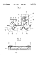
- FIG. 1 schematically shows the arrangement of a printing group and a coating module of an offset sheet printing machine
- FIG. 2 shows a sectional view of the metal foil of this invention, provided with strips, and
- FIG. 3 shows a detail of FIG. 1 at an enlarged scale.
- FIG. 1 shows in a schematical manner one printing group of optionally several printing groups of an offset sheet printing machine, comprising a plate cylinder 1, an impression cylinder 2, and a rubber blanket cylinder arranged between these two cylinders.
- a foil 4 instead of a rubber blanket.
- an usual rubber blanket is mounted on the rubber blanket cylinder 3.
- a perforating ribbon 5 is mounted on the impression cylinder 2, see FIG. 3, which teeth are showwing in the direction of the rubber blanket cylinder 3 in order to perforate the paper running between these two cylinders.
- suitable means are mounted on impression cylinder 2.
- FIG. 1 further shows an inking system 6 and a dampening system 7. These systems comprise different rollers which transfer printing ink or water on the plate cylinder 1, respectively.
- the paper sheets 8 pass from an intermediate drum 9 to a first feed drum 10, then on the impression cylinder 2 and afterwards to a second feed drum 11. From this drum 11 the sheets are optionally passed to a further drum and, if provided, to another printing group or a coating module 19.
- FIG. 3 shows a cross-sectional view of the plate cylinder 1, the impression cylinder 2 and the rubber blanket cylinder 3 at an enlarged scale.
- the plate cylinder 1 comprising a printing plate 12 mounted thereon is well known, being differently constructed dependent on the various machine types.
- the perforating ribbon 5 is mounted on the impression cylinder 2 as usual with known printing groups. The fixation of the perforating ribbon 5 can be realised in longitudinal or transverse direction.
- the rubber blanket cylinder 3 is provided, according to the invention, with the foil 4 in the case where perforating is to be effected.
- FIG. 1 further shows a metering roller 20 and a coating forme roller 21, which during perforating or punching processes are evidently not cooperating with the forme cylinder 17. Beneath the rollers 20, 21 is shown a coating drip pan.
- the foil 4 is bordered by two opposing strips 13 which are cemented and/or riveted to the foil. If no perforations or punchings are to be made, an usual rubber blanket is fastened on the rubber blanket cylinder 3, and the perforating ribbon 5 is of course removed.
- the dressing of the rubber blanket cylinder 3 has a defined standard thickness according to the printing product, so that there is a so called disposal pressure between the rubber blanket cylinder 3, and the therewith cooperating impression cylinder 2. It is clear that the foil 4 which replaces the rubber blanket should have about the same thickness, under consideration of the perforating ribbon 5 or punching means. The same applies equally for the coating module 19.
- a thin metal foil having a thickness of about 0.3 mm for example is used.
- an underlying blanket 15 having a thickness of 1.65 mm is spread under the foil.
- This underlying blanket may have a variable stiffness adapted to the intended use, and e.g. may be a pressboard plate. It is appropriate to fasten the underlying board at one end only, as symbolyzed by the longer rivet 14 in FIG. 2. The board however may be fastened at both ends or be fixed at the foil. It is evident, that other standard thicknesses may be utilized.
- a relatively tough sheet for example of synthetic material, which can be replaced when necessary by a new sheet.
- the total thickness must remain the same as that of the corresponding rubber blanket.
- the strips 13 are the same as those which are used for fixing the rubber blanket. Therefore, the fixing means 16 of the rubber blanket cylinder 3 remains the same as the already known one.
- the foil 4 is used for perforating, including the optional covering and/or underlying blanket 15, modifications on the printing groups or the coating module 13 need not be made.
- the material of the foil 4 may be metal, e.g. chromium steel, or an other suitable metal or a suitable plastic or synthetic material.
- a further advantage in using the foil 4 is that the sheets are not deformed during perforating or punching. Therefore, the entire stack can be piled up in the same manner as before the perforation or punching. Its transportation is thus considerably facilitated, in contrast to the strongly deformed sheets after perforating using a rubber blanket. Therefore, it is also possible to use foil 4 for punching of different patterns, e.g. address areas.
Landscapes
- Printing Plates And Materials Therefor (AREA)
- Rotary Presses (AREA)
Abstract
Description
Claims (15)
Priority Applications (1)
| Application Number | Priority Date | Filing Date | Title |
|---|---|---|---|
| US08/540,662 US5623874A (en) | 1994-04-14 | 1995-10-11 | Counter-pressure means for effectuating perforations and/or punchings at offset sheet printing machines |
Applications Claiming Priority (4)
| Application Number | Priority Date | Filing Date | Title |
|---|---|---|---|
| CH114794A CH688684A9 (en) | 1994-04-14 | 1994-04-14 | Printing for offset form machine for the production of perforation. |
| CH01147/94 | 1994-04-14 | ||
| US38920395A | 1995-02-15 | 1995-02-15 | |
| US08/540,662 US5623874A (en) | 1994-04-14 | 1995-10-11 | Counter-pressure means for effectuating perforations and/or punchings at offset sheet printing machines |
Related Parent Applications (1)
| Application Number | Title | Priority Date | Filing Date |
|---|---|---|---|
| US38920395A Continuation-In-Part | 1994-04-14 | 1995-02-15 |
Publications (1)
| Publication Number | Publication Date |
|---|---|
| US5623874A true US5623874A (en) | 1997-04-29 |
Family
ID=25686800
Family Applications (1)
| Application Number | Title | Priority Date | Filing Date |
|---|---|---|---|
| US08/540,662 Expired - Fee Related US5623874A (en) | 1994-04-14 | 1995-10-11 | Counter-pressure means for effectuating perforations and/or punchings at offset sheet printing machines |
Country Status (1)
| Country | Link |
|---|---|
| US (1) | US5623874A (en) |
Cited By (5)
| Publication number | Priority date | Publication date | Assignee | Title |
|---|---|---|---|---|
| US5918542A (en) * | 1996-10-28 | 1999-07-06 | Hans E. Ruprecht Holding Ag | Device for perforating die-cutting, creasing or for envelope printing or spot varnishing with printing machines |
| US6267053B1 (en) | 1998-11-16 | 2001-07-31 | Environmental Specialties Inc. | Perf/score shell for presses |
| EP1346803A3 (en) * | 2002-03-18 | 2004-12-29 | MAN Roland Druckmaschinen AG | Counter-press cylinder having a magnetically adhered protective sheet |
| US20060094496A1 (en) * | 2000-10-12 | 2006-05-04 | Webb Bayard S | Gaming device having a first game scheme involving a symbol generator, a second game and first game terminator |
| DE102016209342A1 (en) * | 2015-11-23 | 2017-05-24 | Koenig & Bauer Ag | Apparatus for treating substrates |
Citations (6)
| Publication number | Priority date | Publication date | Assignee | Title |
|---|---|---|---|---|
| US3926118A (en) * | 1973-08-16 | 1975-12-16 | Roland Offsetmaschf | Rotary printing press impression cylinder having clamping and sheet gripping devices |
| US4178402A (en) * | 1972-04-13 | 1979-12-11 | Klapproth Friedrich | Cylinder blanket for offset printing presses |
| US4598641A (en) * | 1984-02-04 | 1986-07-08 | M.A.N.-Roland Druckmaschinen Aktiengesellschaft | Printing cylinder construction for sheet-fed offset rotary printing machine |
| US4854237A (en) * | 1986-04-29 | 1989-08-08 | Man - Roland Druckmaschinen Ag | Printing machine cylinder underlay holding arrangement |
| DE4138278A1 (en) * | 1991-11-21 | 1993-05-27 | Kba Planeta Ag | Device for stamping, grooving and perforating for sheet printing machine - has printed sheet subject to lacquering by cylinder rolling against printing cylinder |
| WO1995008444A2 (en) * | 1993-09-24 | 1995-03-30 | Walter Fruttiger | Perforation or cutting device for an offset printing machine |
-
1995
- 1995-10-11 US US08/540,662 patent/US5623874A/en not_active Expired - Fee Related
Patent Citations (6)
| Publication number | Priority date | Publication date | Assignee | Title |
|---|---|---|---|---|
| US4178402A (en) * | 1972-04-13 | 1979-12-11 | Klapproth Friedrich | Cylinder blanket for offset printing presses |
| US3926118A (en) * | 1973-08-16 | 1975-12-16 | Roland Offsetmaschf | Rotary printing press impression cylinder having clamping and sheet gripping devices |
| US4598641A (en) * | 1984-02-04 | 1986-07-08 | M.A.N.-Roland Druckmaschinen Aktiengesellschaft | Printing cylinder construction for sheet-fed offset rotary printing machine |
| US4854237A (en) * | 1986-04-29 | 1989-08-08 | Man - Roland Druckmaschinen Ag | Printing machine cylinder underlay holding arrangement |
| DE4138278A1 (en) * | 1991-11-21 | 1993-05-27 | Kba Planeta Ag | Device for stamping, grooving and perforating for sheet printing machine - has printed sheet subject to lacquering by cylinder rolling against printing cylinder |
| WO1995008444A2 (en) * | 1993-09-24 | 1995-03-30 | Walter Fruttiger | Perforation or cutting device for an offset printing machine |
Cited By (6)
| Publication number | Priority date | Publication date | Assignee | Title |
|---|---|---|---|---|
| US5918542A (en) * | 1996-10-28 | 1999-07-06 | Hans E. Ruprecht Holding Ag | Device for perforating die-cutting, creasing or for envelope printing or spot varnishing with printing machines |
| US6267053B1 (en) | 1998-11-16 | 2001-07-31 | Environmental Specialties Inc. | Perf/score shell for presses |
| US20060094496A1 (en) * | 2000-10-12 | 2006-05-04 | Webb Bayard S | Gaming device having a first game scheme involving a symbol generator, a second game and first game terminator |
| EP1346803A3 (en) * | 2002-03-18 | 2004-12-29 | MAN Roland Druckmaschinen AG | Counter-press cylinder having a magnetically adhered protective sheet |
| DE102016209342A1 (en) * | 2015-11-23 | 2017-05-24 | Koenig & Bauer Ag | Apparatus for treating substrates |
| DE102016209342B4 (en) | 2015-11-23 | 2022-06-02 | Koenig & Bauer Ag | Device for treating substrates |
Similar Documents
| Publication | Publication Date | Title |
|---|---|---|
| US5918542A (en) | Device for perforating die-cutting, creasing or for envelope printing or spot varnishing with printing machines | |
| IE47651B1 (en) | Production of corrugated board | |
| US4596546A (en) | Process and apparatus for perforating, stamping or creasing of paper and cardboard in rotary printing presses | |
| US6651539B1 (en) | Perforating, grooving or cutting device for a multicolor sheet-fed rotary press | |
| GB1435245A (en) | Multicolour offset printing press with means for perforating or grooving sheets | |
| US2121309A (en) | Rotary printing press | |
| US20080093790A1 (en) | Drum for Conveying a Sheet | |
| US3696745A (en) | Composite offset printing plate | |
| US5623874A (en) | Counter-pressure means for effectuating perforations and/or punchings at offset sheet printing machines | |
| GB2132559A (en) | Printing presses | |
| EP0842774B1 (en) | Device at a printing machine for perforating, die-cutting, cutting, creasing and spot varnishing or for envelope printing | |
| US20070144661A1 (en) | Method for cold film embossing | |
| US3430560A (en) | Cover assembly for impression cylinder of printing equipment | |
| EP0739731B1 (en) | Impression device for realising perforations or die-cuts on sheet printing presses | |
| JP2000190650A (en) | Press plate for lithographic rotary press | |
| US6267053B1 (en) | Perf/score shell for presses | |
| EP1323527B1 (en) | Universal under-packing for rubber-coated fabrics on offset printing press cylinders | |
| US20040074409A1 (en) | Coating device for a rotary printing machine | |
| CN220681942U (en) | Printing apparatus | |
| DE2652104A1 (en) | Gripper mechanism for rotary printing machine - has offset pads on confronting grippers to allow for thick sheets | |
| EP1164012B1 (en) | Ink removal method for printing press | |
| EP1184172B1 (en) | Blanket cylinder in a rotary offset printing press | |
| US7305922B2 (en) | Printing blanket having a rigid carrier plate | |
| DE102008042404B4 (en) | Printing or coating machine with a device for longitudinal cutting of sheet material | |
| DD285877A7 (en) | PRINTING PRESS |
Legal Events
| Date | Code | Title | Description |
|---|---|---|---|
| AS | Assignment |
Owner name: RUPRECHT HANDELS AG, SWITZERLAND Free format text: ASSIGNMENT OF ASSIGNORS INTEREST;ASSIGNOR:RUPRECHT, DANIEL;REEL/FRAME:007873/0596 Effective date: 19960228 |
|
| AS | Assignment |
Owner name: HANS E. RUPRECHT HOLDING AG, SWITZERLAND Free format text: ASSIGNMENT OF ASSIGNORS INTEREST;ASSIGNOR:RUPRECHT HANDELS AG;REEL/FRAME:009857/0977 Effective date: 19990324 |
|
| FPAY | Fee payment |
Year of fee payment: 4 |
|
| AS | Assignment |
Owner name: PPP INTERNATIONAL AG, SWITZERLAND Free format text: ASSIGNMENT OF ASSIGNORS INTEREST;ASSIGNOR:HANS E. RUPRECHT HOLDING AG;REEL/FRAME:012113/0634 Effective date: 20010717 |
|
| FEPP | Fee payment procedure |
Free format text: PAYOR NUMBER ASSIGNED (ORIGINAL EVENT CODE: ASPN); ENTITY STATUS OF PATENT OWNER: SMALL ENTITY |
|
| FPAY | Fee payment |
Year of fee payment: 8 |
|
| REMI | Maintenance fee reminder mailed | ||
| LAPS | Lapse for failure to pay maintenance fees | ||
| STCH | Information on status: patent discontinuation |
Free format text: PATENT EXPIRED DUE TO NONPAYMENT OF MAINTENANCE FEES UNDER 37 CFR 1.362 |
|
| FP | Lapsed due to failure to pay maintenance fee |
Effective date: 20090429 |