US5619475A - Method of predicting mechanical failure in formation utilizing stress derivatives which measure formation nonlinearity - Google Patents
Method of predicting mechanical failure in formation utilizing stress derivatives which measure formation nonlinearity Download PDFInfo
- Publication number
- US5619475A US5619475A US08/555,796 US55579695A US5619475A US 5619475 A US5619475 A US 5619475A US 55579695 A US55579695 A US 55579695A US 5619475 A US5619475 A US 5619475A
- Authority
- US
- United States
- Prior art keywords
- formation
- stress
- velocity
- derivative
- mpa
- Prior art date
- Legal status (The legal status is an assumption and is not a legal conclusion. Google has not performed a legal analysis and makes no representation as to the accuracy of the status listed.)
- Expired - Lifetime
Links
Images
Classifications
-
- G—PHYSICS
- G01—MEASURING; TESTING
- G01H—MEASUREMENT OF MECHANICAL VIBRATIONS OR ULTRASONIC, SONIC OR INFRASONIC WAVES
- G01H5/00—Measuring propagation velocity of ultrasonic, sonic or infrasonic waves, e.g. of pressure waves
-
- G—PHYSICS
- G01—MEASURING; TESTING
- G01V—GEOPHYSICS; GRAVITATIONAL MEASUREMENTS; DETECTING MASSES OR OBJECTS; TAGS
- G01V1/00—Seismology; Seismic or acoustic prospecting or detecting
- G01V1/40—Seismology; Seismic or acoustic prospecting or detecting specially adapted for well-logging
- G01V1/44—Seismology; Seismic or acoustic prospecting or detecting specially adapted for well-logging using generators and receivers in the same well
- G01V1/48—Processing data
- G01V1/50—Analysing data
-
- G—PHYSICS
- G01—MEASURING; TESTING
- G01N—INVESTIGATING OR ANALYSING MATERIALS BY DETERMINING THEIR CHEMICAL OR PHYSICAL PROPERTIES
- G01N2291/00—Indexing codes associated with group G01N29/00
- G01N2291/02—Indexing codes associated with the analysed material
- G01N2291/024—Mixtures
- G01N2291/02491—Materials with nonlinear acoustic properties
-
- G—PHYSICS
- G01—MEASURING; TESTING
- G01N—INVESTIGATING OR ANALYSING MATERIALS BY DETERMINING THEIR CHEMICAL OR PHYSICAL PROPERTIES
- G01N2291/00—Indexing codes associated with group G01N29/00
- G01N2291/04—Wave modes and trajectories
- G01N2291/042—Wave modes
- G01N2291/0421—Longitudinal waves
-
- G—PHYSICS
- G01—MEASURING; TESTING
- G01N—INVESTIGATING OR ANALYSING MATERIALS BY DETERMINING THEIR CHEMICAL OR PHYSICAL PROPERTIES
- G01N2291/00—Indexing codes associated with group G01N29/00
- G01N2291/04—Wave modes and trajectories
- G01N2291/042—Wave modes
- G01N2291/0422—Shear waves, transverse waves, horizontally polarised waves
Definitions
- This invention relates broadly to methods for investigating subsurface earth formations. This invention more particularly relates to methods of utilizing determinations of acoustic nonlinear formation parameters in order to determine whether a formation is in danger of collapse.
- Sonic well logs are typically derived from sonic tools suspended in a mud-filled borehole by a cable.
- the tools typically include a sonic source (transmitter) and a plurality of receivers which are spaced apart by several inches or feet.
- a sonic signal is transmitted from the transmitter at one longitudinal end of the tool and received by the receivers at the other, and measurements are made every few inches as the tool is drawn up the borehole.
- the sonic signal generated by the transmitter travels up the borehole and/or enters the formation adjacent the borehole, and the arrival times of one or more of the compressional (P-wave), shear (S-wave), Stoneley (tube wave), and flexural wave can be detected by the receivers.
- the receiver responses are typically processed in order to provide a time to depth conversion capability for seismic studies as well as for providing the determinations of formations parameters such as porosity.
- non-linearity include: the varying of the acoustic velocity in the material when the confining pressure changes; the varying of the acoustic velocity in the material when the amplitude of the acoustic wave changes; the interaction of two monochromatic acoustic beams having different frequencies to create third and fourth acoustic beams having the difference frequency and the additive frequency of the two incident beams; and evidence of frequencies being generated within the material which were not part of any input signal.
- rock properties such as sanding, fracturing and borehole collapse can be considered to relate to the nonlinear properties of the formation.
- the strain in the rock catastrophically exceeds that which would be expected from a linear stress-strain relationship.
- a measurement of the nonlinearity of the formation can provide a measurement of the relative state of the consolidation of the formation.
- whether a layer of a formation is well or poorly consolidated can broadly affect the producibility of the layer and formation, as well as the manner in which production is to be carried out.
- the method of the invention broadly comprises determining in situ a nonlinear parameter of a formation, and determining whether the nonlinear parameter and/or the slope of a curve of that nonlinear parameter as a function of stress has a relatively large negative value in order to determine whether the formation is subject to incipient failure.
- the nonlinear parameter of the formation is either a derivative of the square of the shear velocity with respect to formation stress, or a derivative of the square of the compressional velocity with respect to stress.
- a preferred method of determining the nonlinear parameter of the formation is set forth in the previously incorporated related application Ser. No. 08/298,900, now U.S. Pat. No. 5,475,650. Briefly, velocity measurements of Stoneley and/or flexural waves, and shear and compressional waves are taken at two different pressures in the borehole, and the measurements are used in order to find values for the nonlinear parameters N 1 and N 2 which are related to the desired nonlinear parameter according to equations set forth in that related application. Alternatively, it is possible to take velocity measurements of only the shear and/or compressional waves at two different pressures in the borehole (the pressure relating to stress) and to deconvolve the effect the radial and hoop stress components on the change in velocity measurement.
- the slope of other indications of nonlinearity in the formation with respect to a change in stress can be used to provide an indication of incipient failure.
- indications of nonlinearity include: the amplitude of a second harmonic tube wave generated in the borehole as described in previously incorporated related application Ser. No. 08/154,645 now U.S. Pat. No. 5,485,431; the amplitude of an acoustic signal generated in the formation which has a frequency equal to the difference between two acoustic source signals as described in previously incorporated related application Ser. No. 08/298,919, now U.S. Pat. No. 5,521,882; and the variation of velocity around the circumference of the borehole as described in previously incorporated parent application Ser. No. 08/220,717 now U.S. Pat. No. 5,544,127.
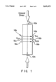
- FIG. 1 is a schematic of an experimental arrangement for measuring shear and compressional velocities in a rock sample as a function of uniaxial stress.
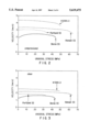
- FIG. 2 is a graph of compressional velocities as a function of uniaxial stress for three rock samples.
- FIG. 3 is a graph of shear velocities as a function of uniaxial stress for the three rock samples.
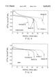
- FIG. 4 is a graph of the nonlinear parameter dV 2 /d ⁇ as a function of uniaxial stress for compressional waves measured in the three rock samples and a fourth rock sample.
- FIG. 5 is a graph of the nonlinear parameter dV 2 /d ⁇ as a function of uniaxial stress for shear waves measured in the four rock samples.
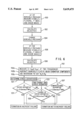
- FIG. 6 is a flow diagram of a preferred method of obtaining in situ a determination of the nonlinear parameter dV 2 /d ⁇ .
- FIG. 1 an experimental arrangement for measuring compressional and shear velocities as a function of uniaxial stress in a rock sample 21 is seen.
- the rock sample obtained were cylinders of approximately two inches in diameter, and six inches long.
- the rock samples were individually placed in a uniaxial press (not shown) which applied pressure parallel to the axis of the rock sample.
- Acoustic transducer pairs (sources and receivers) 12a, 12b, 14a, 14b, 16a, 16b, and 18a, 18b were mounted on each rock sample so that four different velocities could be measured: V P1 --compressional velocity parallel to the rock axis; V P2 --compressional velocity perpendicular to the rock axis; V S21 --shear velocity perpendicular to the rock axis and polarized parallel to the rock axis; and V S23 --shear velocity perpendicular to the rock axis and polarized perpendicular to the rock axis.
- Three sandstones Berea, Portland, Hanson), and one limestone (#1068) were measured.
- FIGS. 2 and 3 Results of the tests on the four rock samples with respect to the perpendicularly measured velocities are seen in FIGS. 2 and 3.
- FIG. 2 shows compressional velocity (V P2 ) versus uniaxial stress in the four samples, while
- FIG. 2 shows shear velocity (V S23 ) versus uniaxial stress in the four samples.
- V P2 compressional velocity
- V S23 shear velocity
- FIGS. 2 and 3 reveals that there is no correlation between rock strength and velocity, as the higher velocity limestone sample failed before a lower velocity Hanson sandstone sample, and the Portland sandstone sample failed before the lower velocity Berea sandstone sample. What is revealed in FIGS. 2 and 3, however, is that the measured velocities decreased relatively quickly just prior to failure.
- the variation in the square of the shear or compressional velocities as a function of stress is a fundamental indication of formation nonlinearity. This may also be derived from an equation for compressional velocity in a hydrostatically stressed isotropic medium set forth by Hughes, D. S. and Kelly, J. L. "Second-Order Elastic Deformation of Solids", Physical Review 92,5; p.1145 (1953):
- FIG. 4 relates to the derivatives of the perpendicular compressional wave velocities
- FIG. 5 relates to the derivatives of the shear wave velocities. As seen in FIGS. 4 and 5, the values of the derivatives drop significantly just prior to rock failure.
- a compressional derivative value of between approximately -0.15 and -0.4 (km/sec) 2 /MPa, with a preferred value of -0.2 (km/sec) 2 /MPa can be taken as a defining value of incipient failure as all the rock samples failed within about 10 MPa to 1 MPa after the compressional derivative value dropped below that value range.
- a shear derivative value of approximately -0.075 to -0.2 (km/sec) 2 /MPa, with a preferred value of -0.1 (km/sec) 2 /MPa was likewise a defining indication of incipient failure as all the rock samples failed within about 5 to 0.5 MPa after the shear derivative value dropped below that value range.
- the defining indications of incipient failure relate to the experimental arrangement of FIG. 1 where there was no overburden pressure.
- the slope of the derivative curves can be used as an indication of incipient failure as the slopes become large (negative) just prior to rock failure.
- a preferred negative slope value range defining an indication of incipient failure is between -0.02 to -0.07 (km/sec) 2 /(MPa) 2 , with a preferred value of -0.06 (km/sec) 2 /MPa 2 as rocks will typically fail if uniaxially stressed between 5--1 MPa beyond that point.
- the velocities are calculated at step 102 by a processor which is either connected to the acoustic detectors in the borehole tool, or is located uphole and coupled to the borehole tool via a wireline.
- the borehole pressure at the location of the borehole tool is changed, either by providing the borehole tool with packers which seal off that area of the borehole and a fluid injection means for increasing the pressure in the borehole, or by locating a packer type device on a well head in order to pressurize the entire borehole.
- v ref Stoneley is the velocity of the Stoneley (or flexural) wave in an unpressurized borehole (or in a borehole at a given reference pressure)
- v Stoneley is the measured velocity of the dispersive Stoneley (or flexural) wave at a known pressure
- ⁇ P is the difference in pressure between the reference pressure and the known pressure
- linear is the portion of the fractional change in the Stoneley (or flexural) dispersion caused by an increase in the borehole pressure that can be calculated from the linear constants of the formation in the ambient state
- fluid is the portion of the fractional change in the Stoneley (or flexural) dispersion caused by an increase in the borehole pressure that can be calculated from the known borehole fluid nonlinearity in the ambient state
- C l and C 2 are volume integrals which are a function of frequency and are calculable in terms of the Stoneley (or flexural) wave solution in the ambient state.
- a determination of a value for the shear derivative dV S 2 d ⁇ can be made.
- the Poisson's ratio and Young's modulus are a function of the second order constants of the formation and can be expressed by: ##EQU2##
- a plane strain approximation normal to the propagation direction is an appropriate assumption.
- the stress derivative of the shear wave polarized normal to the stress direction is given by: ##EQU3## Therefore, the stress derivative of V S23 2 can be readily approximated from either equations (8) or (11), and typically, the stress derivatives for a rock sample will fall between these approximations.
- V S23 2 the stress derivative of V S23 2 (i.e., dV S23 2 /d ⁇ ) is calculated according to equations (8) and/or (11). If the stress derivative is calculated in accordance with both sets of equations, the results may be averaged if desired.
- a desired threshold value such as -0.1 (km/sec) 2 /MPa.
- the change in the stress derivative as a function of stress can be obtained at the ambient state, and at 135, this value can be compared to another desired threshold value such as -0.06 (km/sec) 2 /MPa 2 . If the value of the change in the stress derivative as a function of stress is less than or equal to that threshold value, incipient formation failure can be declared, whereas, if the derivative of the shear derivative is greater than that threshold value, the formation can be declared to be not near failure. Further yet, if a value for the compressional derivative is obtained, that value can be compared at 137 to yet another desired threshold value such as -0.2 (km/sec) 2 /MPa.
- the compressional derivative is less than or equal to the compressional derivative threshold value, incipient formation failure can be declared, whereas if the compressional derivative is greater than the threshold value, the formation can be declared to be not near failure. Likewise, if a derivative with respect to stress of the compressional derivative is obtained, that value can be compared to the same threshold value as the derivative of the shear derivative to determine incipient formation failure.
- the threshold shear derivative value is preferably chosen between approximately -0.075 to -0.2 (km/sec) 2 /MPa, while the threshold derivative of the shear (or compressional) derivative value is preferably chosen between -0.02 to -0.07 (km/sec) 2 /(MPa) 2 .
- the threshold compressional derivative value is preferably chosen between approximately -0.15 and -0.4 (km/sec) 2 /MPa.
- yet other threshold values can be utilized.
- An alternative manner of determining the in situ value of dV 2 /d ⁇ is to take velocity measurements of only the shear and/or compressional waves at two different pressures in the borehole (the pressure relating to stress) and to deconvolve the effect the radial and hoop stress components on the change in velocity measurement.
- the slope of other indications of nonlinearity in the formation with respect to a change in stress can be used to provide an indication of incipient failure.
- indications of nonlinearity include: the amplitude of a second harmonic tube wave generated in the borehole as described in previously incorporated related application Ser. No. 08/154,645; the amplitude of an acoustic signal generated in the formation which has a frequency equal to the difference between two acoustic source signals as described in previously incorporated related application Ser. No. 08/298,919 (Docket #SDR-033) now U.S. Pat. No. 5,521,882; and the variation of velocity around the circumference of the borehole as described in previously incorporated parent application Ser. No. 08/220,717 now U.S. Pat. No. 5,544,127.
Abstract
A method for determining whether a formation is subject to incipient failure are disclosed. The method comprises determining in situ a nonlinear parameter of a formation, and determining whether the nonlinear parameter and/or a derivative of that nonlinear parameter as a function of stress has a relatively large negative value in order to determine whether the formation is subject to incipient failure. In a preferred embodiment, the nonlinear parameter of the formation is a derivative of the square of the shear or compressional velocity with respect to formation stress. The nonlinear parameter of the derivative of the square of the shear velocity with respect to stress is considered to have a large negative value when it is ≦-0.1 (km/sec)2/ MPa, while the nonlinear parameter of the derivative of the square of the compressional velocity with respect to stress is considered to have a large negative value when it is ≦-0.2 (km/sec)2 /MPa. The derivative of the derivative of the square of the shear or compressional velocity with respect to stress is considered to have a large negative value when the derivative is ≦-0.06 (km/sec)2 /(MPa)2. Typically, rocks will fail if uniaxially stressed between 11-5 MPa beyond any of those points.
Description
This application is a file wrapper continuation of parent application Ser. No. 08/298,718, filed Aug. 31, 1994, now abandoned, which is a continuation-in-part of U.S. Ser. No. 08/220,717 filed on Mar. 30, 1994, now U.S. Pat. No. 5,544,127, which is hereby incorporated by reference herein in its entirety. This application also relates to co-owned U.S. Ser. No. 08/225,016 filed Apr. 8, 1994, and now issued as U.S. Pat. No. 5,398,215, now U.S. Pat. No. 5,398,215, and co-owned U.S. Ser. No. 08/154,645 filed Nov. 19, 1993 now U.S. Pat. No. 5,485,431 which are also incorporated by reference herein in their entireties. This application further relates to co-owned U.S. Ser. Nos. 08/298,919, now U.S. Pat. No. 5,521,882 entitled Measurement of Formation Characteristics Using Acoustic Borehole Tool Having Sources of Different Frequencies" and 08/298,900, now U.S. Pat. No. 5,475,650 entitled "Measurement of Nonlinear Properties of Formation Using Sonic Borehole Tool While Changing Pressure in Borehole" which are filed on even date herewith and which are hereby incorporated by reference herein in their entireties.
1. Field of the Invention
This invention relates broadly to methods for investigating subsurface earth formations. This invention more particularly relates to methods of utilizing determinations of acoustic nonlinear formation parameters in order to determine whether a formation is in danger of collapse.
2. State of the Art
The art of sonic well logging for use in determining formation parameters is a well established art. Sonic well logs are typically derived from sonic tools suspended in a mud-filled borehole by a cable. The tools typically include a sonic source (transmitter) and a plurality of receivers which are spaced apart by several inches or feet. Typically, a sonic signal is transmitted from the transmitter at one longitudinal end of the tool and received by the receivers at the other, and measurements are made every few inches as the tool is drawn up the borehole. Depending upon the type of transmitter or source utilized (e.g., dipole, monopole), the sonic signal generated by the transmitter travels up the borehole and/or enters the formation adjacent the borehole, and the arrival times of one or more of the compressional (P-wave), shear (S-wave), Stoneley (tube wave), and flexural wave can be detected by the receivers. The receiver responses are typically processed in order to provide a time to depth conversion capability for seismic studies as well as for providing the determinations of formations parameters such as porosity.
While measurements of the compressional and shear waves are useful in quantifying and characterizing various parameters of the formation, it will be appreciated that to date, there has been no successful mechanism for making in situ determinations of nonlinear aspects of the formation; neither has there been a mechanism for interpreting measurements of nonlinear aspects of the formation. For purposes of this invention, it should be understood that the term "nonlinear" when used to describe a material relates to the fact that a plot of stress versus strain in a material will exhibit some nonlinear behavior. In particular, the strain energy function U(ε) of an isotropic elastic solid can be written as:
U(ε)=f(λ,μ)ε.sup.2 +g(α, β, γ)ε.sup.3 ( 1)
where ε is the strain, λ and μ are the second order elastic Lam e constants, and α, β, and γ are the third order elastic constants. From equation (1), it will be appreciated that the stress σ is defined by:
σ=δU/δε)=f(λ,μ)ε+g(α,.beta., γ)ε.sup.2 ( 2)
Based on equation (2) it is seen that the second order Lam e constants are linear constants, while the third order constants are nonlinear, and hence measure the nonlinearity of the material. The more nonlinear the stress versus strain plot is, the more nonlinear the material is said to be. Various manifestations of non-linearity include: the varying of the acoustic velocity in the material when the confining pressure changes; the varying of the acoustic velocity in the material when the amplitude of the acoustic wave changes; the interaction of two monochromatic acoustic beams having different frequencies to create third and fourth acoustic beams having the difference frequency and the additive frequency of the two incident beams; and evidence of frequencies being generated within the material which were not part of any input signal.
In the oil production industry, rock properties such as sanding, fracturing and borehole collapse can be considered to relate to the nonlinear properties of the formation. In each case, the strain in the rock catastrophically exceeds that which would be expected from a linear stress-strain relationship. As suggested in the parent and related applications hereto, since the less consolidated a formation is, the more nonlinear it is, a measurement of the nonlinearity of the formation can provide a measurement of the relative state of the consolidation of the formation. As suggested above, whether a layer of a formation is well or poorly consolidated, can broadly affect the producibility of the layer and formation, as well as the manner in which production is to be carried out.
It is therefore an object of the invention to determine through in situ measurements when a formation is nearing collapse.
It is another object of the invention to measure in situ nonlinear parameters of a formation and to relate the nonlinear parameters to formation failure.
It is a further object of the invention to provide a nonlinear formation parameter which is a direct indicator of formation collapse.
In accord with the objects of the invention, the method of the invention broadly comprises determining in situ a nonlinear parameter of a formation, and determining whether the nonlinear parameter and/or the slope of a curve of that nonlinear parameter as a function of stress has a relatively large negative value in order to determine whether the formation is subject to incipient failure. In a preferred embodiment, the nonlinear parameter of the formation is either a derivative of the square of the shear velocity with respect to formation stress, or a derivative of the square of the compressional velocity with respect to stress.
A preferred method of determining the nonlinear parameter of the formation (i.e., the derivative of the square of the shear velocity), is set forth in the previously incorporated related application Ser. No. 08/298,900, now U.S. Pat. No. 5,475,650. Briefly, velocity measurements of Stoneley and/or flexural waves, and shear and compressional waves are taken at two different pressures in the borehole, and the measurements are used in order to find values for the nonlinear parameters N1 and N2 which are related to the desired nonlinear parameter according to equations set forth in that related application. Alternatively, it is possible to take velocity measurements of only the shear and/or compressional waves at two different pressures in the borehole (the pressure relating to stress) and to deconvolve the effect the radial and hoop stress components on the change in velocity measurement.
According to other aspects of the invention, the slope of other indications of nonlinearity in the formation with respect to a change in stress can be used to provide an indication of incipient failure. Such indications of nonlinearity include: the amplitude of a second harmonic tube wave generated in the borehole as described in previously incorporated related application Ser. No. 08/154,645 now U.S. Pat. No. 5,485,431; the amplitude of an acoustic signal generated in the formation which has a frequency equal to the difference between two acoustic source signals as described in previously incorporated related application Ser. No. 08/298,919, now U.S. Pat. No. 5,521,882; and the variation of velocity around the circumference of the borehole as described in previously incorporated parent application Ser. No. 08/220,717 now U.S. Pat. No. 5,544,127.
Additional objects and advantages of the invention will become apparent to those skilled in the art upon reference to the detailed description taken in conjunction with the provided figures.
FIG. 1 is a schematic of an experimental arrangement for measuring shear and compressional velocities in a rock sample as a function of uniaxial stress.
FIG. 2 is a graph of compressional velocities as a function of uniaxial stress for three rock samples.
FIG. 3 is a graph of shear velocities as a function of uniaxial stress for the three rock samples.
FIG. 4 is a graph of the nonlinear parameter dV2 /dσ as a function of uniaxial stress for compressional waves measured in the three rock samples and a fourth rock sample.
FIG. 5 is a graph of the nonlinear parameter dV2 /dσ as a function of uniaxial stress for shear waves measured in the four rock samples.
FIG. 6 is a flow diagram of a preferred method of obtaining in situ a determination of the nonlinear parameter dV2 /dσ.
Turning to FIG. 1, an experimental arrangement for measuring compressional and shear velocities as a function of uniaxial stress in a rock sample 21 is seen. The rock sample obtained were cylinders of approximately two inches in diameter, and six inches long. The rock samples were individually placed in a uniaxial press (not shown) which applied pressure parallel to the axis of the rock sample. Acoustic transducer pairs (sources and receivers) 12a, 12b, 14a, 14b, 16a, 16b, and 18a, 18b were mounted on each rock sample so that four different velocities could be measured: VP1 --compressional velocity parallel to the rock axis; VP2 --compressional velocity perpendicular to the rock axis; VS21 --shear velocity perpendicular to the rock axis and polarized parallel to the rock axis; and VS23 --shear velocity perpendicular to the rock axis and polarized perpendicular to the rock axis. Three sandstones (Berea, Portland, Hanson), and one limestone (#1068) were measured. For each rock sample, uniaxial stress was increased by the press in increments until the rock eventually fractured. At each stress increment all four velocities were measured, although the velocities measured perpendicular to the applied stress (VP2 and VS23) were of most interest because they are believed to be most relevant to borehole failure caused by external stresses applied perpendicular to the borehole axis.
Results of the tests on the four rock samples with respect to the perpendicularly measured velocities are seen in FIGS. 2 and 3. FIG. 2 shows compressional velocity (VP2) versus uniaxial stress in the four samples, while FIG. 2 shows shear velocity (VS23) versus uniaxial stress in the four samples. A review of FIGS. 2 and 3 reveals that there is no correlation between rock strength and velocity, as the higher velocity limestone sample failed before a lower velocity Hanson sandstone sample, and the Portland sandstone sample failed before the lower velocity Berea sandstone sample. What is revealed in FIGS. 2 and 3, however, is that the measured velocities decreased relatively quickly just prior to failure. This decrease is believed to result from dilatancy in the rock sample which is the opening of microcracks caused by increasing non-hydrostatic stresses. Dilatancy has previously been studied in igneous rocks in relation to earthquake prediction, and was also observed in unconsolidated sand. See Nur, A. "A Note on the Constitutive Law for Dilatancy", Pageoph, Vol. 113 (1975).
As set forth in the related cases hereto, the variation in the square of the shear or compressional velocities as a function of stress is a fundamental indication of formation nonlinearity. This may also be derived from an equation for compressional velocity in a hydrostatically stressed isotropic medium set forth by Hughes, D. S. and Kelly, J. L. "Second-Order Elastic Deformation of Solids", Physical Review 92,5; p.1145 (1953):
ρ.sub.0 V.sub.P.sup.2 λ+2μ-(P/3K)[61+4m+7+10μ](3)
where ρ0 is the mass density of the formation, VP is the compressional wave velocity, P is the applied pressure, λ and μ are the Lam e constants, and l and m are third order (nonlinear) elastic constants. From equation (3), it can be seen that the compressional velocity squared, as a function of stress (via hydrostatic pressure P) is directly proportional to the nonlinear constants l and m (and the linear Lame constants). Based on equation (3), and recognizing that the nonlinear coefficients l and m are typically at least two orders of magnitude greater than the linear coefficients, it will be appreciated that if the velocity does not significantly vary with stress, the rock is considered to be linear. However, if the velocity does significantly vary with stress, the rock can be described as having nonlinear characteristics. Thus, the derivative of the square of the velocity as a function of stress may be considered a direct indication of formation nonlinearity.
Using the data obtained with reference to FIGS. 2 and 3, values were derived and plotted of the derivative with respect to stress of the square of the velocity (dV2 /dσ) as a function of stress as seen in FIGS. 4 and 5. FIG. 4 relates to the derivatives of the perpendicular compressional wave velocities, while FIG. 5 relates to the derivatives of the shear wave velocities. As seen in FIGS. 4 and 5, the values of the derivatives drop significantly just prior to rock failure. In fact, it can be seen that a compressional derivative value of between approximately -0.15 and -0.4 (km/sec)2 /MPa, with a preferred value of -0.2 (km/sec)2 /MPa can be taken as a defining value of incipient failure as all the rock samples failed within about 10 MPa to 1 MPa after the compressional derivative value dropped below that value range. Likewise, a shear derivative value of approximately -0.075 to -0.2 (km/sec)2 /MPa, with a preferred value of -0.1 (km/sec)2 /MPa was likewise a defining indication of incipient failure as all the rock samples failed within about 5 to 0.5 MPa after the shear derivative value dropped below that value range. It should be appreciated that the defining indications of incipient failure relate to the experimental arrangement of FIG. 1 where there was no overburden pressure. Thus, it is possible that in the formation different values for defining indications of incipient failure will be obtained.
It will also be appreciated that the slope of the derivative curves can be used as an indication of incipient failure as the slopes become large (negative) just prior to rock failure. A preferred negative slope value range defining an indication of incipient failure is between -0.02 to -0.07 (km/sec)2 /(MPa)2, with a preferred value of -0.06 (km/sec)2 /MPa2 as rocks will typically fail if uniaxially stressed between 5--1 MPa beyond that point. Again it is noted that these values relate to the experimental arrangement of FIG. 1, and that it is possible that via experimentation in the borehole, other values might be found in formations with overburden pressures.
A preferred manner of determining the derivative of the shear velocity squared with respect to stress (dVX 2 /dσ) is set forth in previously incorporated related patent application Ser. No. 08/298,900, now U.S. Pat. No. 5,475,650. However, for purposes of completeness, a brief review is included herein. Thus, as seen in FIG. 6, using a borehole tool having a monopole and/or dipole source and acoustic detectors, at 100 the velocity of Stoneley and/or flexural waves, and compressional and shear waves generated by the source(s) are measured. The velocities (including velocity dispersion curves for the Stoneley and flexural waves) are calculated at step 102 by a processor which is either connected to the acoustic detectors in the borehole tool, or is located uphole and coupled to the borehole tool via a wireline. At 104, the borehole pressure at the location of the borehole tool is changed, either by providing the borehole tool with packers which seal off that area of the borehole and a fluid injection means for increasing the pressure in the borehole, or by locating a packer type device on a well head in order to pressurize the entire borehole. Then at 106, at the second pressure, Stoneley and/or flexural waves, and compressional and shear waves are generated and measured again, and at 108, wave velocities at the second pressure are calculated. Using the change in Stoneley and/or flexural wave velocities, as well as the p-wave and s-wave velocities, values for the nonlinear formation parameters N1 and N2 are found at step 112. In particular, for each of at least two frequencies (at least one of which is preferably in the 3 kHz to 6 kHz range), a fractional change in the measured acoustic velocity is made at step 112a. From the fractional change, a component generated by the borehole fluid and a component due to linear aspects of the formation are subtracted at step 112b to provide a frequency dependent nonlinear formation component (B). Then, utilizing an inversion process AX=B at step 112c according to the following equations (4)-(7), values are obtained for the nonlinear parameters N1 and N2 :
A=|C.sub.1.sup.f1 C.sub.2.sup.f1 | |C.sub.1.sup.f2 C.sub.2.sup.f2| (4)
X=|N.sub.1 ΔP| |N.sub.2 ΔP|(5)
B=|(Δv/v|.sub.Stoneley -Δv/v|.sub.linearl -Δv/v|.sub.fluid).sub.fl | |(Δv/v|.sub.Stoneley -Δv/v|.sub.linear -Δv/v|.sub.fluid).sub.f2 | (6)
where
Δv/v |.sub.Stoneley =(v.sup.Stoneley -v.sub.ref.sup.Stoneley)/v.sub.ref .sup.Stoneley (7)
and where vref Stoneley is the velocity of the Stoneley (or flexural) wave in an unpressurized borehole (or in a borehole at a given reference pressure), vStoneley is the measured velocity of the dispersive Stoneley (or flexural) wave at a known pressure, ΔP is the difference in pressure between the reference pressure and the known pressure, Δv/v|linear is the portion of the fractional change in the Stoneley (or flexural) dispersion caused by an increase in the borehole pressure that can be calculated from the linear constants of the formation in the ambient state, Δv/v|fluid is the portion of the fractional change in the Stoneley (or flexural) dispersion caused by an increase in the borehole pressure that can be calculated from the known borehole fluid nonlinearity in the ambient state, and Cl and C2 are volume integrals which are a function of frequency and are calculable in terms of the Stoneley (or flexural) wave solution in the ambient state. Additional details may be found in related patent application Ser. No. 08/298,900, now U.S. Pat. No. 5,475,650 regarding the volume integrals, as well as the fractional changes in the Stoneley or flexural dispersions caused the increase in the borehole pressure due to the linear constants of the formation and due to the borehole fluid nonlinearity.
With values determined for nonlinear parameters Nl and N2, a determination of a value for the shear derivative dVS 2 dσ can be made. In particular, as set forth in the related patent application Ser. No. 08/298,900, where a specimen is in the form of a rod with uniaxial stress applied along the rod axis (i.e., stresses normal to the rod axis are assumed to be zero), a stress derivative of the shear waves propagating normal to the rod axis and polarized normal to the stress direction can be approximated by: ##EQU1## where N1 =-c144 /c66 and N2 =-c155 /c66, and λ and Y are respectively Poisson's ratio and Young's modulus in the formation in the reference ambient state. The Poisson's ratio and Young's modulus are a function of the second order constants of the formation and can be expressed by: ##EQU2## On the other hand, if the specimen is long along the propagation direction, a plane strain approximation normal to the propagation direction is an appropriate assumption. In this case, the stress derivative of the shear wave polarized normal to the stress direction is given by: ##EQU3## Therefore, the stress derivative of VS23 2 can be readily approximated from either equations (8) or (11), and typically, the stress derivatives for a rock sample will fall between these approximations. Thus, at 121 of FIG. 6, the stress derivative of VS23 2 (i.e., dVS23 2 /dσ) is calculated according to equations (8) and/or (11). If the stress derivative is calculated in accordance with both sets of equations, the results may be averaged if desired.
As set forth above, once a value for the stress derivative is calculated, a determination can be made as to whether the formation is in danger of incipient failure. For example, as suggested at 131 of FIG. 6, the determined value of the shear derivative can be compared to a desired threshold value such as -0.1 (km/sec)2 /MPa. If the shear derivative is less than or equal to the desired threshold value, incipient formation failure can be declared; whereas, if the shear derivative is greater than the threshold value, the formation can be declared to be not near failure. Alternatively, or in addition, at 133, the change in the stress derivative as a function of stress can be obtained at the ambient state, and at 135, this value can be compared to another desired threshold value such as -0.06 (km/sec)2 /MPa2. If the value of the change in the stress derivative as a function of stress is less than or equal to that threshold value, incipient formation failure can be declared, whereas, if the derivative of the shear derivative is greater than that threshold value, the formation can be declared to be not near failure. Further yet, if a value for the compressional derivative is obtained, that value can be compared at 137 to yet another desired threshold value such as -0.2 (km/sec)2 /MPa. Again, if the compressional derivative is less than or equal to the compressional derivative threshold value, incipient formation failure can be declared, whereas if the compressional derivative is greater than the threshold value, the formation can be declared to be not near failure. Likewise, if a derivative with respect to stress of the compressional derivative is obtained, that value can be compared to the same threshold value as the derivative of the shear derivative to determine incipient formation failure.
It will be appreciated that, if desired, other threshold values can be utilized. For example, the threshold shear derivative value is preferably chosen between approximately -0.075 to -0.2 (km/sec)2 /MPa, while the threshold derivative of the shear (or compressional) derivative value is preferably chosen between -0.02 to -0.07 (km/sec)2 /(MPa)2. The threshold compressional derivative value is preferably chosen between approximately -0.15 and -0.4 (km/sec)2 /MPa. However, yet other threshold values can be utilized.
An alternative manner of determining the in situ value of dV2 /dσ is to take velocity measurements of only the shear and/or compressional waves at two different pressures in the borehole (the pressure relating to stress) and to deconvolve the effect the radial and hoop stress components on the change in velocity measurement.
According to other aspects of the invention, the slope of other indications of nonlinearity in the formation with respect to a change in stress (i.e., the derivative with respect to stress) can be used to provide an indication of incipient failure. Such indications of nonlinearity include: the amplitude of a second harmonic tube wave generated in the borehole as described in previously incorporated related application Ser. No. 08/154,645; the amplitude of an acoustic signal generated in the formation which has a frequency equal to the difference between two acoustic source signals as described in previously incorporated related application Ser. No. 08/298,919 (Docket #SDR-033) now U.S. Pat. No. 5,521,882; and the variation of velocity around the circumference of the borehole as described in previously incorporated parent application Ser. No. 08/220,717 now U.S. Pat. No. 5,544,127.
There have been described and illustrated herein methods for predicting mechanical failure in formations. While particular embodiments have been described, it is not intended that the invention be limited thereto, as it is intended that the invention be as broad in scope as the art will allow and that the specification be read likewise. Thus, while particular preferred stress and compressional derivative threshold values and ranges were provided for determining whether a formation is in incipient failure, it will be appreciated that other thresholds could be utilized. Also, while preferred methods of obtaining in situ values for the derivative with respect to stress of the square of the shear velocity (dVS 2 /dσ) were described, it will be appreciated that other methods could be utilized within the scope of the invention. It will therefore be appreciated by those skilled in the art that yet other modifications could be made to the provided invention without deviating from its spirit and scope as so claimed.
Claims (17)
1. A method for determining in situ incipient stress failure of an underground formation traversed by a borehole, comprising:
(a) positioning a tool having an acoustic source and at least one receiver in the borehole near the formation;
(b) transmitting an acoustic signal from the source into the formation and detecting the signal with the at least one receiver after it has propagated through the formation;
(c) determining, from the received signal, at least one of a compressional wave velocity and a shear wave velocity;
(d) determining, from at least one of the compressional wave velocity and the shear wave velocity, a value of a non-linear parameter of the formation; and
(e) comparing the value of the non-linear parameter with a threshold value so as to determine incipient stress failure of the formation.
2. A method as claimed in claim 1, wherein the non-linear parameter is a derivative of squared shear velocity with respect to formation stress.
3. A method as claimed in claim 2, wherein the threshold value is chosen from the range -0.075 (km/sec)2 /MPa to -0.2 (km/sec)2 /MPa.
4. A method as claimed in claim 3, wherein the threshold value is about -0.1 (km/sec)2 /MPa.
5. A method as claimed in claim 1, wherein the non-linear parameter is a derivative of squared compressional velocity with respect to formation stress.
6. A method as claimed in claim 5, wherein the threshold value is chosen from the range -0.15 (km/sec)2 /MPa to -0.4 (km/sec)2 /MPa.
7. A method as claimed in claim 6, wherein the threshold value is about -0.2 (km/sec)2 /MPa.
8. A method as claimed in claim 5, wherein the parameter is a non-linear parameter comprising at least one of a derivative of squared shear velocity with respect to formation stress, and a derivative of squared compressional velocity with respect to formation stress, and a derivative of squared compressional velocity with respect to formation stress.
9. A method as claimed in claim 8, wherein the threshold value is chosen from the range -0.02 (km/sec)2 /MPa to -0.07 (km/sec.)2 /MPa.
10. A method as claimed in claim 9, wherein the threshold value is about -0.06 (km/sec)2 /(MPa)2.
11. A method for determining in situ incipient stress failure of an underground formation traversed by a borehole, comprising:
(a) positioning a tool having an acoustic source and at least one receiver in the borehole near the formation;
(b) transmitting an acoustic signal from the source into the formation and detecting the signal with the at least one receiver after it has propagated through the formation;
(c) determining, from the received signal, at least one of a compressional wave velocity and a shear wave velocity;
(d) determining, from at least one of the compressional wave velocity and the shear wave velocity, a value of a parameter indicative of non-linearity of a relationship between formation strain as defined by a strain energy function U(ε)=f(λ/μ)ε2 +g(α, β,γ)ε3, wherein e is the strain, l and m are second order elastic Lame constants, and formation stress as defined by σ=δU/δε=f(λ, μ)ε+g(α, β, γ)ε2 ; and
(e) comparing the value of the parameter indicative of non-linearity with a threshold value so as to determine incipient stress failure of the formation.
12. A method as claimed in claim 11, further comprising determining at least one of sanding, fracturing and borehole collapse.
13. A method as claimed in claim 11, further comprising determining a degree of relative consolidation of the formation.
14. A method as claimed in claim 11, further comprising determining a parameter related to the producibility of fluids from the formation into the borehole.
15. A method as claimed in claim 11, further comprising using the value to and the comparison to determine a manner in which fluids are produced from the formation.
16. A method as claimed in claim 1, wherein the steps of transmitting and receiving the acoustic signal are repeated at two different pressures in the borehole so as to determine values of the parameter at these pressures.
17. A method as claimed in claim 11, further comprising determining at least one of Stoneley velocity and flexural velocity.
Priority Applications (1)
| Application Number | Priority Date | Filing Date | Title |
|---|---|---|---|
| US08/555,796 US5619475A (en) | 1994-03-30 | 1995-11-09 | Method of predicting mechanical failure in formation utilizing stress derivatives which measure formation nonlinearity |
Applications Claiming Priority (3)
| Application Number | Priority Date | Filing Date | Title |
|---|---|---|---|
| US08/220,717 US5544127A (en) | 1994-03-30 | 1994-03-30 | Borehole apparatus and methods for measuring formation velocities as a function of azimuth, and interpretation thereof |
| US29871894A | 1994-08-31 | 1994-08-31 | |
| US08/555,796 US5619475A (en) | 1994-03-30 | 1995-11-09 | Method of predicting mechanical failure in formation utilizing stress derivatives which measure formation nonlinearity |
Related Parent Applications (1)
| Application Number | Title | Priority Date | Filing Date |
|---|---|---|---|
| US29871894A Continuation | 1994-03-30 | 1994-08-31 |
Publications (1)
| Publication Number | Publication Date |
|---|---|
| US5619475A true US5619475A (en) | 1997-04-08 |
Family
ID=26915122
Family Applications (1)
| Application Number | Title | Priority Date | Filing Date |
|---|---|---|---|
| US08/555,796 Expired - Lifetime US5619475A (en) | 1994-03-30 | 1995-11-09 | Method of predicting mechanical failure in formation utilizing stress derivatives which measure formation nonlinearity |
Country Status (1)
| Country | Link |
|---|---|
| US (1) | US5619475A (en) |
Cited By (19)
| Publication number | Priority date | Publication date | Assignee | Title |
|---|---|---|---|---|
| USRE36181E (en) * | 1993-06-30 | 1999-04-06 | United Technologies Automotive, Inc. | Pseudorandom number generation and crytographic authentication |
| USRE36752E (en) * | 1993-06-30 | 2000-06-27 | United Technologies Automotive, Inc. | Cryptographic authentication of transmitted messages using pseudorandom numbers |
| GB2351350A (en) * | 1999-06-23 | 2000-12-27 | Sofitech Nv | Cavity stability prediction method for wellbores |
| US6188961B1 (en) * | 1999-03-31 | 2001-02-13 | Hilliburton Energy Services, Inc. | Acoustic logging apparatus and method |
| US6351991B1 (en) * | 2000-06-05 | 2002-03-05 | Schlumberger Technology Corporation | Determining stress parameters of formations from multi-mode velocity data |
| US20070288170A1 (en) * | 2005-08-08 | 2007-12-13 | Schlumberger Technology Corporation | Method and system for pre-drill pore pressure prediction |
| US20090248312A1 (en) * | 2008-03-31 | 2009-10-01 | Sheng-Yuan Hsu | Integration of geomechanics and seismic analysis for passive seismic feasibility analysis |
| WO2010047858A1 (en) * | 2008-10-20 | 2010-04-29 | Exxonmobil Upstream Research Company | Method for predicting time-lapse seismic timeshifts by computer simulation |
| US20110015907A1 (en) * | 2009-07-20 | 2011-01-20 | Crawford Brian R | Petrophysical Method For Predicting Plastic Mechanical Properties In Rock Formations |
| US20110166843A1 (en) * | 2007-08-24 | 2011-07-07 | Sheng-Yuan Hsu | Method For Modeling Deformation In Subsurface Strata |
| US20110170373A1 (en) * | 2007-08-24 | 2011-07-14 | Sheng-Yuan Hsu | Method For Predicting Time-Lapse Seismic Timeshifts By Computer Simulation |
| WO2012173924A2 (en) * | 2011-06-13 | 2012-12-20 | Shell Oil Company | Hydraulic fracture monitoring using active seismic sources with receivers in the treatment well |
| CN104089695A (en) * | 2014-07-04 | 2014-10-08 | 南华大学 | Method for measuring spreading speed of stress waves in anchor rod |
| US9411071B2 (en) | 2012-08-31 | 2016-08-09 | Exxonmobil Upstream Research Company | Method of estimating rock mechanical properties |
| US20170131192A1 (en) * | 2015-11-06 | 2017-05-11 | Baker Hughes Incorporated | Determining the imminent rock failure state for improving multi-stage triaxial compression tests |
| US20170370798A1 (en) * | 2015-08-31 | 2017-12-28 | Globiz Co., Ltd. | Large space structure collapse detection apparatus and collapse detection method using the same |
| US20180058212A1 (en) * | 2015-11-06 | 2018-03-01 | Baker Hughes, A Ge Company, Llc | Determining the Imminent Rock Failure State for Improving Multi-Stage Triaxial Compression Tests |
| US10048403B2 (en) | 2013-06-20 | 2018-08-14 | Exxonmobil Upstream Research Company | Method and system for generation of upscaled mechanical stratigraphy from petrophysical measurements |
| US10317556B2 (en) * | 2016-01-25 | 2019-06-11 | Baker Hughes, A Ge Company, Llc | Non-linear acoustic formation evaluation |
Citations (5)
| Publication number | Priority date | Publication date | Assignee | Title |
|---|---|---|---|---|
| US4052889A (en) * | 1976-06-10 | 1977-10-11 | Adaptronics, Inc. | System for measurement of subsurface fatigue crack size |
| US4399525A (en) * | 1979-10-05 | 1983-08-16 | Chevron Research Company | Method for interpreting well log records to yield indications of gas/oil in an earth formation such as a sandstone, limestone, or dolostone |
| US4951264A (en) * | 1986-05-16 | 1990-08-21 | University Of Miami | Method of measuring the shear modulus profile of a seabed |
| USH1156H (en) * | 1991-11-21 | 1993-03-02 | Downhole fracture detection and characterization | |
| US5353637A (en) * | 1992-06-09 | 1994-10-11 | Plumb Richard A | Methods and apparatus for borehole measurement of formation stress |
-
1995
- 1995-11-09 US US08/555,796 patent/US5619475A/en not_active Expired - Lifetime
Patent Citations (5)
| Publication number | Priority date | Publication date | Assignee | Title |
|---|---|---|---|---|
| US4052889A (en) * | 1976-06-10 | 1977-10-11 | Adaptronics, Inc. | System for measurement of subsurface fatigue crack size |
| US4399525A (en) * | 1979-10-05 | 1983-08-16 | Chevron Research Company | Method for interpreting well log records to yield indications of gas/oil in an earth formation such as a sandstone, limestone, or dolostone |
| US4951264A (en) * | 1986-05-16 | 1990-08-21 | University Of Miami | Method of measuring the shear modulus profile of a seabed |
| USH1156H (en) * | 1991-11-21 | 1993-03-02 | Downhole fracture detection and characterization | |
| US5353637A (en) * | 1992-06-09 | 1994-10-11 | Plumb Richard A | Methods and apparatus for borehole measurement of formation stress |
Non-Patent Citations (31)
| Title |
|---|
| A Note on the Constitutive Law for Dilantance by Nur, Pageoph, vol. 113 (1975) pp. 197 206. * |
| A Note on the Constitutive Law for Dilantance by Nur, Pageoph, vol. 113 (1975) pp. 197-206. |
| Acoustic Character Logs and Their Applications in Formation Evaluation by Pickett, Jour. of petroleum Technology vol. 15, pp. 659 667 (1963). * |
| Acoustic Character Logs and Their Applications in Formation Evaluation by Pickett, Jour. of petroleum Technology vol. 15, pp. 659-667 (1963). |
| Borehole Flexural modes in anisotropic formations, by Sinha et al., Geophysics vol., 59, No. 7, Jul. 1994 pp. 1037 1052 * |
| Borehole Flexural modes in anisotropic formations, by Sinha et al., Geophysics vol., 59, No. 7, Jul. 1994 pp. 1037-1052 |
| Earth Planetary Inferiors, Sal. 50, 1, pp. 1 7, Jan. 1988; abstract only provided herewith. * |
| Earth Planetary Inferiors, Sal. 50,#1, pp. 1-7, Jan. 1988; abstract only provided herewith. |
| Effects of porosity and clay content on wave velocities in sandstones, by Han et al., Geophysics, vol. 51 No. 11, Nov. 1986 pp. 2093 2107. * |
| Effects of porosity and clay content on wave velocities in sandstones, by Han et al., Geophysics, vol. 51 No. 11, Nov. 1986 pp. 2093-2107. |
| Hughes et al, Physical Review, vol. 92, 5, Dec. 1, 1953, pp. 1145 1149. * |
| Hughes et al, Physical Review, vol. 92,#5, Dec. 1, 1953, pp. 1145-1149. |
| Miles et al, Petroleum Technology, Nov. 1948, pp. 186 191. * |
| Miles et al, Petroleum Technology, Nov. 1948, pp. 186-191. |
| Nikolaew, A. R.; IA SPIE I Nonlinear Seismal. Int. Symp (Suzdal USSR Oct. 31, 1986), Phys. * |
| Numverical Computation of individual far field arrivals excited by an acoustic source in a borehole by Kurkjian, Geophysics vol. 50, No. 5, May 1985, pp. 852 866. * |
| Numverical Computation of individual far-field arrivals excited by an acoustic source in a borehole by Kurkjian, Geophysics vol. 50, No. 5, May 1985, pp. 852-866. |
| Relationship between compressional wave and shear wave velocities in clastic silicate rocks by Castagna et al. Geophysics, vol. 50, No. 4, Apr. 1985 pp. 571 581. * |
| Relationship between compressional-wave and shear-wave velocities in clastic silicate rocks by Castagna et al. Geophysics, vol. 50, No. 4, Apr. 1985 pp. 571-581. |
| Second Order Elastic Deformation of Solids by Hughes et al. Physical Review, vol. 92, No. 5, Dec. 1953, pp. 1145 1149. * |
| Second-Order Elastic Deformation of Solids by Hughes et al. Physical Review, vol. 92, No. 5, Dec. 1953, pp. 1145-1149. |
| Sergio Kostek, PHD Thesis, MIT, Apr. 1993, "Linear and Nonlinear Electric Wave Propagation in a Fluid Filled Borehole"; pp. 1-187. |
| Sergio Kostek, PHD Thesis, MIT, Apr. 1993, Linear and Nonlinear Electric Wave Propagation in a Fluid Filled Borehole ; pp. 1 187. * |
| Sound Waves in Deformed Perfectly Elastic Materials, Acoustoelastic Effect by Toupin et al., Jour. of Acoustical Society of America, vol. 33, No. 2, Feb. 1961, pp. 216 225. * |
| Sound Waves in Deformed Perfectly Elastic Materials, Acoustoelastic Effect by Toupin et al., Jour. of Acoustical Society of America, vol. 33, No. 2, Feb. 1961, pp. 216-225. |
| Third order Elastic Constants and the Velocity of Small Amplitude Elastic Waves in Homogeneously Stressed Media by Thurston et al. Physical Review, vol. 133, No. 6A Mar. 1964, pp. A1604 1610. * |
| Third order elastic constants for an inviscid fluid, by Kostek et al., Jour. Acoust. Soc. Am. 94(5) Nov. 1993 pp. 3014 3017. * |
| Third-order Elastic Constants and the Velocity of Small Amplitude Elastic Waves in Homogeneously Stressed Media by Thurston et al. Physical Review, vol. 133, No. 6A Mar. 1964, pp. A1604-1610. |
| Third-order elastic constants for an inviscid fluid, by Kostek et al., Jour. Acoust. Soc. Am. 94(5) Nov. 1993 pp. 3014-3017. |
| Velocity Porosity Clay Content Systematics of Poorly Consolidated Sandstones by Kowallis et al., Jour. of Geophysical Research, vol., 89, No. B12, pp. 10,355 10,364, Nov. 10, 1984. * |
| Velocity-Porosity-Clay Content Systematics of Poorly Consolidated Sandstones by Kowallis et al., Jour. of Geophysical Research, vol., 89, No. B12, pp. 10,355-10,364, Nov. 10, 1984. |
Cited By (30)
| Publication number | Priority date | Publication date | Assignee | Title |
|---|---|---|---|---|
| USRE36752E (en) * | 1993-06-30 | 2000-06-27 | United Technologies Automotive, Inc. | Cryptographic authentication of transmitted messages using pseudorandom numbers |
| USRE36181E (en) * | 1993-06-30 | 1999-04-06 | United Technologies Automotive, Inc. | Pseudorandom number generation and crytographic authentication |
| US6188961B1 (en) * | 1999-03-31 | 2001-02-13 | Hilliburton Energy Services, Inc. | Acoustic logging apparatus and method |
| GB2351350A (en) * | 1999-06-23 | 2000-12-27 | Sofitech Nv | Cavity stability prediction method for wellbores |
| GB2351350B (en) * | 1999-06-23 | 2001-09-12 | Sofitech Nv | Cavity stability prediction method for wellbores |
| US7066019B1 (en) | 1999-06-23 | 2006-06-27 | Schlumberger Technology Corporation | Cavity stability prediction method for wellbores |
| US6351991B1 (en) * | 2000-06-05 | 2002-03-05 | Schlumberger Technology Corporation | Determining stress parameters of formations from multi-mode velocity data |
| US7617051B2 (en) | 2005-08-08 | 2009-11-10 | Schlumberger Technology Corporation | Method and system for pre-drill pore pressure prediction |
| US20070288170A1 (en) * | 2005-08-08 | 2007-12-13 | Schlumberger Technology Corporation | Method and system for pre-drill pore pressure prediction |
| US9164194B2 (en) | 2007-08-24 | 2015-10-20 | Sheng-Yuan Hsu | Method for modeling deformation in subsurface strata |
| US8768672B2 (en) | 2007-08-24 | 2014-07-01 | ExxonMobil. Upstream Research Company | Method for predicting time-lapse seismic timeshifts by computer simulation |
| US8548782B2 (en) | 2007-08-24 | 2013-10-01 | Exxonmobil Upstream Research Company | Method for modeling deformation in subsurface strata |
| US20110166843A1 (en) * | 2007-08-24 | 2011-07-07 | Sheng-Yuan Hsu | Method For Modeling Deformation In Subsurface Strata |
| US20110170373A1 (en) * | 2007-08-24 | 2011-07-14 | Sheng-Yuan Hsu | Method For Predicting Time-Lapse Seismic Timeshifts By Computer Simulation |
| US8121792B2 (en) * | 2008-03-31 | 2012-02-21 | Exxonmobil Upstream Research Co. | Integration of geomechanics and seismic analysis for passive seismic feasibility analysis |
| US20090248312A1 (en) * | 2008-03-31 | 2009-10-01 | Sheng-Yuan Hsu | Integration of geomechanics and seismic analysis for passive seismic feasibility analysis |
| WO2010047858A1 (en) * | 2008-10-20 | 2010-04-29 | Exxonmobil Upstream Research Company | Method for predicting time-lapse seismic timeshifts by computer simulation |
| US8498853B2 (en) | 2009-07-20 | 2013-07-30 | Exxonmobil Upstream Research Company | Petrophysical method for predicting plastic mechanical properties in rock formations |
| US20110015907A1 (en) * | 2009-07-20 | 2011-01-20 | Crawford Brian R | Petrophysical Method For Predicting Plastic Mechanical Properties In Rock Formations |
| WO2012173924A2 (en) * | 2011-06-13 | 2012-12-20 | Shell Oil Company | Hydraulic fracture monitoring using active seismic sources with receivers in the treatment well |
| WO2012173924A3 (en) * | 2011-06-13 | 2013-04-25 | Shell Oil Company | Hydraulic fracture monitoring using active seismic sources with receivers in the treatment well |
| US9347313B2 (en) | 2011-06-13 | 2016-05-24 | Shell Oil Company | Hydraulic fracture monitoring using active seismic sources with receivers in the treatment well |
| US9411071B2 (en) | 2012-08-31 | 2016-08-09 | Exxonmobil Upstream Research Company | Method of estimating rock mechanical properties |
| US10048403B2 (en) | 2013-06-20 | 2018-08-14 | Exxonmobil Upstream Research Company | Method and system for generation of upscaled mechanical stratigraphy from petrophysical measurements |
| CN104089695A (en) * | 2014-07-04 | 2014-10-08 | 南华大学 | Method for measuring spreading speed of stress waves in anchor rod |
| US20170370798A1 (en) * | 2015-08-31 | 2017-12-28 | Globiz Co., Ltd. | Large space structure collapse detection apparatus and collapse detection method using the same |
| US20180058212A1 (en) * | 2015-11-06 | 2018-03-01 | Baker Hughes, A Ge Company, Llc | Determining the Imminent Rock Failure State for Improving Multi-Stage Triaxial Compression Tests |
| US20170131192A1 (en) * | 2015-11-06 | 2017-05-11 | Baker Hughes Incorporated | Determining the imminent rock failure state for improving multi-stage triaxial compression tests |
| US10385687B2 (en) * | 2015-11-06 | 2019-08-20 | Baker Hughes, A Ge Company, Llc | Determining the imminent rock failure state for improving multi-stage triaxial compression tests |
| US10317556B2 (en) * | 2016-01-25 | 2019-06-11 | Baker Hughes, A Ge Company, Llc | Non-linear acoustic formation evaluation |
Similar Documents
| Publication | Publication Date | Title |
|---|---|---|
| US5619475A (en) | Method of predicting mechanical failure in formation utilizing stress derivatives which measure formation nonlinearity | |
| US5475650A (en) | Measurement of nonlinear properties of formation using sonic borehole tool while changing pressure in borehole | |
| US5838633A (en) | Method for estimating formation in-situ stress magnitudes using a sonic borehole tool | |
| US5521882A (en) | Measurement of formation characteristics using acoustic borehole tool having sources of different frequencies | |
| US9176250B2 (en) | Estimation of depletion or injection induced reservoir stresses using time-lapse sonic data in cased holes | |
| CA2323676C (en) | Formation stress identification and estimation using borehole monopole and cross-dipole acoustic measurements | |
| US5398215A (en) | Identification of stress induced anisotropy in formations | |
| EP3529641B1 (en) | Downhole nonlinear acoustics measurements in rock formations using dynamic acoustic elasticity and time reversal | |
| McCann et al. | Determination of Young’s modulus of the rock mass from geophysical well logs | |
| Gholami et al. | Application of in situ stress estimation methods in wellbore stability analysis under isotropic and anisotropic conditions | |
| US5485431A (en) | Measurement of nonlinear formation parameters using sonic borehole tool | |
| Starzec | Dynamic elastic properties of crystalline rocks from south-west Sweden | |
| Fjaer et al. | Rock mechanics and rock acoustics | |
| Marsala et al. | Sonic while drilling: Have you thought about cuttings? | |
| Al-Malikee et al. | Indirect prediction of rock elasticity and compressibility strength using well log data at selected sites within Rumaila Oilfield, Southern Iraq | |
| GB2293652A (en) | Predicting mechanical failure in underground formations | |
| Holt et al. | Rock mechanical analysis of North Sea reservoir formations | |
| Donald et al. | Adaptation of a triaxial cell for ultrasonic P-wave attenuation, velocity and acoustic emission measurements | |
| Issa et al. | Review of Mechanical Rock Properties Measurement and Estimation Techniques | |
| AU2003254730B2 (en) | Estimating formation stress using borehole monopole and cross-dipole acoustic measurements: theory and method | |
| Sinha et al. | Borehole flexural waves in the presence of uniaxial stresses | |
| Malinský | Ultrasonic investigations in a coal mine | |
| Young et al. | Attenuation of ultrasonic waves in porous media as a function of grain size/permeability and differential stress | |
| Couvreur et al. | A conceptual model for correlating ultrasonic attenuation to deformational behavior | |
| Watters et al. | New techniques in rock mass classification: application to welded tuffs at the Nevada Yucca Mountain |
Legal Events
| Date | Code | Title | Description |
|---|---|---|---|
| STCF | Information on status: patent grant |
Free format text: PATENTED CASE |
|
| FEPP | Fee payment procedure |
Free format text: PAYOR NUMBER ASSIGNED (ORIGINAL EVENT CODE: ASPN); ENTITY STATUS OF PATENT OWNER: LARGE ENTITY |
|
| FPAY | Fee payment |
Year of fee payment: 4 |
|
| FPAY | Fee payment |
Year of fee payment: 8 |
|
| FPAY | Fee payment |
Year of fee payment: 12 |