US5615137A - On-the-fly model checking with partial-order state space reduction - Google Patents
On-the-fly model checking with partial-order state space reduction Download PDFInfo
- Publication number
- US5615137A US5615137A US08/667,350 US66735096A US5615137A US 5615137 A US5615137 A US 5615137A US 66735096 A US66735096 A US 66735096A US 5615137 A US5615137 A US 5615137A
- Authority
- US
- United States
- Prior art keywords
- transitions
- state
- transition
- bundle
- state space
- Prior art date
- Legal status (The legal status is an assumption and is not a legal conclusion. Google has not performed a legal analysis and makes no representation as to the accuracy of the status listed.)
- Expired - Lifetime
Links
Images


Classifications
-
- G—PHYSICS
- G06—COMPUTING; CALCULATING OR COUNTING
- G06F—ELECTRIC DIGITAL DATA PROCESSING
- G06F11/00—Error detection; Error correction; Monitoring
- G06F11/36—Preventing errors by testing or debugging software
- G06F11/3604—Software analysis for verifying properties of programs
- G06F11/3608—Software analysis for verifying properties of programs using formal methods, e.g. model checking, abstract interpretation
-
- G—PHYSICS
- G06—COMPUTING; CALCULATING OR COUNTING
- G06F—ELECTRIC DIGITAL DATA PROCESSING
- G06F30/00—Computer-aided design [CAD]
- G06F30/30—Circuit design
- G06F30/32—Circuit design at the digital level
- G06F30/33—Design verification, e.g. functional simulation or model checking
- G06F30/3323—Design verification, e.g. functional simulation or model checking using formal methods, e.g. equivalence checking or property checking
Definitions
- the invention concerns techniques for verifying systems with concurrently-operating components and more specifically concerns verification of safety and liveness properties in such systems.
- One way in which engineers have tried to deal with complex systems has been using verification tools to verify that the design for the complex system is correct.
- One large class of such tools works by modelling the complex system as a set of concurrently-operating components and verifying the model to make sure that the system exhibits properties such as safety and liveness. If the model has a safety property, the model will not do anything unreasonable; if it has a liveness property, it will eventually do something reasonable (for example, it will not hang).
- a finite state component is one which can be modelled with a set of a finite number of states and state transitions.
- the model is verified by employing a computer program to analyze the reachable global states and their transitions to determine that there are no states or transitions which negate the desired property.
- the modelling may be done "on the fly", that is, a portion of a graph representing the states of the finite state components and their state transitions is generated dynamically while the states and transitions in the portion are analyzed as required to verify the property.
- An example of such an "on the fly” verification tool is SPIN, described in G. J. Holzmann, Design and Validation of Computer Protocols, Prentice-Hall, 1992.
- the state space of a model consists of the number of global states the model may have. With a model of any complexity, the state space becomes so large that even the largest computer systems do not have enough storage capacity and speed to make verification practical. In many cases, the verification could be done without searching many of the states in the state space. Eliminating such redundant states from the state space is termed reduction of the state space.
- transitions which may be included in the state space while excluding others may be described as follows: Consider the set T of transitions of the program. For each program state S, Split that set into three disjoint subsets:
- FIG. 1 is an overview of a verification system incorporating the invention
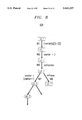
- FIG. 2 is a detail of a node in the state space generated by the verification system
- FIG. 3 is a detail of tables used in the verification system
- FIG. 4 is an example system which computes prime numbers according to the method of the sieve of Eratosthenes
- FIGS. 5A and 5B are a PROMELA description of the system of FIG. 4;
- FIGS. 6A-6F show the reduction in state space achievable in the system of FIG. 4 by using the technniques of the invention
- FIG. 7 shows how the state reduction technique reduces transitions from a node
- FIG. 8 is a detailed view of a portion of the state space of FIG. 6;
- FIG. 9 is an initialization algorithm for state reduction
- FIG. 10 is an algorithm for an expansion step
- FIG. 11 is an algorithm which implements the expansion step for the transitions in the Buechi automaton
- FIG. 12 is an extension of the algorithm for detecting cycles.
- FIG. 13 is an algorithm for performing a reduced expansion.
- FIG. 1 presents an overview of a verification system 101 which incorporates the invention.
- Verification system 101 takes as its inputs a system description 103 and a description of a required property 107 of the system of description 103.
- Description 103 describes the system being verified as a set of concurrently-operating asynchronous processes 105(0. . . n). The processes communicate with each other by means of synchronous and asynchronous message passing.
- system description 103 is written in PROMELA, described in detail in the Holzmann reference.
- Required property 107 and system description 103 are input to verifier generator 109, which then generates a verifier 111.
- Verifier generator 109 in the preferred embodiment is the SPIN model checker, which is described in detail in the Holzmann reference.
- verifier generator 109 The output of verifier generator 109 is a verifier program 111.
- verifier program 111 When verifier program 111 is executed, it verifies whether the system described in system description 103 has required property 107 by performing a reachability analysis on states of the system of description 103. In the course of performing the reachability analysis, verifier 111 constructs reduced state space 119 which contains state graph 125. State graph 125 consists of nodes 121 specifying states of the system described in system description 103 and edges 123 describing transitions between the states of the nodes 121. The result of the verification, indicating whether the system of description 103 has the required property 107 is output at result 117.
- FIG. 2 shows a detail of a node 121.
- Each node 121 has a global state portion 201 and a per-process state portion 203 for each process specified in system description 103.
- the global state portion includes the state of any global variables 205, i.e., variables which can be set and/or read by more than one process and the state of any global queues 207, i.e., queues which are shared between processes.
- Each per-process state portion 203 for a process 105(n) includes the state of any variables 209(n) local to the process, the state of the process's program counter 210(n), and the state of any queues 211(n) local to the process.
- state graph 125 may have an enormous number of nodes. For example, if the system of system description 103 has 3 processes and no global state, each process can have ten different combinations of values in per-process state 203, and the combinations may occur in any order, then the potential number of nodes in the system is (10*10*10) or 1000 nodes, and of course most systems will have more processes and/or more states.
- Verifier 111 includes a transition table 113 which is compiled from system description 103 and which lists all state transitions 123 which the system of system description 103 is capable of. Transition table 113 is shown in detail at FIG. 3. There is an entry TTE 203 for each state which is indexed by a transition number 201. Each entry describes an enabling condition (EC) 205 for the transition, for example a value of a variable or a state of a queue, and an action 207 to be taken on the transition.
- EC enabling condition
- Each entry in transition table 113 has a corresponding entry in tag table 115 which indicates the significance of the transition for state reduction.
- Each transition 123 belongs to one of three classes:
- the transitions in a node 121 are further bundled according to the processes 105 whose state is involved in the transitions. In a preferred embodiment, all of the transitions which change state belonging to a given process are bundled together. If the values in a node 121 permit one or more bundles of transitions 123 in which all of the the transitions are unconditionally safe, only the transitions in one of the bundles need be taken, and only the nodes 121 reached by those transitions need be included in reduced state space 119. If is a bundle in which all transitions are conditionally safe, the conditionally safe transitions can be treated as safe at run time. This is done by making run-time checks for the conditions of the safe transitions.
- the bundle of safe transitions can be treated in the same fashion as a bundle of unconditionally safe transitions. If there are no bundles of transitions which include only unconditionally safe transitions or conditionally safe transitions whose conditions are satisfied by the current state, then all of the transitions and their target nodes must be incorporated into graph 125.
- node 121(a) which has two bundles 709(a) and 709(b), each of which includes nothing but unconditionally safe transitions 703, a third bundle 711, which contains conditionally safe transitions 705, and a fourth bundle consisting of a single unsafe transition 707.
- node 121 (a)' remains with only bundle 709(a) of unconditionally safe transitions 703.
- node 121(b) which has a bundle 713 of two conditionally safe transitions 705(a) and 705(b) and another bundle 715 of transitions 707 which are unsafe.
- node 121(b)' has only the transitions in bundle 713.
- Node 121(c) has only bundles 721 and 723 which include unsafe transitions 707, and consequently, no state reduction is possible.
- the safeness class of a transition is indicated in tag table 115.
- tag table 115 As shown in FIG. 3, there is an entry 209 in tag table 115 corresponding to each transition in transition table 113.
- Tag 211 the contents of the entry, indicates whether the corresponding transition is unconditionally safe, conditionally safe, or unsafe. In the case of a conditionally safe transition, tag 211 is a code which indicates what kind of run-time check must be made.
- verifier 111 checks tag table 115 for each transition and puts the reduced number of transitions 123 and nodes 121 permitted by the safeness properties of the transitions in state graph 125.
- FIG. 4 shows how system 401 implements the algorithm.
- the system consists of five processes 403(0 . . . 4) plus a process (not shown) for providing the integers 2-12 in order.
- the prime numbers integers divisible only by themselves and 1) in that sequence of integers are 2,3,5,7, and 11.
- each process 403 receives integers from the process on the left; each process stores the first integer it receives; from then on, it discards any integer which is divisible by its stored integer and passes any integer which is not divisible to the right.
- process 403(0) stores the number in its local variable myval.
- the next number is 3. 3 is not divisible by 2, so as shown in the second row, process 403(0) passes 3 to process 403(1). This is the first value process 403(1) has received, so it stores the value in its local variable myval.
- the next number is 4. What happens with it is also shown in row 2. 4 is divisible by 2, so process 403(0) discards the value.
- FIGS. 5A and 5B show a PROMELA description 501 for system 401.
- the description has four major components: init 509, right 507, middle 505, and left 503.
- Components 503 through 507 represent processes in system 401; left 503 is the process which provides the integers in increasing order; it has a single channel which outputs a value to process 403(0).
- middle 505 represents the processes 403 which receive values from the left and discard them or pass them to the right; each of these processes has two channels, one to its neighbor on the left and one to its neighbor on the right.
- right 507 represents the rightmost process 403. It has a single channel to its neighbor on the left.
- init first creates and runs the process described by left 503; then init creates and runs processes described by middle 507 up to a maximum number established by a parameter N. In FIG. 4, these are the processes 403(0 . . . 3). Finally, it creates and runs the process described by right 507, process 403(4) in FIG. 4. In creating the processes 403, init sets up the channels for each process as described above.
- each middle process 403 stores the first value it receives. With each additional value, it divides the value by the stored value. If the division is even, the value is discarded; otherwise, it is passed to the right. As shown at 507, the right process simply stores the first value it receives and discards the rest.
- transitions involving sending and receiving are conditionally safe, but in system 401, the conditions are always satisfied, and these transitions, too, are always safe. Since all of the transitions are always safe, that is the case, the state space can be reduced to the number of states required for each process 403 in turn to receive its first value, divide the next value by the first value from the left, and do nothing if the result is 0 and otherwise send the next value.
- FIGS. 6A-6F show the results of the reduction.
- State space 601 is the states and transitions made by a version of system 401 which has three middle processes 403 and finds the primes through 5. States which remain in the reduced state space are shown as square nodes 605, while states which are not part of the reduced state space are shown as round nodes 603.
- FIG. 8 shows a detail of area 609 of FIG. 6.
- Each node 121 has been labelled with a name (s1-1, s2-1, etc.) and each transition 123 has been labelled to indicate what pan of the state of system 401 is affected by it.
- transitions 801-805 there is only one transition 123 per node, and consequently, no state reduction is possible.
- node s4 -- 1 there are two transitions 123.
- each of the transitions is a bundle consisting of one transition and only one of the bundles needs needs to be included in the state space.
- Verifier 111 choses the bundle containing transition 809, and nodes 121 reachable by transition 807 need not be included in reduced state space 119.
- the safeness class of the transition As described above, the only characteristic of a transition 123 which is taken into account in determining whether a bundle is unconditionally safe, conditionally safe, or unsafe is the safeness class of the transition. That is sufficient to verify some specific safety properties of the system of description 103, for example, that the system will not deadlock.
- three conditions must be met by all of the transitions in a bundle of transitions before the bundle is used to the exclusion of other bundles to generate reduced state space 119. The conditions may be described as follows:
- Condition C1 is a generalization of the requirement that all transitions in a bundle of transitions which are used to construct reduced state space 119 must be either unconditionally safe or conditionally safe.
- Condition C2 requires that no transition in the bundle return to a state 121 which is already in reduced state space 119 and which verifier 111 has not yet finished expanding, thereby forming a directed cycle in reduced state space 119.
- Condition C3 requires that one transition in the bundle may not alter a value which is mentioned in the property 107 being checked. All of these conditions are explored more rigorously in the following "Detailed Explanation".
- the following explanation first presents a theoretical justification for the technique and then presents details of the technique.
- the technique applies generally to any problem which can be formalized as a reachability analysis problem in a finite labeled transition system (LTS). This specifically includes the problems of proving safety, liveness, and linear time temporal logic properties for any finite state concurrent system.
- LTS finite labeled transition system
- An LTS is defined as a triple ⁇ S,s 0 ,T ⁇ , where S is a finite set of states, s 0 is a distinguished initial state in S, and T is a finite set of transitions, with T .OR right.(S ⁇ S).
- S is a finite set of states
- s 0 is a distinguished initial state in S
- T is a finite set of transitions, with T .OR right.(S ⁇ S).
- an LTS can be used to formalize the behavior of a single sequential process. It can also formalize the combined behavior of a finite number of interacting and asynchronously executing sequential processes. Each transition of the LTS then corresponds to the execution of a specific atomic statement within one of the processes, in accordance with a standard interleaving semantics of concurrency.
- the LTS can be represented by a graph with nodes corresponding to the states in S and directed edges corresponding to the transitions in T.
- a connected path through this graph then defines the effects of a possible execution in the underlying concurrent system. There will be at least one path through the graph for every possible way in which the execution of process statements could be interleaved in time.
- Cond( ⁇ ) is the subset of S where ⁇ is enabled (or ⁇ executable ⁇ [H92]), and
- Act( ⁇ ,s) is that state of S that is reached when ⁇ is executed in a given s ⁇ Cond( ⁇ ).
- a statement in a sequential process is ⁇ enabled ⁇ or ⁇ executable ⁇ only if it is pointed to by the current program counter of the sequential process that contains that statement.
- a message send operation for instance, can be defined to be enabled only if also the destination message buffer is non-full, and a message receive operation can be defined to be enabled when also the source message buffer is non-empty.
- Act(b,Act( ⁇ ,s)) Act( ⁇ ,Act(b,s)), i.e., the effect of executing ⁇ followed by b is indistinguishable from that of executing b followed by ⁇ .
- LTL linear-time temporal logic
- any next-time-free LTL formula can be formalized as a nondeterministic Buechi Automaton with a predefined initial state, and a finite set of acceptance states.
- the transitions in the Buechi Automaton carry predicate labels, each of which represents a boolean proposition.
- the boolean propositions can refer only to the (global) system-state of the labeled transition system for which the LTL formula formalizes a property.
- the Buechi Automaton itself can be represented by an LTS with predefined acceptance states.
- the satisfaction of an LTL formula can now be proven by detecting acceptance cycles in the synchronous product of two labeled transition systems: one representing the concurrent system and one representing the Buechi Automaton. The absence of acceptance cycles can similarly prove that the LTL formula cannot be satisfied.
- the synchronous product F ⁇ G of a labeled transition system F representing a concurrent system
- a Buechi Automaton G derived from a next-time-free LTL formula
- a statement ⁇ in F is said to be observable by Buechi Automaton G if there exists a label in G for which the corresponding proposition can have a different truth-value in at least one system-state s.di-elect cons.Cond( ⁇ ) and in Act( ⁇ ,s).
- the statement a can now be said to be
- the initialization 901 of the search is illustrated in FIG. 9.
- the optimization step can, as we shall argue, also include a precomputation of independence relations, with a static identification of all safe and conditionally safe process-statements.
- Two sets of states are then initialized with the predefined initial system state s 0 : the Statespace and the Stack.
- FIG. 10 first shows the expansion step for process statements, in routine dfs() (note: not the routine from line 5). In the absence of a Buechi Automaton, the calls on lines 5 and 16 could both be implemented as calls on dfs(N).
- the calls on lines 5 and 16 invoke the routine shown in FIG. 11, which implements the expansion step for the transitions in the Buechi Automaton.
- the state of the Buechi Automaton is part of compound system state s. Because the transitions in the Buechi Automaton represent boolean propositions from an underlying LTL formula, a transition t.di-elect cons.T G in B chi Automaton G will only be enabled if and only if proposition Label(t) holds.
- the synchronous coupling of system F and Buechi Automaton G is achieved by alternating the calls to Dfs(N), on line 16, and dfs(N) on line 28. Each pair of subsequent calls, explores one synchronous transition of F ⁇ G.
- FIG. 11 shows only the basic expansion step without the extra hooks that are required to detect the presence of acceptance cycles in the synchronous product of concurrent system and Buechi Automaton.
- Two separate values for parameter N serve to indicate in which part of the search the algorithm operates.
- To initiate the second search we include four extra lines between lines 28 and 29 of FIG. 11, as illustrated in FIG. 12. If the seed state is reachable from itself this can be detected and reported at line 24, as illustrated by lines 24a-d in FIG. 12.
- this critical step is performed on line 8a and is used to re-order the processes in such a way that processes that perform only (conditionally) safe transitions can be selected first for the expansion step on line 9. If the expansion succeeded (more about this below) we can ignore the (independent) transitions from all other processes by breaking out of the loop over processes on line 16f.
- the ordering step itself introduces virtually no runtime overhead. In the implementation discussed in Section 5, for instance, it is implemented by a table-lookup for unconditionally safe transitions, and by the evaluation of a precomputed boolean condition for conditionally safe transitions.
- An execution sequence ⁇ of an LTS can be defined either as a sequence of transitions or as the sequence of states that is traversed by these transitions.
- Eq( ⁇ ) be the set of all execution sequences that can be obtained from ⁇ by zero or more permutations of adjacent, globally independent, transitions.
- For each sequence in this set we can define the distance to ⁇ as the smallest number of permutations that must be performed to retrieve ⁇ . (This distance can be eithe finite or infinite.)
- Any sequence ⁇ that equals a finite prefix of at least one sequence in Eq( ⁇ ) is called a permuted prefix of ⁇ .
- PP'( ⁇ , ⁇ ) further be the subset of those sequences in PP( ⁇ , ⁇ ) that have the shortest distance to ⁇ . Note that the sequences in this set differ from ⁇ in at most a prefix of finite length. For each such sequence, therefore, we can define a finite prefix ⁇ ', such that the remainder of the sequence (after the deletion of ⁇ ') equals ⁇ .
- This prefix which can be longer than ⁇ , is called the minimal stable extension of ⁇ in ⁇ .
- a generalized permuted prefix ⁇ of an execution sequence ⁇ is finite execution sequence that can be transformed into a permuted prefix of ⁇ by omitting zero or more non-observable transitions.
- the reduced search algorithm generates at least one generalized permuted prefix ⁇ for every execution sequence ⁇ that can start from that state.
- Proof--The proof is by induction on the order in which states are removed from the depth-first stack in the reduced search algorithm.
- the set of enabled transitions in s does not contain a true subset of (conditionally) safe transitions that includes all the enabled transitions for one sequential process, and none of which leads to a successor state on the stack.
- the reduced search algorithm explores all enabled transitions from s and the Lemma holds by the same construction as was used in the proof of step [1.2].
- the set of enabled transitions in s does contain a true subset of (conditionally) safe transitions that includes all enabled transitions for one sequential process, and none of which leads to a successor state on the stack. Call that subset ⁇ , and call the (non-empty) set of all remaining transitions y.
- the reduced search algorithm explores only the sequences that start with a transition from ⁇ .
- any transition in ⁇ forms a generalized permuted prefix of length one for ⁇ . That is: each such transition either appears in ⁇ after a finite number of globally independent transitions, or it does not appear in ⁇ and is globally independent of all transitions that do appear.
- the sequence ⁇ . ⁇ ' is equal to a copy of ⁇ from which this first occurrence of b is deleted.
- the prefix ⁇ is then a generalized permuted prefix of the sequence ⁇ . ⁇ ' that starts at state s'.
- the prefix b. ⁇ must be a generalized permuted prefix of ⁇ , which starts at state s, which means that the Lemma also holds for this case. This completes the proof of the Lemma. ⁇
- the Lemma can be shown to imply that for every execution sequence ⁇ , the reduced search algorithm explores at least one execution sequence that becomes equivalent to ⁇ when a finite number of non-observable transitions are deleted from it. (This proof step is not detailed here.) Next we must show that this property is sufficient for the completeness of the search itself. To do this, we must take a closer look at the synchronous product of a concurrent system and a Buechi Automaton.
- the Lemma implies that the reduced search algorithm generates at least one M-equivalent sequence for each execution sequence of the concurrent system.
- the intuition for this is that all non-observable transitions correspond to stuttering steps. (This proof step is not further detailed here.)
- the correctness of the reduced search algorithm can now be formalized in the following theorem.
- the reduced search generates at least one M-equivalent sequence for each complete sequence that satisfies the LTL formula. All sequences that satisfy the LTL formula are detected in the non-reduced depth-first search as acceptance cycles in the synchronous product of the corresponding Buechi Automaton and the concurrent system (e.g., [W83][CVWY92][H92]). Therefore, if at least one M-equivalent sequence for such a satisfying sequence is generated in the reduced search, at least one acceptance cycle is necessarily detected. ⁇
- the statements of types (1)-(5) are conditionally safe if they do appear as guards in selection structures.
- the condition for the conditionally safe statements is defined as the logical and combination of the following clauses for each type of guard: (1) true (i.e., these statements contribute no additional constraints), (2) and (5) nempty(q), and (3) and (4) nfull(q). Note that statements of type (2-5) can only contribute constraints of two statically determined types.
- PROMELA allows the dynamic creation of a finite number of processes, it is not always possible to determine a priori which processes will be able to access which queues.
- Exclusive send and receive access in our implementation, is therefore entered into the PROMELA specification as a logical assertion, which can be checked at runtime.
- the Appendix shows an example of a complete PROMELA specification for a leader election protocol from [DKR82], with the exclusive send and receive assertions added. It can easily be shown that the validity of an assertion of this type can be proven by both the non-reduced and the reduced search, even when the reduction is based on an invalid assertion of this type. The intuition behind this is that the reduced search can only permute globally independent statements, it cannot prevent their execution alltogether.
- At least one send or receive operation that violates an exclusive access assertion will eventually be executed in the reduced search, though perhaps at a different place then in the non-reduced search.
- the reduced search is stopped on the detection of an acceptance cycle before the violation of an exclusive access assertion can be demonstrated. In that case, however, the search has already reached its goal: it has detected the existence of at least one error (i.e., an acceptance cycle). If the violation of an exclusive access assertion can be demonstrated first, our implementation also reports an error (i.e., an assertion violation), which in that case means that the reduction itself was invalid.
Abstract
Description
(6) s.di-elect cons.(Cond(α)∩Cond(b))→{α,b}.di-elect cons.Ind(s).
Claims (15)
Priority Applications (1)
| Application Number | Priority Date | Filing Date | Title |
|---|---|---|---|
| US08/667,350 US5615137A (en) | 1994-06-01 | 1996-06-21 | On-the-fly model checking with partial-order state space reduction |
Applications Claiming Priority (2)
| Application Number | Priority Date | Filing Date | Title |
|---|---|---|---|
| US25202894A | 1994-06-01 | 1994-06-01 | |
| US08/667,350 US5615137A (en) | 1994-06-01 | 1996-06-21 | On-the-fly model checking with partial-order state space reduction |
Related Parent Applications (1)
| Application Number | Title | Priority Date | Filing Date |
|---|---|---|---|
| US25202894A Continuation | 1994-06-01 | 1994-06-01 |
Publications (1)
| Publication Number | Publication Date |
|---|---|
| US5615137A true US5615137A (en) | 1997-03-25 |
Family
ID=22954316
Family Applications (1)
| Application Number | Title | Priority Date | Filing Date |
|---|---|---|---|
| US08/667,350 Expired - Lifetime US5615137A (en) | 1994-06-01 | 1996-06-21 | On-the-fly model checking with partial-order state space reduction |
Country Status (4)
| Country | Link |
|---|---|
| US (1) | US5615137A (en) |
| EP (1) | EP0685792A1 (en) |
| JP (1) | JPH07334566A (en) |
| CA (1) | CA2147536A1 (en) |
Cited By (39)
| Publication number | Priority date | Publication date | Assignee | Title |
|---|---|---|---|---|
| US5768498A (en) * | 1996-01-23 | 1998-06-16 | Lucent Technologies | Protocol verification using symbolic representations of queues |
| US6031983A (en) * | 1997-09-03 | 2000-02-29 | Sgs-Thomson Microelectronics Limited | Post image techniques |
| US6059837A (en) * | 1997-12-30 | 2000-05-09 | Synopsys, Inc. | Method and system for automata-based approach to state reachability of interacting extended finite state machines |
| US6099575A (en) * | 1998-06-23 | 2000-08-08 | Lucent Technologies Inc. | Constraint validity checking |
| US6106567A (en) * | 1998-04-28 | 2000-08-22 | Motorola Inc. | Circuit design verification tool and method therefor using maxwell's equations |
| US6178394B1 (en) * | 1996-12-09 | 2001-01-23 | Lucent Technologies Inc. | Protocol checking for concurrent systems |
| US6295515B1 (en) * | 1997-11-03 | 2001-09-25 | Lucent Technologies Inc. | Static partial order reduction |
| US20010037492A1 (en) * | 2000-03-16 | 2001-11-01 | Holzmann Gerard J. | Method and apparatus for automatically extracting verification models |
| US6339837B1 (en) | 1998-02-25 | 2002-01-15 | Zhe Li | Hybrid method for design verification |
| US6353896B1 (en) * | 1998-12-15 | 2002-03-05 | Lucent Technologies Inc. | Method and apparatus for testing event driven software |
| US20020100022A1 (en) * | 2000-05-08 | 2002-07-25 | Holzmann Gerard J. | Method and apparatus for automatic verification of properties of a concurrent software system |
| GB2377515A (en) * | 2001-07-09 | 2003-01-15 | Motorola Inc | Test Specifications for System Specifications |
| US6609230B1 (en) | 1999-02-24 | 2003-08-19 | Zhe Li | Method for design verification using modular templates of test benches |
| US20030158720A1 (en) * | 2001-08-24 | 2003-08-21 | Wayne Biao Liu | Space reduction in compositional state systems |
| US20030177472A1 (en) * | 2002-03-18 | 2003-09-18 | Sun Microsystems, Inc., A Delaware Corporation | Method and apparatus for deployment of high integrity software using reduced dynamic memory allocation |
| US20030177475A1 (en) * | 2002-03-18 | 2003-09-18 | Sun Microsystems, Inc., A Delaware Corporation | Method and apparatus for deployment of high integrity software using initialization order and calling order constraints |
| US20030177474A1 (en) * | 2002-03-18 | 2003-09-18 | Sun Microsystems, Inc., A Delaware Corporation | Method and apparatus for deployment of high integrity software using static procedure return addresses |
| US6651186B1 (en) | 2000-04-28 | 2003-11-18 | Sun Microsystems, Inc. | Remote incremental program verification using API definitions |
| US6654715B1 (en) * | 1998-12-17 | 2003-11-25 | Fujitsu Limited | Apparatus, method, and storage medium for verifying logical device |
| US20030225552A1 (en) * | 2002-05-30 | 2003-12-04 | Nec Corporation | Efficient approaches for bounded model checking |
| US20040003365A1 (en) * | 2002-06-27 | 2004-01-01 | Sun Microsystems, Inc. A Delaware Corporation | Method and apparatus for performing operation on physical design data |
| US6675338B1 (en) | 2000-08-09 | 2004-01-06 | Sun Microsystems, Inc. | Internally generated vectors for burnin system |
| US20040006454A1 (en) * | 2002-06-27 | 2004-01-08 | Sun Microsystem, Inc., Delaware Corporation | System and method for modeling digital systems having queue-like operating characteristics |
| US6691078B1 (en) * | 1999-07-29 | 2004-02-10 | International Business Machines Corporation | Target design model behavior explorer |
| US6816821B1 (en) | 1997-09-03 | 2004-11-09 | Stmicroelectronics Limited | Post image techniques |
| US20040261066A1 (en) * | 2003-06-18 | 2004-12-23 | Microsoft Corporation | Declarative state space reduction in a transactional messaging language |
| US20050010907A1 (en) * | 2003-07-07 | 2005-01-13 | Namjoshi Kedar Sharadchandra | Method and apparatus for reducing a program size while maintaining branching time properties and automated checking of such reduced programs |
| US6880155B2 (en) | 1999-02-02 | 2005-04-12 | Sun Microsystems, Inc. | Token-based linking |
| US6883163B1 (en) | 2000-04-28 | 2005-04-19 | Sun Microsystems, Inc. | Populating resource-constrained devices with content verified using API definitions |
| US20050086648A1 (en) * | 2003-10-15 | 2005-04-21 | Microsoft Corporation | Object-based systematic state space exploration of software |
| WO2005106649A2 (en) * | 2004-05-05 | 2005-11-10 | Silverdata Limited | An analytical software design system |
| US6981245B1 (en) | 2000-09-14 | 2005-12-27 | Sun Microsystems, Inc. | Populating binary compatible resource-constrained devices with content verified using API definitions |
| US6986132B1 (en) | 2000-04-28 | 2006-01-10 | Sun Microsytems, Inc. | Remote incremental program binary compatibility verification using API definitions |
| US20060218534A1 (en) * | 2005-03-28 | 2006-09-28 | Nec Laboratories America, Inc. | Model Checking of Multi Threaded Software |
| US7158993B1 (en) | 1999-11-12 | 2007-01-02 | Sun Microsystems, Inc. | API representation enabling submerged hierarchy |
| US7181725B1 (en) * | 1998-06-26 | 2007-02-20 | Deutsche Telekom Ag | Method for verifying safety properties of java byte code programs |
| US20090178044A1 (en) * | 2008-01-09 | 2009-07-09 | Microsoft Corporation | Fair stateless model checking |
| US20110296424A1 (en) * | 2010-05-28 | 2011-12-01 | International Business Machines Corporation | Synthesis of Memory Barriers |
| US20170116764A1 (en) * | 2015-10-23 | 2017-04-27 | International Business Machines Corporation | Dynamic interaction graphs with probabilistic edge decay |
Families Citing this family (6)
| Publication number | Priority date | Publication date | Assignee | Title |
|---|---|---|---|---|
| ES2177871T3 (en) * | 1996-09-05 | 2002-12-16 | Siemens Ag | PROCEDURE FOR THE VERIFICATION OF A PROGRAM, WHICH IS PRESENT IN A LANGUAGE FOR PROGRAMMABLE MEMORY CONTROLS, THROUGH A COMPUTER. |
| WO1998040796A1 (en) * | 1997-03-11 | 1998-09-17 | Siemens Aktiengesellschaft | Method for computer-assisted error checking of sensors and/or actors in technical systems |
| US6408262B1 (en) * | 1998-03-27 | 2002-06-18 | Iar Systems A/S | Method and an apparatus for analyzing a state based system model |
| US6374368B1 (en) | 1999-05-21 | 2002-04-16 | Microsoft Corporation | Weakest precondition analysis |
| US7644396B2 (en) | 2005-11-29 | 2010-01-05 | Microsoft Corporation | Optimal program execution replay and breakpoints |
| EP2069911A4 (en) * | 2006-10-05 | 2011-01-19 | Nec Lab America Inc | Inter-procedural dataflow analysis of parameterized concurrent software |
Family Cites Families (1)
| Publication number | Priority date | Publication date | Assignee | Title |
|---|---|---|---|---|
| US5297150A (en) * | 1992-06-17 | 1994-03-22 | International Business Machines Corporation | Rule-based method for testing of programming segments |
-
1995
- 1995-04-21 CA CA002147536A patent/CA2147536A1/en not_active Abandoned
- 1995-05-24 EP EP95303490A patent/EP0685792A1/en not_active Withdrawn
- 1995-06-01 JP JP7134610A patent/JPH07334566A/en not_active Withdrawn
-
1996
- 1996-06-21 US US08/667,350 patent/US5615137A/en not_active Expired - Lifetime
Non-Patent Citations (20)
| Title |
|---|
| "A Partial Order Approach to Branch Time Logic Model Checking", by Gerth et al., IEEE, Israel Symposium on the Theory of Computing and Systems, 1994, pp. 130-139. |
| "Petri Net Approach to Correctness Checking on Changing Software", Research Disclosure, No. 348, Apr. 1993, Havant GB, p. 225. |
| "Protocol Design: Redefining the State of the Art", by G. Holzmann, IEEE Software, vol. 9, Issue 1, Jan. 1992, pp. 17-22. |
| "The Existence of Refinement Mappings", by M. Abadi et al., IEEE Logic in Computer Science, 3rd Annual Symposium, 1988, pp. 165-175. |
| A Partial Order Approach to Branch Time Logic Model Checking , by Gerth et al., IEEE, Israel Symposium on the Theory of Computing and Systems, 1994, pp. 130 139. * |
| A. Valmari, "A Stubborn Attack on State Explosion", Formal Methods in System Design, vol. 1, No. 4, pp. 297-322, 1990. |
| A. Valmari, "On-The-Fly Verification with Stubborn Sets", 5th Int'l Conf. on Computer Aided Verification, Greece, 1993, Lecture Notes in Comp. Science, Springer-Verlag, 397-408. |
| A. Valmari, A Stubborn Attack on State Explosion , Formal Methods in System Design , vol. 1, No. 4, pp. 297 322, 1990. * |
| A. Valmari, On The Fly Verification with Stubborn Sets , 5th Int l Conf. on Computer Aided Verification, Greece, 1993, Lecture Notes in Comp. Science, Springer Verlag, 397 408. * |
| P. Godefroid, "Using Partial Orders to Improve Automatic Verification Methods", DIMACS Serial in Discrete Mathematics and Theoretical Computer Science, vol. 3, 1991. |
| P. Godefroid, P. Wolper, "Using Partial Orders for the Efficient Verification of Deadlock Freedom and Safety Properties", Formula Methods in Systems Design, Kluwer Academic Publishers, vol. 2, No. 2, pp. 149-164, Apr. 1993. |
| P. Godefroid, P. Wolper, Using Partial Orders for the Efficient Verification of Deadlock Freedom and Safety Properties , Formula Methods in Systems Design , Kluwer Academic Publishers, vol. 2, No. 2, pp. 149 164, Apr. 1993. * |
| P. Godefroid, Using Partial Orders to Improve Automatic Verification Methods , DIMACS Serial in Discrete Mathematics and Theoretical Computer Science, vol. 3, 1991. * |
| Petri Net Approach to Correctness Checking on Changing Software , Research Disclosure, No. 348, Apr. 1993, Havant GB, p. 225. * |
| Protocol Design: Redefining the State of the Art , by G. Holzmann, IEEE Software, vol. 9, Issue 1, Jan. 1992, pp. 17 22. * |
| R. Gopal, "Dynamic Program Slicing Based on Dependence Relations", Proceedings of the Conference on Software Maintenance 1991, Oct. 17, 1991, pp. 191-200. |
| R. Gopal, Dynamic Program Slicing Based on Dependence Relations , Proceedings of the Conference on Software Maintenance 1991, Oct. 17, 1991, pp. 191 200. * |
| S. Katz, D. Peled, "Verification of Distributed Programs Using Representative Interleaving Sequences", Distributed Computing, vol. 6, pp. 107-120 (1992). |
| S. Katz, D. Peled, Verification of Distributed Programs Using Representative Interleaving Sequences , Distributed Computing , vol. 6, pp. 107 120 (1992). * |
| The Existence of Refinement Mappings , by M. Abadi et al., IEEE Logic in Computer Science, 3rd Annual Symposium, 1988, pp. 165 175. * |
Cited By (60)
| Publication number | Priority date | Publication date | Assignee | Title |
|---|---|---|---|---|
| US5768498A (en) * | 1996-01-23 | 1998-06-16 | Lucent Technologies | Protocol verification using symbolic representations of queues |
| US6178394B1 (en) * | 1996-12-09 | 2001-01-23 | Lucent Technologies Inc. | Protocol checking for concurrent systems |
| US6031983A (en) * | 1997-09-03 | 2000-02-29 | Sgs-Thomson Microelectronics Limited | Post image techniques |
| US6816821B1 (en) | 1997-09-03 | 2004-11-09 | Stmicroelectronics Limited | Post image techniques |
| US6295515B1 (en) * | 1997-11-03 | 2001-09-25 | Lucent Technologies Inc. | Static partial order reduction |
| US6059837A (en) * | 1997-12-30 | 2000-05-09 | Synopsys, Inc. | Method and system for automata-based approach to state reachability of interacting extended finite state machines |
| US6339837B1 (en) | 1998-02-25 | 2002-01-15 | Zhe Li | Hybrid method for design verification |
| US6106567A (en) * | 1998-04-28 | 2000-08-22 | Motorola Inc. | Circuit design verification tool and method therefor using maxwell's equations |
| US6099575A (en) * | 1998-06-23 | 2000-08-08 | Lucent Technologies Inc. | Constraint validity checking |
| US7181725B1 (en) * | 1998-06-26 | 2007-02-20 | Deutsche Telekom Ag | Method for verifying safety properties of java byte code programs |
| US6353896B1 (en) * | 1998-12-15 | 2002-03-05 | Lucent Technologies Inc. | Method and apparatus for testing event driven software |
| US6654715B1 (en) * | 1998-12-17 | 2003-11-25 | Fujitsu Limited | Apparatus, method, and storage medium for verifying logical device |
| US20050097550A1 (en) * | 1999-02-02 | 2005-05-05 | Sun Microsystems, Inc. | Token-based linking |
| US6880155B2 (en) | 1999-02-02 | 2005-04-12 | Sun Microsystems, Inc. | Token-based linking |
| US7444631B2 (en) | 1999-02-02 | 2008-10-28 | Sun Microsystems, Inc. | Token-based linking |
| US6609230B1 (en) | 1999-02-24 | 2003-08-19 | Zhe Li | Method for design verification using modular templates of test benches |
| US6691078B1 (en) * | 1999-07-29 | 2004-02-10 | International Business Machines Corporation | Target design model behavior explorer |
| US7158993B1 (en) | 1999-11-12 | 2007-01-02 | Sun Microsystems, Inc. | API representation enabling submerged hierarchy |
| US20010037492A1 (en) * | 2000-03-16 | 2001-11-01 | Holzmann Gerard J. | Method and apparatus for automatically extracting verification models |
| US6651186B1 (en) | 2000-04-28 | 2003-11-18 | Sun Microsystems, Inc. | Remote incremental program verification using API definitions |
| US7231635B2 (en) | 2000-04-28 | 2007-06-12 | Sun Microsystems, Inc. | Remote incremental program verification using API definitions |
| US20040153827A1 (en) * | 2000-04-28 | 2004-08-05 | Sun Microsystems, Inc., A Delaware Corporation | Remote incremental program verification using API definitions |
| US6986132B1 (en) | 2000-04-28 | 2006-01-10 | Sun Microsytems, Inc. | Remote incremental program binary compatibility verification using API definitions |
| US6883163B1 (en) | 2000-04-28 | 2005-04-19 | Sun Microsystems, Inc. | Populating resource-constrained devices with content verified using API definitions |
| US20020100022A1 (en) * | 2000-05-08 | 2002-07-25 | Holzmann Gerard J. | Method and apparatus for automatic verification of properties of a concurrent software system |
| US6675338B1 (en) | 2000-08-09 | 2004-01-06 | Sun Microsystems, Inc. | Internally generated vectors for burnin system |
| US6981245B1 (en) | 2000-09-14 | 2005-12-27 | Sun Microsystems, Inc. | Populating binary compatible resource-constrained devices with content verified using API definitions |
| GB2377515A (en) * | 2001-07-09 | 2003-01-15 | Motorola Inc | Test Specifications for System Specifications |
| US7076407B2 (en) * | 2001-08-24 | 2006-07-11 | Wayne Biao Liu | Space reduction in compositional state systems |
| US20030158720A1 (en) * | 2001-08-24 | 2003-08-21 | Wayne Biao Liu | Space reduction in compositional state systems |
| US20030177475A1 (en) * | 2002-03-18 | 2003-09-18 | Sun Microsystems, Inc., A Delaware Corporation | Method and apparatus for deployment of high integrity software using initialization order and calling order constraints |
| US20030177472A1 (en) * | 2002-03-18 | 2003-09-18 | Sun Microsystems, Inc., A Delaware Corporation | Method and apparatus for deployment of high integrity software using reduced dynamic memory allocation |
| US6996802B2 (en) | 2002-03-18 | 2006-02-07 | Sun Microsystems, Inc. | Method and apparatus for deployment of high integrity software using initialization order and calling order constraints |
| US7010783B2 (en) | 2002-03-18 | 2006-03-07 | Sun Microsystems, Inc. | Method and apparatus for deployment of high integrity software using reduced dynamic memory allocation |
| US20030177474A1 (en) * | 2002-03-18 | 2003-09-18 | Sun Microsystems, Inc., A Delaware Corporation | Method and apparatus for deployment of high integrity software using static procedure return addresses |
| US7181737B2 (en) | 2002-03-18 | 2007-02-20 | Sun Microsystems, Inc. | Method and apparatus for deployment of high integrity software using static procedure return addresses |
| US20030225552A1 (en) * | 2002-05-30 | 2003-12-04 | Nec Corporation | Efficient approaches for bounded model checking |
| US7711525B2 (en) * | 2002-05-30 | 2010-05-04 | Nec Corporation | Efficient approaches for bounded model checking |
| US6912705B2 (en) | 2002-06-27 | 2005-06-28 | Sun Microsystems, Inc. | Method and apparatus for performing operation on physical design data |
| US20040006454A1 (en) * | 2002-06-27 | 2004-01-08 | Sun Microsystem, Inc., Delaware Corporation | System and method for modeling digital systems having queue-like operating characteristics |
| US20040003365A1 (en) * | 2002-06-27 | 2004-01-01 | Sun Microsystems, Inc. A Delaware Corporation | Method and apparatus for performing operation on physical design data |
| US20040261066A1 (en) * | 2003-06-18 | 2004-12-23 | Microsoft Corporation | Declarative state space reduction in a transactional messaging language |
| US7343589B2 (en) * | 2003-06-18 | 2008-03-11 | Microsoft Corporation | Declarative state space reduction in a transactional messaging language |
| US20050010907A1 (en) * | 2003-07-07 | 2005-01-13 | Namjoshi Kedar Sharadchandra | Method and apparatus for reducing a program size while maintaining branching time properties and automated checking of such reduced programs |
| US7526750B2 (en) * | 2003-10-15 | 2009-04-28 | Microsoft Corporation | Object-based systematic state space exploration of software |
| US20050086648A1 (en) * | 2003-10-15 | 2005-04-21 | Microsoft Corporation | Object-based systematic state space exploration of software |
| WO2005106649A3 (en) * | 2004-05-05 | 2006-03-23 | Silverdata Ltd | An analytical software design system |
| US8370798B2 (en) | 2004-05-05 | 2013-02-05 | Silverdata Limited | Analytical software design system |
| US8943465B2 (en) | 2004-05-05 | 2015-01-27 | Verum Holding B.V. | Analytical software design system |
| US20080263506A1 (en) * | 2004-05-05 | 2008-10-23 | Silverdata Limited | Analytical Software Design System |
| WO2005106649A2 (en) * | 2004-05-05 | 2005-11-10 | Silverdata Limited | An analytical software design system |
| US8266600B2 (en) | 2005-03-28 | 2012-09-11 | Nec Laboratories America, Inc. | Model checking of multi threaded software |
| US20060218534A1 (en) * | 2005-03-28 | 2006-09-28 | Nec Laboratories America, Inc. | Model Checking of Multi Threaded Software |
| US20090178044A1 (en) * | 2008-01-09 | 2009-07-09 | Microsoft Corporation | Fair stateless model checking |
| US9063778B2 (en) | 2008-01-09 | 2015-06-23 | Microsoft Technology Licensing, Llc | Fair stateless model checking |
| US20110296424A1 (en) * | 2010-05-28 | 2011-12-01 | International Business Machines Corporation | Synthesis of Memory Barriers |
| US8839248B2 (en) * | 2010-05-28 | 2014-09-16 | International Business Machines Corporation | Synthesis of memory barriers |
| US20170116764A1 (en) * | 2015-10-23 | 2017-04-27 | International Business Machines Corporation | Dynamic interaction graphs with probabilistic edge decay |
| US10013782B2 (en) * | 2015-10-23 | 2018-07-03 | International Business Machines Corporation | Dynamic interaction graphs with probabilistic edge decay |
| US10249070B2 (en) | 2015-10-23 | 2019-04-02 | International Business Machines Corporation | Dynamic interaction graphs with probabilistic edge decay |
Also Published As
| Publication number | Publication date |
|---|---|
| CA2147536A1 (en) | 1995-12-02 |
| JPH07334566A (en) | 1995-12-22 |
| EP0685792A1 (en) | 1995-12-06 |
Similar Documents
| Publication | Publication Date | Title |
|---|---|---|
| US5615137A (en) | On-the-fly model checking with partial-order state space reduction | |
| Holzmann et al. | An improvement in formal verification | |
| Edelkamp et al. | Directed explicit model checking with HSF-SPIN | |
| Godefroid | Software model checking: The VeriSoft approach | |
| Wolper et al. | Partial-order methods for temporal verification | |
| Hong et al. | A test sequence selection method for statecharts | |
| Kupferman et al. | Vacuity detection in temporal model checking | |
| Chechik et al. | Model-checking over multi-valued logics | |
| Holzmann | Automated protocol validation in argos: Assertion proving and scatter searching | |
| Benedikt et al. | Model checking of unrestricted hierarchical state machines | |
| US6499132B1 (en) | System and method for analyzing temporal expressions | |
| Hojati et al. | BDD-based debugging of designs using language containment and fair CTL | |
| Holzmann | Explicit-state model checking | |
| Attie et al. | Synthesis of concurrent programs for an atomic read/write model of computation | |
| Bozga et al. | State space reduction based on live variables analysis | |
| Godefroid | Exploiting symmetry when model-checking software | |
| Janowska et al. | Slicing of timed automata with discrete data | |
| Du et al. | Local model checking and protocol analysis | |
| Peled et al. | Relaxed visibility enhances partial order reduction | |
| Gallardo et al. | A framework for automatic construction of abstract promela models | |
| Garg | Observation of Global Properties in Distributed Systems. | |
| Dobrikov et al. | Optimising the ProB model checker for B using partial order reduction | |
| Dwyer et al. | Flow analysis for verifying specifications of concurrent and distributed software | |
| Schoot et al. | An improvement of partial‐order verification | |
| Yoneda et al. | On model checking for Petri nets and a linear-time temporal logic |
Legal Events
| Date | Code | Title | Description |
|---|---|---|---|
| AS | Assignment |
Owner name: LUCENT TECHNOLOGIES INC., NEW JERSEY Free format text: ASSIGNMENT OF ASSIGNORS INTEREST;ASSIGNOR:AT&T CORP.;REEL/FRAME:008196/0181 Effective date: 19960329 |
|
| STCF | Information on status: patent grant |
Free format text: PATENTED CASE |
|
| FEPP | Fee payment procedure |
Free format text: PAYOR NUMBER ASSIGNED (ORIGINAL EVENT CODE: ASPN); ENTITY STATUS OF PATENT OWNER: LARGE ENTITY |
|
| FPAY | Fee payment |
Year of fee payment: 4 |
|
| AS | Assignment |
Owner name: THE CHASE MANHATTAN BANK, AS COLLATERAL AGENT, TEX Free format text: CONDITIONAL ASSIGNMENT OF AND SECURITY INTEREST IN PATENT RIGHTS;ASSIGNOR:LUCENT TECHNOLOGIES INC. (DE CORPORATION);REEL/FRAME:011722/0048 Effective date: 20010222 |
|
| FPAY | Fee payment |
Year of fee payment: 8 |
|
| AS | Assignment |
Owner name: LUCENT TECHNOLOGIES INC., NEW JERSEY Free format text: TERMINATION AND RELEASE OF SECURITY INTEREST IN PATENT RIGHTS;ASSIGNOR:JPMORGAN CHASE BANK, N.A. (FORMERLY KNOWN AS THE CHASE MANHATTAN BANK), AS ADMINISTRATIVE AGENT;REEL/FRAME:018584/0446 Effective date: 20061130 |
|
| FPAY | Fee payment |
Year of fee payment: 12 |