US5607015A - Method and apparatus for installing acoustic sensors in a wellbore - Google Patents
Method and apparatus for installing acoustic sensors in a wellbore Download PDFInfo
- Publication number
- US5607015A US5607015A US08/504,875 US50487595A US5607015A US 5607015 A US5607015 A US 5607015A US 50487595 A US50487595 A US 50487595A US 5607015 A US5607015 A US 5607015A
- Authority
- US
- United States
- Prior art keywords
- cable
- load
- transmission cable
- hanger
- sensors
- Prior art date
- Legal status (The legal status is an assumption and is not a legal conclusion. Google has not performed a legal analysis and makes no representation as to the accuracy of the status listed.)
- Expired - Lifetime
Links
- 238000000034 method Methods 0.000 title claims abstract description 16
- 230000005540 biological transmission Effects 0.000 claims abstract description 52
- 230000015572 biosynthetic process Effects 0.000 description 22
- 238000005755 formation reaction Methods 0.000 description 22
- 238000002347 injection Methods 0.000 description 14
- 239000007924 injection Substances 0.000 description 14
- 239000002699 waste material Substances 0.000 description 13
- 208000010392 Bone Fractures Diseases 0.000 description 11
- 239000012530 fluid Substances 0.000 description 7
- 238000012544 monitoring process Methods 0.000 description 7
- 210000002445 nipple Anatomy 0.000 description 4
- 238000003491 array Methods 0.000 description 3
- 238000009434 installation Methods 0.000 description 3
- 239000002002 slurry Substances 0.000 description 3
- 238000013459 approach Methods 0.000 description 2
- 239000004568 cement Substances 0.000 description 2
- 238000005520 cutting process Methods 0.000 description 2
- 238000005553 drilling Methods 0.000 description 2
- 239000000463 material Substances 0.000 description 2
- 238000012545 processing Methods 0.000 description 2
- 229910001369 Brass Inorganic materials 0.000 description 1
- 230000009286 beneficial effect Effects 0.000 description 1
- 239000010951 brass Substances 0.000 description 1
- 238000004364 calculation method Methods 0.000 description 1
- 238000004891 communication Methods 0.000 description 1
- 239000004020 conductor Substances 0.000 description 1
- 238000010276 construction Methods 0.000 description 1
- 230000000694 effects Effects 0.000 description 1
- 229920001971 elastomer Polymers 0.000 description 1
- 239000011440 grout Substances 0.000 description 1
- 239000013056 hazardous product Substances 0.000 description 1
- 238000003384 imaging method Methods 0.000 description 1
- 238000004519 manufacturing process Methods 0.000 description 1
- 238000013507 mapping Methods 0.000 description 1
- 238000013178 mathematical model Methods 0.000 description 1
- QSHDDOUJBYECFT-UHFFFAOYSA-N mercury Chemical compound [Hg] QSHDDOUJBYECFT-UHFFFAOYSA-N 0.000 description 1
- 229910052753 mercury Inorganic materials 0.000 description 1
- 239000002184 metal Substances 0.000 description 1
- 229910052751 metal Inorganic materials 0.000 description 1
- 238000005065 mining Methods 0.000 description 1
- 229920002635 polyurethane Polymers 0.000 description 1
- 239000004814 polyurethane Substances 0.000 description 1
- 239000011435 rock Substances 0.000 description 1
- 230000035939 shock Effects 0.000 description 1
- 239000002910 solid waste Substances 0.000 description 1
- 239000000243 solution Substances 0.000 description 1
- 229910001220 stainless steel Inorganic materials 0.000 description 1
- 239000010935 stainless steel Substances 0.000 description 1
- 238000012546 transfer Methods 0.000 description 1
- XLYOFNOQVPJJNP-UHFFFAOYSA-N water Substances O XLYOFNOQVPJJNP-UHFFFAOYSA-N 0.000 description 1
Images


Classifications
-
- E—FIXED CONSTRUCTIONS
- E21—EARTH OR ROCK DRILLING; MINING
- E21B—EARTH OR ROCK DRILLING; OBTAINING OIL, GAS, WATER, SOLUBLE OR MELTABLE MATERIALS OR A SLURRY OF MINERALS FROM WELLS
- E21B47/00—Survey of boreholes or wells
- E21B47/01—Devices for supporting measuring instruments on drill bits, pipes, rods or wirelines; Protecting measuring instruments in boreholes against heat, shock, pressure or the like
- E21B47/017—Protecting measuring instruments
Definitions
- the present invention relates to a method and apparatus for installing an array of sensors in a wellbore and in one of its aspects relates to a method and apparatus for installing an array of acoustic-energy sensors which are coupled into and are suspended on a transmission cable without subjecting the cable to undue tensile forces by connecting the transmission cable to a separate, load bearing cable at spaced intervals.
- waste materials e.g. drill cuttings or the like from well drilling operations
- the waste slurry may act as a fracturing fluid to form a fracture in the formation where the solid wastes from the slurry are deposited.
- wastes include any hazardous material
- the ecological effect that the disposed material may have on the environment is the ecological effect that the disposed material may have on the environment. That is, the wastes, once deposited in a formation, should not leach or migrate out of that formation into another formation, e.g. an aquifier, from which fluids, e.g. water, may be later produced to the surface. Therefore, the formations which are to be used as disposal zones need to be carefully selected.
- any hydraulic fracture(s) as it is being formed to prevent the fracture from extending (a) beyond the disposal zone into the surrounding formations or (b) into a fault within the zone whereby the waste material might flow from the fracture and through the fault into the surrounding formations.
- monitoring may be required by governmental agencies in the near future as more subterranean formations are used as waste disposal zones.
- acoustical-energy sensors e.g. geophones, hydrophones, etc.
- the sensors convert this acoustic-energy to signals which, in turn, are transmitted to the surface for processing to thereby develop the profile of the fracture(s) as it is being formed in the disposal zone.
- the sensor arrays may be positioned within either the well used for injecting the fracturing fluid (i.e. injection well) and/or in separate, spaced monitor wells (see copending and commonly-assigned U.S. patent application Ser. No. 08/196,621filed Feb. 14, 1994) or they may be placed within the well annulus of the injection or monitoring well (see co-pending and commonly assigned U.S. patent applications Ser. Nos. 08/426,306, filed Apr. 21, 1995, now U.S. Pat. No. 5,503,225, issued Apr. 2, 1996 and 08/435,015, filed May 5, 1995, now U.S. Pat. No. 5,524,709, issued Jun. 11, 1996.
- the sensor array may be attached to and lowered with a string of tubing whereby the weight of the tubing causes the array to contact the casing or the well annulus around the array can be filled with cement after the array is in position.
- tubing to install the array requires the use of a drilling rig or the like which adds significantly to the installation costs (e.g. may run as high as an additional 0.5 to 1 million dollars per installation).
- the weight of the array will normally require that the transmission cable include an additional load-bearing element (i.e. wire rope or the like) throughout its length to prevent the tensile forces developed in the cable from damaging or destroying the cable as the array is being installed.
- an additional load-bearing element i.e. wire rope or the like
- Such a specially-constructed transmission cable would significantly increase the deployment costs and manufacturing time for a typical array.
- the present invention provides a method and apparatus for installing an array of sensors in a wellbore wherein the sensors are incorporated into the lower end of a transmission cable which is required to communicate with the array once disposed within the wellbore.
- a load-bearing cable is simultaneously run into the wellbore side-by-side with the transmission cable and the two cables are clamped together at spaced intervals whereby a substantial portion of the tensile forces in the transmission cable is transferred to and is borne by the load-bearing cable thereby preventing damage to the transmission cable that may otherwise be caused by the tensile forces therein.
- the present method is useful in installing an array of sensors in any wellbore where such sensors may find application.
- an array of acoustic-energy sensors e.g. hydrophones, geophones, accelerometers, tiltmeters, etc.
- a standard transmission cable which can then be stored on a first reel until it is to be installed by paying out the cable over a first sheave into the wellbore.
- a load-bearing cable e.g. standard perforating cable
- the cables are connected together at spaced intervals to thereby transfer a substantial portion of the tensile force in the transmission cable to the load-bearing cable.
- each clamp is comprised of two elongated sections which define two axially-extending passages when the sections are aligned with each other for receiving the transmission cable and the load-bearing cable, respectively.
- the sections of a clamp are held together by metal bands or the like.
- the upper end of the load-bearing cable is secured to a cable hanger which, in turn, is also made in two symmetrical sections so that it can be assembled around the cables.
- the transmission cable passes through the hanger while the upper end of the load-bearing cable is secured thereto.
- the sections of the hanger are secured together and the hanger is then lowered onto a seat in the wellhead structure and may be releasably held in place by bolts of the like or it can be landed in a nipple or the like at the wellhead.
- the array and cables are easily removable from the well by merely releasing the bolts and removing hanger from the wellhead structure. Both cables can then be reeled in simultaneously, either onto individual reels as the clamps are removed or as a unit, if desired.
- FIG. 1 is an elevational view, partly in section, illustrating a typical injection well for disposing of waste materials into a subterranean formation wherein a sensor array has been installed in accordance with the present invention
- FIG. 2 is an enlarged view of the wellhead structure of FIG. 1, partly in section, further illustrating the present invention
- FIG. 2A is an enlarged view of another embodiment of the wellhead structure of FIG. 1, partly in section;
- FIG. 3 is a schematical view of the respective cables used in carrying out the present invention as they are being installed in a wellbore;
- FIG. 4 is an enlarged perspective view of a clamp which may be used to secure the two cables of the present invention together at spaced intervals along their lengths;
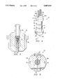
- FIG. 5 is an enlarged sectional view of the cable hanger structure of FIG. 1;
- FIG. 6 is a sectional view of the cable hanger structure taken along line 6--6 of FIG. 5.
- FIG. 1 discloses a typical well 10 which may be used for disposing of waste material into a subterranean formation 12. While well 10 is illustrated as an injection well (i.e. the well through which the wastes are to be injected), it should be understood that the present invention is equally useful in installing sensor arrays in monitor wells (not shown) which are normally spaced from the injection well or in any other wells when a sensor array may find application.
- injection well i.e. the well through which the wastes are to be injected
- monitor wells not shown
- disposal zone 12 will lie in a formation which is separated from overlying aquifiers 16 or the like by a layer of a relatively impermeable formation 17 (e.g. shale) which will aid in keeping any hydraulically-induced fractures within zone 12.
- waste materials e.g. oily solutions, drill cuttings, etc.
- Injection well 10 has a well casing 13 which extends from wellhead 14 at the surface through disposal zone 12 and has perforations 15 adjacent the disposal zone.
- casing 13 may be terminated above zone 12 with the rest of the wellbore being completed "open hole” or the like).
- a string of tubing 18 is positioned into the wellbore of injection well 10 and terminates near or at perforations 15 in casing 12.
- tubing 18 is not critical to the present invention in that, other than injection wells, a string of tubing may or may not be present when carrying out the present invention.
- Tubing 18 carries a packer 19 which isolates the injection zone 21 from the well annulus 20 which, in turn, is formed between casing 13 and tubing 18 above packer 19.
- an array of acoustic-energy sensors 22 is physically and electronically coupled into a standard transmission cable 23 and is to lowered thereon into a wellbore and is positioned to receive acoustical energy as it is generated by the fracturing of the disposal zone.
- the intervals at which the sensors will be spaced e.g. 15-200 feet
- a particular array may extend for a substantial distance (e.g. thousands of feet) above and/or below perforations 15 when positioned in an injection well.
- the array is to be positioned above the perforations 15 in injection well 10 (array not shown), it is preferably positioned within annulus 20 above packer 19.
- an array having a large number of sensors may have sensors which lie above, through, and below the expected vertical boundaries of the hydraulic fracture which is to be formed in zone 12.
- the number and spacing of the sensors along the transmission cable and their placement in a well will depend upon the particular application involved and is not critical to the present invention since the actual installation of a sensor array within its respective wellbore in accordance with the present invention will be substantially the same in all applications.
- the array of acoustical-energy sensors 22 (e.g. 26 geophones at 200 feet intervals) is made up into the lower end of transmission cable 23.
- cable 23 is selected from standard transmission cable of the type normally used on the surface in routine seismic operations (e.g. 0.62", integral 170 conductor cable, available from Mercury Cable.
- the cable can then be reeled onto a first spool 30 (FIG. 3) so that the array is positioned to come off first.
- Spool 30 is positioned near wellhead 14 and the lower end of transmission line 23 is passed over a sheave 31 which is substantially aligned with well 10 or tubing 18, as the case may be.
- Wellhead structure 14 is positioned on casing 13 and is comprised of housing 24 (e.g. spool piece) and a line wiper assembly 25.
- Line wipe r assembly 25 may be any of several which are commercially available but preferably is one which can be assembled onto housing 24 before the array is run into the wellbore, e.g. a single cable packoff head such as Hydraulic Line Wiper, Model B, Bowen Tools, Inc., Houston, Tex. which has removable internal elements (i.e. rubber and brass wiper unit) to thereby provide a large open bore therethrough.
- load-bearing cable 26 is simultaneously fed into the wellbore side-by-side with transmission cable 23.
- Load-bearing cable 26 may be selected from any cable (e.g. wire line) which is capable of withstanding the tensile forces developed in the transmission cable as it and the sensor array is lowered to its ultimate position within the well.
- load-bearing cable 26 is standard 0.32" cable which is commonly used to run a perforating gun or the like into a wellbore and is easily deployable from a small mobile winch unit (e.g. "e-line” perforating units, Schlumberger Well Services, Houston, Tex.).
- a small mobile winch unit e.g. "e-line” perforating units, Schlumberger Well Services, Houston, Tex.
- cable 26 is stored on reel 32 (FIG. 3) and is ran over sheaves or pulleys 33, 34.
- the transmission cable 23 and load-bearing cable are payed out simultaneously, they are connected together at spaced intervals (e.g. 50 feet) along their lengths. While the cables can be connected or tied together by any appropriate means, preferably a split clamp 40 (e.g. polyurethane) such as shown in FIGS. 2 and 4, is used to secure the two cables together at each of the spaced intervals.
- Clamp 40 is made in two elongated sections 40a, 40b, each having two axially-extending, semi-cylindrical recesses therein which, when aligned, form cylindrical passages 41, 42, which in turn, are adapted to receive transmission cable 23 and load-bearing cable 26, respectively.
- each clamp 40 may also include axially-aligned slots 48 (only one set shown in FIG. 4) through the end portions 47 to allow well fluids to by-pass the clamps.
- hanger 50 As the array approaches its final destination within the wellbore, the upper end of load-bearing cable 26 is secured to cable hanger 50 (FIGS. 2, 5, and 6).
- hanger 50 is made in two substantially, symmetrically sections 50a, 50b, each having two axially-extending, semi-cylindrical recesses which when aligned will form passages 51, 52, which, in turn, are adapted to receive load-bearing cable 26 and transmission cable 23, respectively.
- the sections of hanger 50 are positioned around the cables and are secured together by bolts 53 or the like.
- Transmission cable 23 extends on through hanger 50 so that its upper end can be connected to a receiver (not shown) or the like for receiving and/or processing the signals from the sensor array.
- Load-bearing cable 26 is terminated and its upper end is secured to hanger 50 by any appropriate means (e.g. a cone-and-basket wedge fitting 54).
- a fishing neck 55 is threaded or otherwise attached to hanger to aid in lifting and lowering same.
- hanger 50 has a plurality of longitudinal flow passages 60 spaced around its periphery to allow fluids to bypass same.
- the hanger is lowered through the open bore of line wiper assembly 25 onto seat 56 in housing 24 (FIG. 2) and can be held in place by bolts 57 or the like. If the wiper elements (not shown) have been removed, they are then replaced into line wiper assembly 25 and the appropriate fluids or cement can then be flowed into the wellbore to acoustically couple the sensors of the array to the wellbore, hence the formation to be monitored. Of course, if the outside diameter of hanger 50 is larger than the inside diameter of the bore through wiper assembly 25, then the wiper assembly can be removed and then replaced after the hanger has been seated in the housing.
- FIG. 2A illustrates a slightly modified wellhead structure 14a which eliminates the need for housing 24.
- a landing nipple 60 e.g. a back pressure valve nipple
- the sensor array is assembled and hanger 50a is connected to the upper end thereof in the same manner as described above.
- the array is lowered and hanger 50a is landed on the shoulder of nipple 60 and is releasably secured thereon by the weight of the array or by screws or the like (not shown) similarly as disclosed above.
- the remainder of the wellhead structure, i.e. valves, wiper assembly 25, etc., is basically the same as in FIG. 2.
- the array including both cables, can easily removable from the well after the monitoring operation has been completed by merely releasing bolts 57 and picking up and removing hanger 50. Both cables can then be reeled in simultaneously, either individually by removing each of the clamps 40 as they come to the surface, or as a unit, if desired.
- the well By being able to remove the array after a monitoring operation has been completed, the well can then be used for other purposes which may be of significant value in many environments.
Landscapes
- Physics & Mathematics (AREA)
- Life Sciences & Earth Sciences (AREA)
- Engineering & Computer Science (AREA)
- Geology (AREA)
- Mining & Mineral Resources (AREA)
- Geophysics (AREA)
- Environmental & Geological Engineering (AREA)
- Fluid Mechanics (AREA)
- General Life Sciences & Earth Sciences (AREA)
- Geochemistry & Mineralogy (AREA)
- Geophysics And Detection Of Objects (AREA)
Abstract
Description
Claims (9)
Priority Applications (1)
| Application Number | Priority Date | Filing Date | Title |
|---|---|---|---|
| US08/504,875 US5607015A (en) | 1995-07-20 | 1995-07-20 | Method and apparatus for installing acoustic sensors in a wellbore |
Applications Claiming Priority (1)
| Application Number | Priority Date | Filing Date | Title |
|---|---|---|---|
| US08/504,875 US5607015A (en) | 1995-07-20 | 1995-07-20 | Method and apparatus for installing acoustic sensors in a wellbore |
Publications (1)
| Publication Number | Publication Date |
|---|---|
| US5607015A true US5607015A (en) | 1997-03-04 |
Family
ID=24008085
Family Applications (1)
| Application Number | Title | Priority Date | Filing Date |
|---|---|---|---|
| US08/504,875 Expired - Lifetime US5607015A (en) | 1995-07-20 | 1995-07-20 | Method and apparatus for installing acoustic sensors in a wellbore |
Country Status (1)
| Country | Link |
|---|---|
| US (1) | US5607015A (en) |
Cited By (8)
| Publication number | Priority date | Publication date | Assignee | Title |
|---|---|---|---|---|
| EP0943782A2 (en) | 1998-03-16 | 1999-09-22 | Halliburton Energy Services, Inc. | Sensor array for downhole use |
| US20050203723A1 (en) * | 2004-03-11 | 2005-09-15 | Thomas Geehan | Method and apparatus for drilling waste disposal engineering and operations using a probabilistic approach |
| US20070215345A1 (en) * | 2006-03-14 | 2007-09-20 | Theodore Lafferty | Method And Apparatus For Hydraulic Fracturing And Monitoring |
| US20080041596A1 (en) * | 2006-08-18 | 2008-02-21 | Conocophillips Company | Coiled tubing well tool and method of assembly |
| US20110297397A1 (en) * | 2010-05-28 | 2011-12-08 | Schlumberger Technology Corporation | Deployment of downhole pump using a cable |
| US9045970B1 (en) | 2011-11-22 | 2015-06-02 | Global Microseismic Services, Inc. | Methods, device and components for securing or coupling geophysical sensors to a borehole |
| WO2016131695A1 (en) * | 2015-02-19 | 2016-08-25 | Fmc Kongsberg Subsea As | Cable hanger adapter |
| CN111699299A (en) * | 2017-12-04 | 2020-09-22 | 沙特阿拉伯石油公司 | Detecting landing of a pipeline hanger |
Citations (9)
| Publication number | Priority date | Publication date | Assignee | Title |
|---|---|---|---|---|
| US2989135A (en) * | 1955-08-24 | 1961-06-20 | Sun Oil Co | Method for seismic surveying |
| US4442903A (en) * | 1982-06-17 | 1984-04-17 | Schutt William R | System for installing continuous anode in deep bore hole |
| US4572299A (en) * | 1984-10-30 | 1986-02-25 | Shell Oil Company | Heater cable installation |
| US4585066A (en) * | 1984-11-30 | 1986-04-29 | Shell Oil Company | Well treating process for installing a cable bundle containing strands of changing diameter |
| US4592421A (en) * | 1983-09-30 | 1986-06-03 | Bayer Aktiengesellschaft | Sucker rods |
| US4681169A (en) * | 1986-07-02 | 1987-07-21 | Trw, Inc. | Apparatus and method for supplying electric power to cable suspended submergible pumps |
| US5128898A (en) * | 1990-10-02 | 1992-07-07 | Halliburton Geophysical Services, Inc. | Method and apparatus for detecting orientation of downhole geophones |
| US5180014A (en) * | 1991-02-14 | 1993-01-19 | Otis Engineering Corporation | System for deploying submersible pump using reeled tubing |
| US5503225A (en) * | 1995-04-21 | 1996-04-02 | Atlantic Richfield Company | System and method for monitoring the location of fractures in earth formations |
-
1995
- 1995-07-20 US US08/504,875 patent/US5607015A/en not_active Expired - Lifetime
Patent Citations (9)
| Publication number | Priority date | Publication date | Assignee | Title |
|---|---|---|---|---|
| US2989135A (en) * | 1955-08-24 | 1961-06-20 | Sun Oil Co | Method for seismic surveying |
| US4442903A (en) * | 1982-06-17 | 1984-04-17 | Schutt William R | System for installing continuous anode in deep bore hole |
| US4592421A (en) * | 1983-09-30 | 1986-06-03 | Bayer Aktiengesellschaft | Sucker rods |
| US4572299A (en) * | 1984-10-30 | 1986-02-25 | Shell Oil Company | Heater cable installation |
| US4585066A (en) * | 1984-11-30 | 1986-04-29 | Shell Oil Company | Well treating process for installing a cable bundle containing strands of changing diameter |
| US4681169A (en) * | 1986-07-02 | 1987-07-21 | Trw, Inc. | Apparatus and method for supplying electric power to cable suspended submergible pumps |
| US5128898A (en) * | 1990-10-02 | 1992-07-07 | Halliburton Geophysical Services, Inc. | Method and apparatus for detecting orientation of downhole geophones |
| US5180014A (en) * | 1991-02-14 | 1993-01-19 | Otis Engineering Corporation | System for deploying submersible pump using reeled tubing |
| US5503225A (en) * | 1995-04-21 | 1996-04-02 | Atlantic Richfield Company | System and method for monitoring the location of fractures in earth formations |
Cited By (14)
| Publication number | Priority date | Publication date | Assignee | Title |
|---|---|---|---|---|
| US6131658A (en) * | 1998-03-16 | 2000-10-17 | Halliburton Energy Services, Inc. | Method for permanent emplacement of sensors inside casing |
| EP0943782A2 (en) | 1998-03-16 | 1999-09-22 | Halliburton Energy Services, Inc. | Sensor array for downhole use |
| US7440876B2 (en) * | 2004-03-11 | 2008-10-21 | M-I Llc | Method and apparatus for drilling waste disposal engineering and operations using a probabilistic approach |
| US20050203723A1 (en) * | 2004-03-11 | 2005-09-15 | Thomas Geehan | Method and apparatus for drilling waste disposal engineering and operations using a probabilistic approach |
| US20070215345A1 (en) * | 2006-03-14 | 2007-09-20 | Theodore Lafferty | Method And Apparatus For Hydraulic Fracturing And Monitoring |
| WO2007105167A3 (en) * | 2006-03-14 | 2007-11-15 | Schlumberger Ca Ltd | Method and apparatus for hydraulic fracturing and monitoring |
| EA013610B1 (en) * | 2006-03-14 | 2010-06-30 | Шлюмбергер Текнолоджи Б.В. | Technique for monitoring of hydraulic fracturing (embodiments) |
| CN101460703B (en) * | 2006-03-14 | 2013-12-04 | 普拉德研究及开发股份有限公司 | Method and apparatus for hydraulic fracturing and monitoring |
| US20080041596A1 (en) * | 2006-08-18 | 2008-02-21 | Conocophillips Company | Coiled tubing well tool and method of assembly |
| US20110297397A1 (en) * | 2010-05-28 | 2011-12-08 | Schlumberger Technology Corporation | Deployment of downhole pump using a cable |
| US9074592B2 (en) * | 2010-05-28 | 2015-07-07 | Schlumberger Technology Corporation | Deployment of downhole pump using a cable |
| US9045970B1 (en) | 2011-11-22 | 2015-06-02 | Global Microseismic Services, Inc. | Methods, device and components for securing or coupling geophysical sensors to a borehole |
| WO2016131695A1 (en) * | 2015-02-19 | 2016-08-25 | Fmc Kongsberg Subsea As | Cable hanger adapter |
| CN111699299A (en) * | 2017-12-04 | 2020-09-22 | 沙特阿拉伯石油公司 | Detecting landing of a pipeline hanger |
Similar Documents
| Publication | Publication Date | Title |
|---|---|---|
| CA2474998C (en) | Well system | |
| EP1335104B1 (en) | Method for preventing formation fracturing | |
| US9759062B2 (en) | Telemetry system for wireless electro-acoustical transmission of data along a wellbore | |
| US9631485B2 (en) | Electro-acoustic transmission of data along a wellbore | |
| US6131658A (en) | Method for permanent emplacement of sensors inside casing | |
| US5503225A (en) | System and method for monitoring the location of fractures in earth formations | |
| AU743707B2 (en) | Well system | |
| US6192983B1 (en) | Coiled tubing strings and installation methods | |
| EP0890014B1 (en) | Method and system for monitoring a characteristic of an earth formation in a well | |
| US6179058B1 (en) | Measuring method and system comprising a semi-rigid extension | |
| US20060102342A1 (en) | Fracture characterization using reservoir monitoring devices | |
| CA2537502C (en) | Separable plug for use in a wellbore | |
| US20150292320A1 (en) | Wired and Wireless Downhole Telemetry Using Production Tubing | |
| US20040168794A1 (en) | Spacer sub | |
| US6230800B1 (en) | Methods and apparatus for long term monitoring of a hydrocarbon reservoir | |
| US5607015A (en) | Method and apparatus for installing acoustic sensors in a wellbore | |
| WO2013045882A2 (en) | Fibre optic cable deployment, particularly for downhole distributed sensing | |
| CA2509603C (en) | Separable plug for use with a wellbore tool | |
| Peach et al. | Completion and evaluation of cased horizontal wells | |
| GB2589815A (en) | Telemetry safety & life of well monitoring system | |
| GB2584450A (en) | Telemetry safety & life of well monitoring system |
Legal Events
| Date | Code | Title | Description |
|---|---|---|---|
| AS | Assignment |
Owner name: ATLANTIC RICHFIELD COMPANY, TEXAS Free format text: ASSIGNMENT OF ASSIGNORS INTEREST;ASSIGNORS:BERGREN, FRANK E.;BLOUNT, CURTIS G.;WITHERS, ROBERT J.;AND OTHERS;REEL/FRAME:007676/0128;SIGNING DATES FROM 19950712 TO 19950713 |
|
| STCF | Information on status: patent grant |
Free format text: PATENTED CASE |
|
| FPAY | Fee payment |
Year of fee payment: 4 |
|
| AS | Assignment |
Owner name: PHILLIPS PETROLEUM COMPANY, OKLAHOMA Free format text: ASSIGNMENT OF ASSIGNORS INTEREST;ASSIGNOR:ATLANTIC RICHFIELD COMPANY;REEL/FRAME:012333/0329 Effective date: 20010920 |
|
| FPAY | Fee payment |
Year of fee payment: 8 |
|
| FPAY | Fee payment |
Year of fee payment: 12 |
|
| AS | Assignment |
Owner name: CONOCOPHILLIPS COMPANY, TEXAS Free format text: CHANGE OF NAME;ASSIGNOR:PHILLIPS PETROLEUM COMPANY;REEL/FRAME:022793/0106 Effective date: 20021212 |