US5606463A - Magnetic recording apparatus and magnetic reproducing apparatus - Google Patents
Magnetic recording apparatus and magnetic reproducing apparatus Download PDFInfo
- Publication number
- US5606463A US5606463A US08/174,010 US17401093A US5606463A US 5606463 A US5606463 A US 5606463A US 17401093 A US17401093 A US 17401093A US 5606463 A US5606463 A US 5606463A
- Authority
- US
- United States
- Prior art keywords
- mode
- reproducing
- speed
- drum
- recording
- Prior art date
- Legal status (The legal status is an assumption and is not a legal conclusion. Google has not performed a legal analysis and makes no representation as to the accuracy of the status listed.)
- Expired - Lifetime
Links
- 230000003247 decreasing effect Effects 0.000 claims abstract description 14
- 230000004044 response Effects 0.000 claims 2
- 235000019988 mead Nutrition 0.000 claims 1
- 230000032258 transport Effects 0.000 claims 1
- 238000010586 diagram Methods 0.000 description 4
- 230000006870 function Effects 0.000 description 3
- 230000000694 effects Effects 0.000 description 2
- 238000012986 modification Methods 0.000 description 2
- 230000004048 modification Effects 0.000 description 2
- 238000010276 construction Methods 0.000 description 1
Images


Classifications
-
- G—PHYSICS
- G11—INFORMATION STORAGE
- G11B—INFORMATION STORAGE BASED ON RELATIVE MOVEMENT BETWEEN RECORD CARRIER AND TRANSDUCER
- G11B15/00—Driving, starting or stopping record carriers of filamentary or web form; Driving both such record carriers and heads; Guiding such record carriers or containers therefor; Control thereof; Control of operating function
- G11B15/18—Driving; Starting; Stopping; Arrangements for control or regulation thereof
- G11B15/46—Controlling, regulating, or indicating speed
- G11B15/467—Controlling, regulating, or indicating speed in arrangements for recording or reproducing wherein both record carriers and heads are driven
- G11B15/473—Controlling, regulating, or indicating speed in arrangements for recording or reproducing wherein both record carriers and heads are driven by controlling the speed of the heads
- G11B15/4731—Controlling, regulating, or indicating speed in arrangements for recording or reproducing wherein both record carriers and heads are driven by controlling the speed of the heads control of headwheel rotation
-
- G—PHYSICS
- G11—INFORMATION STORAGE
- G11B—INFORMATION STORAGE BASED ON RELATIVE MOVEMENT BETWEEN RECORD CARRIER AND TRANSDUCER
- G11B15/00—Driving, starting or stopping record carriers of filamentary or web form; Driving both such record carriers and heads; Guiding such record carriers or containers therefor; Control thereof; Control of operating function
- G11B15/18—Driving; Starting; Stopping; Arrangements for control or regulation thereof
- G11B15/1808—Driving of both record carrier and head
- G11B15/1875—Driving of both record carrier and head adaptations for special effects or editing
-
- H—ELECTRICITY
- H04—ELECTRIC COMMUNICATION TECHNIQUE
- H04N—PICTORIAL COMMUNICATION, e.g. TELEVISION
- H04N5/00—Details of television systems
- H04N5/76—Television signal recording
- H04N5/78—Television signal recording using magnetic recording
- H04N5/782—Television signal recording using magnetic recording on tape
- H04N5/7824—Television signal recording using magnetic recording on tape with rotating magnetic heads
- H04N5/7826—Television signal recording using magnetic recording on tape with rotating magnetic heads involving helical scanning of the magnetic tape
-
- G—PHYSICS
- G11—INFORMATION STORAGE
- G11B—INFORMATION STORAGE BASED ON RELATIVE MOVEMENT BETWEEN RECORD CARRIER AND TRANSDUCER
- G11B15/00—Driving, starting or stopping record carriers of filamentary or web form; Driving both such record carriers and heads; Guiding such record carriers or containers therefor; Control thereof; Control of operating function
- G11B15/18—Driving; Starting; Stopping; Arrangements for control or regulation thereof
- G11B15/46—Controlling, regulating, or indicating speed
- G11B15/467—Controlling, regulating, or indicating speed in arrangements for recording or reproducing wherein both record carriers and heads are driven
- G11B15/4671—Controlling, regulating, or indicating speed in arrangements for recording or reproducing wherein both record carriers and heads are driven by controlling simultaneously the speed of the tape and the speed of the rotating head
Definitions
- the present invention relates to a magnetic recording apparatus and a magnetic reproducing apparatus in which a magnetic head mounted on a rotating drum slides on a magnetic recording medium to record and reproduce signals.
- this type of magnetic reproducing apparatus has been generally constructed by having a magnetic tape wound about a magnetic head so that the magnetic head slides on the magnetic tape to record and reproduce signals, with the apparatus provided with the following modes: A recording mode in which video signals and the like are recorded on the magnetic tape; a motion picture reproducing mode in which video signals and the like recorded on the magnetic tape are reproduced; a fast forward mode in which the magnetic tape is fast fed without recording and reproducing signals; a rewinding mode in which the magnetic tape is rewound without recording and reproducing signals; a recording pause mode in which the recording operation is interrupted, with the magnetic head being kept in sliding contact on the magnetic recording medium; and a still picture reproducing mode in which a still picture is not directly reproduced from the magnetic tape, but from signals temporarily stored in a memory.
- the aforementioned memory has been constructed to temporarily store recorded signals which have been transmitted during the motion picture reproducing mode.
- the magnetic drum in order to make immediate use of the specified recording functions when the recording pause mode is switched to the recording mode, the magnetic drum is rotated at the same speed during a recording pause mode as during a recording mode, with the magnetic head being kept in sliding contact on the magnetic tape.
- the drum is rotated at the same speed during a still picture reproducing mode as during a motion picture reproducing mode, with the magnetic head being kept in sliding contact on the magnetic tape.
- the magnetic tape does not move and the magnetic head repeatedly slides on the same portion of the magnetic tape at a high speed, giving rise to problems such as seriously damaging magnetic tapes and seriously wearing magnetic heads.
- a magnetic recording apparatus comprising a rotating drum for conveying a magnetic recording medium, a magnetic head being mounted on the drum and kept in sliding contact with the magnetic recording medium, the magnetic head recording signals on the recording medium in a recording mode and not recording signals on the recording medium in a recording pause mode and drum rotation control means for controlling the rotating speed of the drum, the control means controlling the rotating speed to rotate the drum at a lower speed during the recording pause mode than during the recording mode.
- the drum rotation control means controls the rotating speed of the drum on which the magnetic head is mounted, such that the drum is rotated at a predetermined recording mode rotating speed and the magnetic head slides on the magnetic recording medium to record signals.
- the drum rotation control means rotates the drum at a lower speed than during the recording mode, and recording is interrupted while the magnetic head is kept in sliding contact with the magnetic recording medium.
- the lower speed of the drum during the recording pause mode is one of a constant speed, a decreasing ramp speed and an incrementally decreasing speed.
- a magnetic reproducing apparatus comprising a rotating drum for conveying a magnetic recording medium, a magnetic head being mounted on the drum and kept in sliding contact with the magnetic recording medium, the magnetic head reproducing signals recorded on the recording medium in a motion picture reproducing mode and not reproducing signals recorded in the recording medium in a still picture reproducing mode and drum rotation control means controlling the rotating speed of the drum, the control means controlling the rotating speed to rotate the drum at a lower speed during the still picture reproducing mode than during the motion picture reproducing mode.
- the drum rotation control means rotates the drum at a predetermined motion picture reproducing mode rotating speed and allows the magnetic head to slide on the magnetic head for reproducing a motion picture from the magnetic recording medium.
- the drum rotation control means rotates the drum at a lower speed than during the motion picture reproducing mode and interrupts the reproduction of signals recorded on the magnetic recording medium, with the magnetic head being kept in sliding contact thereon, and reproducing still pictures from signals stored in the memory.
- the lower speed of the drum during the still picture reproducing mode is one of a constant speed, a decreasing ramp speed and an incrementally decreasing speed.
- the magnetic head slides on the magnetic recording medium at a lower speed than during the recording mode or at a lower speed than during the motion picture reproducing mode. Accordingly, the number of times the magnetic head slides in the same amount of time is less compared to the number of times it slides during other modes, which prevents or at least reduces damage to magnetic recording mediums and wearing of magnetic heads.
- a recording and/or reproducing apparatus comprising a rotating drum including a recording and/or reproducing head for effecting at least one of recording of information on and reproducing of information from a recording medium, which is conveyed by the rotating drum, mode specifying means for specifying at least one operating mode selected from a plurality of recording modes and a plurality of reproducing modes and control means for controlling the rotating speed of the drum, in accordance with the operating mode specified by the mode specifying means.
- the mode specifying means specifies at least one of a recording mode, a reproducing mode and a recording pause mode, as the operating mode.
- the mode specifying means also specifies at least one of a motion picture reproducing mode and a still picture reproducing mode, as the operating mode.
- the control means rotates the drum at a lower speed during the recording pause mode than during the recording mode and at a lower speed during the still picture reproducing mode than during the reproducing mode.
- the lower speed of the drum is one of a constant speed, a decreasing ramp speed and an incrementally decreasing speed.
- FIG. 1 is a block diagram showing a portion of a recording apparatus in accordance with a first aspect of the invention.
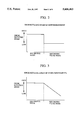
- FIG. 2 is a graph showing the rotating speed of the drum of the recording apparatus in accordance with the first aspect of the invention.
- FIG. 3 is a graph showing the rotating speed of the drum of an embodiment of the recording apparatus.
- FIG. 4 is a graph showing the rotating speed of the drum of another embodiment of the recording apparatus.
- FIG. 5 is a block diagram showing a portion of a reproducing apparatus in accordance with a second aspect of the invention.
- FIG. 6 is a graph showing the rotating speed of the drum of the reproducing apparatus in accordance with the second aspect of the invention.
- FIG. 7 is a graph showing the rotating speed of the drum of an embodiment of the reproducing apparatus.
- FIG. 8 is a graph showing the rotating speed of the drum of another embodiment of the reproducing apparatus.
- FIG. 1 is a block diagram showing the arrangement of a portion of a recording apparatus in accordance with a first aspect of the present invention, with the portion related to reproduction omitted.
- reference numeral 1 denotes a magnetic tape for recording and reproducing magnetic signals
- reference numeral 2 denotes a magnetic head for recording and reproducing signals on the magnetic tape 1
- reference numeral 3 denotes a drum provided with the magnetic head 2 rotating at a predetermined speed
- reference numeral 4 denotes a head amplifier which amplifies recorded and reproduced signals
- reference numeral 5 denotes a signal processing circuit which converts video signals to recorded signals and recorded signals back to video signals
- reference numeral 6 denotes an input/output terminal for signal input and output
- reference numeral 7 denotes a drum motor for rotating the drum 3
- reference numeral 8 denotes a drive circuit for controlling the drum motor 7
- reference numerals 9-1 and 9-2 each denote a change-over switch which interlocks for operation, with 9-1 being a switch for switching the rotating speed of the drum motor 7 and 9-2 being a switch for switching the rotating speed of capstan motor 11
- reference numeral 10 generally denotes a control circuit for the drum motor
- FIG. 2 is a graph showing the rotating speed of the drum 3 controlled by the drum motor control circuit 10 during a recording mode and a recording pause mode.
- switches 9-1 and 9-2 are connected to side a as shown in FIG. 1, and the drum motor 7 and the capstan motor 11 each rotate at the predetermined speed.
- signals input by input/output terminal 6 are recorded on the magnetic tape 1 by means of the magnetic head 2 mounted on the drum 3 by way of the signal processing circuit 5 and the head amplifier 4.
- switches 9-1 and 9-2 switch to side b as shown in FIG. 1.
- the capstan motor 11 stops, and the drum does not rotate at the same speed as it rotated during the recording pause mode, as shown in FIG. 2.
- the drum 3 in the recording pause mode of the recording apparatus in accordance with the first aspect of the present invention is set to rotate at a lower speed than during the recording mode, reducing the possibility of damage to and wearing of the magnetic tape 1 and the magnetic head 2.
- the rotating speed of the drum 3 in the recording pause mode is varied in a binary manner.
- the rotating speed of the drum 3 can be gradually reduced or reduced stepwise, with the same effects obtained as with a recording apparatus in accordance with the first aspect.
- FIG. 5 is a block diagram showing the arrangement of a portion of a reproducing apparatus in accordance with a second aspect of the present invention, with the portion related to recording not shown. Like or corresponding parts to those of the recording apparatus in accordance with the first aspect are designated using the same reference numerals.
- reference numeral 1 denotes a magnetic tape on which magnetic signals have been recorded
- reference numeral 2 denotes a magnetic head for reproducing signals recorded on the magnetic tape 1
- reference numeral 3 denotes a drum provided with a magnetic head 2 which rotates at a predetermined speed
- reference numeral 4 denotes a head amplifier which amplifies signals reproduced by the magnetic head 2
- reference numeral 5 denotes a signal processing circuit which converts amplified reproduced signals into video signals
- reference numeral 7 denotes a drum motor for rotating the drum 3
- reference numeral 8 denotes a drive circuit for controlling the drum motor 7
- reference numeral 11 denotes a capstan motor which runs the magnetic tape 1
- reference numeral 12 denotes a drive circuit for the capstan motor 11
- reference numerals 14-1, 14-2, and 14-3 each denote a switch which interlocks for operation, with switch 14-1 being used for controlling reproducing operations, switch 14-2 being used for switching signals input during a still picture reproducing (still
- FIG. 6 is a graph showing the rotating speed of the drum 3 during a still picture reproducing (still) mode and a motion picture reproducing (play) mode.
- switches 14-1, 14-2, and 14-3 each switches to side b shown in FIG. 5, causing the capstan motor 11 to stop.
- the video signals sent from the signal processing section 5 to the memory 16 reach the output terminal 17, which at the same time pass the feedback path 15 and reenter the memory 16, this operation loop being indefinitely repeated until the mode ends.
- the rotating speed which is set at a lower speed than during the motion picture reproducing (play) mode, can reduce damage to and wearing of the magnetic tape 1 and the magnetic head 2.
- the rotating speed of the drum during the still picture reproducing (still) mode has only been changed in a binary manner.
- the rotating speed of drum 3 can be reduced gradually or stepwise, with the same effects as those obtained in the reproducing apparatus in accordance with the second aspect.
- the drum rotation control means which controls the rotating speed of the drum having a magnetic head, rotates the drum at a lower speed than during a recording mode and interrupts the recording of signals while the magnetic head is kept in sliding contact with the magnetic recording medium.
- the drum is rotated by the drum rotation control means at a lower speed than during a still picture reproducing mode, interrupting the reproduction of signals recorded on the magnetic recording medium with the magnetic head kept in sliding contact on the magnetic recording medium to reproduce still pictures from signals recorded in the memory.
- the magnetic head and the magnetic recording medium slide at a lower speed than they rotate during the recording mode or during the motion picture reproducing mode, respectively, even when the magnetic recording medium does not run and the magnetic head slides on the same portion thereon; in other words, the number of times the head and medium slide against each other is less for the same length of time, thereby preventing, or at least reducing, damage to the magnetic recording medium and wearing of the magnetic head.
Landscapes
- Engineering & Computer Science (AREA)
- Signal Processing (AREA)
- Multimedia (AREA)
- Television Signal Processing For Recording (AREA)
Abstract
Description
Claims (18)
Applications Claiming Priority (2)
| Application Number | Priority Date | Filing Date | Title |
|---|---|---|---|
| JP4348673A JPH06203436A (en) | 1992-12-28 | 1992-12-28 | Magnetic recording device and magnetic reproducing device |
| JP4-348673 | 1992-12-28 |
Publications (1)
| Publication Number | Publication Date |
|---|---|
| US5606463A true US5606463A (en) | 1997-02-25 |
Family
ID=18398591
Family Applications (1)
| Application Number | Title | Priority Date | Filing Date |
|---|---|---|---|
| US08/174,010 Expired - Lifetime US5606463A (en) | 1992-12-28 | 1993-12-28 | Magnetic recording apparatus and magnetic reproducing apparatus |
Country Status (2)
| Country | Link |
|---|---|
| US (1) | US5606463A (en) |
| JP (1) | JPH06203436A (en) |
Citations (3)
| Publication number | Priority date | Publication date | Assignee | Title |
|---|---|---|---|---|
| US4161002A (en) * | 1977-01-08 | 1979-07-10 | Sony Corporation | Power conserving motor control circuit for a video tape recorder |
| US4772975A (en) * | 1985-07-22 | 1988-09-20 | Hitachi, Ltd. | Magnetic reproducing apparatus |
| US5285329A (en) * | 1989-09-29 | 1994-02-08 | Canon Kabushiki Kaisha | Rotary head type recording apparatus |
-
1992
- 1992-12-28 JP JP4348673A patent/JPH06203436A/en active Pending
-
1993
- 1993-12-28 US US08/174,010 patent/US5606463A/en not_active Expired - Lifetime
Patent Citations (3)
| Publication number | Priority date | Publication date | Assignee | Title |
|---|---|---|---|---|
| US4161002A (en) * | 1977-01-08 | 1979-07-10 | Sony Corporation | Power conserving motor control circuit for a video tape recorder |
| US4772975A (en) * | 1985-07-22 | 1988-09-20 | Hitachi, Ltd. | Magnetic reproducing apparatus |
| US5285329A (en) * | 1989-09-29 | 1994-02-08 | Canon Kabushiki Kaisha | Rotary head type recording apparatus |
Also Published As
| Publication number | Publication date |
|---|---|
| JPH06203436A (en) | 1994-07-22 |
Similar Documents
| Publication | Publication Date | Title |
|---|---|---|
| US4649442A (en) | Automatic program selector of a video tape recorder | |
| KR960016493B1 (en) | Recorder | |
| KR100858762B1 (en) | Video tape recorder and video tape recorder | |
| US5606463A (en) | Magnetic recording apparatus and magnetic reproducing apparatus | |
| JPS5931137B2 (en) | magnetic tape device | |
| US5107380A (en) | Rotary head type recording or reproducing apparatus detecting the slack of the recording medium | |
| JPS60258759A (en) | High density recording disc reproducing device | |
| JP2955303B2 (en) | Magnetic recording / reproducing device | |
| JP2680410B2 (en) | Magnetic recording / reproducing device | |
| JPS61110357A (en) | Recording/playback device | |
| US20030223146A1 (en) | Magnetic record and playback device | |
| JPS6215887Y2 (en) | ||
| KR960006676B1 (en) | Mode processing method for vcr | |
| JP2900568B2 (en) | Video recording and playback device | |
| JPH04184752A (en) | Recording or playback device | |
| JPH0534740B2 (en) | ||
| JPH07121947A (en) | Control method for high-speed search | |
| EP0428145A2 (en) | Tape reproducing apparatus | |
| JPH04278277A (en) | Recording/playback device for tape-shaped recording media | |
| KR19990050151A (en) | Digital Video Camcorder Recording Device Using 1/2 Inch Tape | |
| JPH04219602A (en) | Information reproducing and recording device for tape-shaped recording media | |
| JPH052798A (en) | Tape drive | |
| JPS63261561A (en) | Unrecorded section cue method | |
| JPH0442422A (en) | rotating head drum device | |
| JPH04121854A (en) | Magnetic recording and reproducing device |
Legal Events
| Date | Code | Title | Description |
|---|---|---|---|
| AS | Assignment |
Owner name: CANON KABUSHIKI KAISHA, JAPAN Free format text: ASSIGNMENT OF ASSIGNORS INTEREST;ASSIGNOR:NIWA, HIROFUMI;REEL/FRAME:006821/0288 Effective date: 19931221 |
|
| STCF | Information on status: patent grant |
Free format text: PATENTED CASE |
|
| CC | Certificate of correction | ||
| FEPP | Fee payment procedure |
Free format text: PAYOR NUMBER ASSIGNED (ORIGINAL EVENT CODE: ASPN); ENTITY STATUS OF PATENT OWNER: LARGE ENTITY Free format text: PAYER NUMBER DE-ASSIGNED (ORIGINAL EVENT CODE: RMPN); ENTITY STATUS OF PATENT OWNER: LARGE ENTITY |
|
| FPAY | Fee payment |
Year of fee payment: 4 |
|
| FPAY | Fee payment |
Year of fee payment: 8 |
|
| FPAY | Fee payment |
Year of fee payment: 12 |