US5595057A - Steel cords for the reinforcement of rubber articles - Google Patents
Steel cords for the reinforcement of rubber articles Download PDFInfo
- Publication number
- US5595057A US5595057A US08/393,893 US39389395A US5595057A US 5595057 A US5595057 A US 5595057A US 39389395 A US39389395 A US 39389395A US 5595057 A US5595057 A US 5595057A
- Authority
- US
- United States
- Prior art keywords
- sheath
- filament
- cord
- twisting
- filaments
- Prior art date
- Legal status (The legal status is an assumption and is not a legal conclusion. Google has not performed a legal analysis and makes no representation as to the accuracy of the status listed.)
- Expired - Lifetime
Links
Images

Classifications
-
- D—TEXTILES; PAPER
- D07—ROPES; CABLES OTHER THAN ELECTRIC
- D07B—ROPES OR CABLES IN GENERAL
- D07B1/00—Constructional features of ropes or cables
- D07B1/06—Ropes or cables built-up from metal wires, e.g. of section wires around a hemp core
- D07B1/0606—Reinforcing cords for rubber or plastic articles
- D07B1/062—Reinforcing cords for rubber or plastic articles the reinforcing cords being characterised by the strand configuration
- D07B1/0633—Reinforcing cords for rubber or plastic articles the reinforcing cords being characterised by the strand configuration having a multiple-layer configuration
-
- B—PERFORMING OPERATIONS; TRANSPORTING
- B60—VEHICLES IN GENERAL
- B60C—VEHICLE TYRES; TYRE INFLATION; TYRE CHANGING; CONNECTING VALVES TO INFLATABLE ELASTIC BODIES IN GENERAL; DEVICES OR ARRANGEMENTS RELATED TO TYRES
- B60C9/00—Reinforcements or ply arrangement of pneumatic tyres
- B60C9/02—Carcasses
- B60C9/04—Carcasses the reinforcing cords of each carcass ply arranged in a substantially parallel relationship
-
- D—TEXTILES; PAPER
- D07—ROPES; CABLES OTHER THAN ELECTRIC
- D07B—ROPES OR CABLES IN GENERAL
- D07B1/00—Constructional features of ropes or cables
- D07B1/06—Ropes or cables built-up from metal wires, e.g. of section wires around a hemp core
- D07B1/0606—Reinforcing cords for rubber or plastic articles
- D07B1/062—Reinforcing cords for rubber or plastic articles the reinforcing cords being characterised by the strand configuration
- D07B1/0626—Reinforcing cords for rubber or plastic articles the reinforcing cords being characterised by the strand configuration the reinforcing cords consisting of three core wires or filaments and at least one layer of outer wires or filaments, i.e. a 3+N configuration
-
- D—TEXTILES; PAPER
- D07—ROPES; CABLES OTHER THAN ELECTRIC
- D07B—ROPES OR CABLES IN GENERAL
- D07B1/00—Constructional features of ropes or cables
- D07B1/06—Ropes or cables built-up from metal wires, e.g. of section wires around a hemp core
- D07B1/0606—Reinforcing cords for rubber or plastic articles
- D07B1/0646—Reinforcing cords for rubber or plastic articles comprising longitudinally preformed wires
-
- B—PERFORMING OPERATIONS; TRANSPORTING
- B60—VEHICLES IN GENERAL
- B60C—VEHICLE TYRES; TYRE INFLATION; TYRE CHANGING; CONNECTING VALVES TO INFLATABLE ELASTIC BODIES IN GENERAL; DEVICES OR ARRANGEMENTS RELATED TO TYRES
- B60C9/00—Reinforcements or ply arrangement of pneumatic tyres
- B60C9/02—Carcasses
- B60C9/04—Carcasses the reinforcing cords of each carcass ply arranged in a substantially parallel relationship
- B60C2009/0416—Physical properties or dimensions of the carcass cords
- B60C2009/0425—Diameters of the cords; Linear density thereof
-
- B—PERFORMING OPERATIONS; TRANSPORTING
- B60—VEHICLES IN GENERAL
- B60C—VEHICLE TYRES; TYRE INFLATION; TYRE CHANGING; CONNECTING VALVES TO INFLATABLE ELASTIC BODIES IN GENERAL; DEVICES OR ARRANGEMENTS RELATED TO TYRES
- B60C9/00—Reinforcements or ply arrangement of pneumatic tyres
- B60C9/02—Carcasses
- B60C9/04—Carcasses the reinforcing cords of each carcass ply arranged in a substantially parallel relationship
- B60C2009/0416—Physical properties or dimensions of the carcass cords
- B60C2009/0458—Elongation of the reinforcements at break point
-
- D—TEXTILES; PAPER
- D07—ROPES; CABLES OTHER THAN ELECTRIC
- D07B—ROPES OR CABLES IN GENERAL
- D07B2201/00—Ropes or cables
- D07B2201/20—Rope or cable components
- D07B2201/2001—Wires or filaments
- D07B2201/2007—Wires or filaments characterised by their longitudinal shape
- D07B2201/2008—Wires or filaments characterised by their longitudinal shape wavy or undulated
-
- D—TEXTILES; PAPER
- D07—ROPES; CABLES OTHER THAN ELECTRIC
- D07B—ROPES OR CABLES IN GENERAL
- D07B2201/00—Ropes or cables
- D07B2201/20—Rope or cable components
- D07B2201/2015—Strands
- D07B2201/2023—Strands with core
-
- D—TEXTILES; PAPER
- D07—ROPES; CABLES OTHER THAN ELECTRIC
- D07B—ROPES OR CABLES IN GENERAL
- D07B2201/00—Ropes or cables
- D07B2201/20—Rope or cable components
- D07B2201/2015—Strands
- D07B2201/2024—Strands twisted
- D07B2201/2029—Open winding
- D07B2201/203—Cylinder winding, i.e. S/Z or Z/S
-
- D—TEXTILES; PAPER
- D07—ROPES; CABLES OTHER THAN ELECTRIC
- D07B—ROPES OR CABLES IN GENERAL
- D07B2201/00—Ropes or cables
- D07B2201/20—Rope or cable components
- D07B2201/2015—Strands
- D07B2201/2024—Strands twisted
- D07B2201/2029—Open winding
- D07B2201/2031—Different twist pitch
- D07B2201/2032—Different twist pitch compared with the core
-
- D—TEXTILES; PAPER
- D07—ROPES; CABLES OTHER THAN ELECTRIC
- D07B—ROPES OR CABLES IN GENERAL
- D07B2201/00—Ropes or cables
- D07B2201/20—Rope or cable components
- D07B2201/2015—Strands
- D07B2201/2038—Strands characterised by the number of wires or filaments
- D07B2201/204—Strands characterised by the number of wires or filaments nine or more wires or filaments respectively forming multiple layers
-
- D—TEXTILES; PAPER
- D07—ROPES; CABLES OTHER THAN ELECTRIC
- D07B—ROPES OR CABLES IN GENERAL
- D07B2201/00—Ropes or cables
- D07B2201/20—Rope or cable components
- D07B2201/2047—Cores
- D07B2201/2052—Cores characterised by their structure
- D07B2201/2059—Cores characterised by their structure comprising wires
- D07B2201/2061—Cores characterised by their structure comprising wires resulting in a twisted structure
-
- D—TEXTILES; PAPER
- D07—ROPES; CABLES OTHER THAN ELECTRIC
- D07B—ROPES OR CABLES IN GENERAL
- D07B2201/00—Ropes or cables
- D07B2201/20—Rope or cable components
- D07B2201/2095—Auxiliary components, e.g. electric conductors or light guides
- D07B2201/2097—Binding wires
-
- D—TEXTILES; PAPER
- D07—ROPES; CABLES OTHER THAN ELECTRIC
- D07B—ROPES OR CABLES IN GENERAL
- D07B2401/00—Aspects related to the problem to be solved or advantage
- D07B2401/20—Aspects related to the problem to be solved or advantage related to ropes or cables
- D07B2401/2065—Reducing wear
- D07B2401/207—Reducing wear internally
-
- D—TEXTILES; PAPER
- D07—ROPES; CABLES OTHER THAN ELECTRIC
- D07B—ROPES OR CABLES IN GENERAL
- D07B2501/00—Application field
- D07B2501/20—Application field related to ropes or cables
- D07B2501/2046—Tire cords
-
- Y—GENERAL TAGGING OF NEW TECHNOLOGICAL DEVELOPMENTS; GENERAL TAGGING OF CROSS-SECTIONAL TECHNOLOGIES SPANNING OVER SEVERAL SECTIONS OF THE IPC; TECHNICAL SUBJECTS COVERED BY FORMER USPC CROSS-REFERENCE ART COLLECTIONS [XRACs] AND DIGESTS
- Y10—TECHNICAL SUBJECTS COVERED BY FORMER USPC
- Y10S—TECHNICAL SUBJECTS COVERED BY FORMER USPC CROSS-REFERENCE ART COLLECTIONS [XRACs] AND DIGESTS
- Y10S57/00—Textiles: spinning, twisting, and twining
- Y10S57/902—Reinforcing or tire cords
Definitions
- This invention relates to steel cords for the reinforcement of rubber articles such as pneumatic tires, industrial belts and the like and pneumatic radial tires using the same as a carcass ply for the improvement of tire durability.
- a typical example of rubber articles reinforced with steel cords are known pneumatic tires.
- the tires for truck, bus and light truck use are common and have a carcass ply comprised of steel cords having a two or three layer twisting structure or so-called multilayer twisting structure.
- an object of the invention to improve the durability of the steel cord for the reinforcement of rubber articles by uniformly and gently proceeding the decrease of sectional area in the filaments constituting the cord based on fretting wear to equalize the decrease of tenacity in each of these filaments.
- the inventors have made various studies with respect to the steel cords of multilayer twisting structure used in a heavy duty pneumatic tire, particularly steel cord of 3+9+15+1 structure causing the decrease of tenacity during the running of the tire when such steel cords are used in the carcass ply of the tire.
- the decrease of tenacity in the filament constituting the outermost layer of the cord is very large and the main cause of decreasing the tenacity is fretting wear between the filament in the outer most layer and a wrap filament required for ensuring restraint of the filaments in this type of the cord and spirally wound around the outer periphery of the cord.
- warp or torsion is caused in a layer used in, for example, a carcass ply of a tire, which considerably obstructs the assembling operability of a green tire. That is, the layers formed by coating a plurality of steel cords arranged in parallel to each other with rubber is cut into a given length and joined to each other for the formation of the carcass ply or belt layer.
- the steel cord having no restraint through the wrap filament there is caused a phenomenon that the end portion of the layer after cutting is warped upward or downward or only the corner of the cut end portion is warped to form torsion.
- a steel cord for the reinforcement of rubber articles comprising: a core comprised of three steel filaments, a first sheath formed by twisting nine wave-formed steel filaments around the core, and a second sheath formed by twisting fifteen wave-formed steel filaments around the first sheath in a direction opposite to the twisting direction of the first sheath, in which a forming ratio F 1 of each filament in the first sheath defined by a ratio of amplitude H 1 of wave formed in the filament to ideal diameter D 1 of the first sheath and a forming ratio F 2 of each filament in the second sheath defined by a ratio of amplitude H 2 of wave formed in the filament to ideal diameter D 2 of the second sheath are within a range of 0.75-0.95, respectively, and satisfy F 1 ⁇ F 2 .
- each filament constituting the cord has naturally a certain twisting angle, so that a sectional shape of the cord in a direction perpendicular to the longitudinal direction of the cord is ellipsoidal near to circle.
- the ideal diameter of each sheath is calculated according to the following equations:
- r 2 diameter of filament in second sheath (mm).
- the invention provides a pneumatic radial tire comprising a carcass of at least one carcass ply toroidally extending between a pair of bead portions, in which the carcass ply contains the above defined steel cords.
- FIG. 1 is a diagrammatically sectional view of a steel cord having a 3+9+15 layer twisting structure according to the invention
- FIG. 2 is a schematic view illustrating an amplitude of a wave-formed steel filament
- FIG. 3 is a section view of an embodiment of the pneumatic radial tire according to the invention.
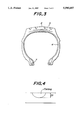
- FIG. 4 is a schematic view illustrating a fretting depth of the steel filament.
- FIG. 1 is sectionally shown a steel cord for the reinforcement of rubber articles according to the invention.
- Each of the filaments constituting the first sheath and second sheath is subjected to wave forming as shown in FIG. 2, whereby the operability in the formation of the second sheath 3 around the first sheath 2 is improved and also the restraint of the filaments in the cord after the twisting is ensured.
- a forming ratio F 1 of each filament in the first sheath defined by a ratio of amplitude H 1 of wave formed in the filament to ideal diameter D 1 of the first sheath and a forming ratio F 2 of each filament in the second sheath defined by a ratio of amplitude H 2 of wave formed in the filament to ideal diameter D 2 of the second sheath are within a range of 0.75-0.95, respectively, and satisfy F 1 ⁇ F 2 .
- the steel cords according to the invention are applicable to a carcass 4 in a pneumatic radial tire as shown, for example, in FIG. 3.
- numeral 5 designates belt layers covering a crown portion of the carcass 4
- numeral 6 a tread portion superimposed about the belt layers 5
- numeral 7 a bead core.
- the lowering of filament tenacity in the steel cord of the layer twisting structure, particularly the lowering of filament tenacity in the outermost layer is due to fretting wear created between the wrap filament and the filament in the outermost layer, for example, during the running of the tire. Because, the contact area between the wrap filament and the filament in the outermost layer is small, the contact pressure per unit area becomes large to create the fretting wear.
- torsion is caused in the cords of the carcass ply at the ground contact region of the tire.
- torsion is caused in a direction opposite to the twisting direction of the outermost layer
- the wrap filament is wound in a direction opposite to the twisting direction of the filaments constituting the outermost layer
- torsion is caused in the wrap filament toward the same direction as the twisting direction of the filaments in the outermost layer.
- the wrap filament and the filaments of the outermost layer move in opposite directions to each other. Since the contact pressure per unit area is large, the decrease of sectional area in the filament in the outermost layer due to the fretting with the wrap filament is promoted by such an opposite movement to inevitably cause the lowering of filament tenacity.
- the filaments of the second sheath restrain the filaments of the first sheath and develop the same restraining effect as in the wrap filament. Furthermore, the number of the filaments is large and the twisting pitch is long in the filaments of the second sheath bearing the restraint as compared with the wrap filament bearing the restraint. Thus, the contact pressure between the filaments of the second sheath becomes low and the lowering of filament tenacity due to the fretting wear becomes negligible.
- the forming ratio F 1 of each filament in the first sheath and the forming ratio F 2 of each filament in the second sheath are within a range of 0.75-0.95, preferably 0.85-0.95, respectively, and satisfy F 1 ⁇ F 2 , the restraint between the filaments in the cord becomes more sure and rigid and hence the stability to torsion of the cord itself or the resistance to torsion or disentanglement is improved.
- the restraint in the cord is rationalized, so that it is effective to improve the operability in factory manufacturing. Because, when the restraint in the cord is not adequate as mentioned above, the cord is apt to cause torsion and hence warp or torsion is created in the layer formed by coating the cords with rubber to bring about the increase of fraction defective and the lowering of productivity.
- the cords of so-called rubber penetration structure in which rubber is penetrated into gap between filaments in outermost sheath layer as proposed in JP-A-5-179584 or the like tend to prolong the service life of the cord in the large bending input because the restraint through rubber is applied to the outermost sheath layer.
- the range of causing fretting wear is increased owing to the presence of the gaps between the filaments in the sheath for the formation of rubber penetration structure as compared with the cord of compactly twisted structure, which is unfavorable from a viewpoint of cord durability and tends to lower the resistance to corrosion fatigue.
- the mutual tightening effect by differing the twisting directions of the second sheath and the first sheath may be observed even in the two-layer twisted cord.
- the difference in the number of filaments between the core and the sheath is large, so that the force of controlling the disentangling of the sheath is small and the effect is less.
- the filament diameter is less than 0.220 mm.
- the lower limit of filament diameter is favorable to be 0.150 mm in view of the productivity and production cost.
- a pneumatic radial tire for truck and bus having a tire size of 1000R20 16PR and a tire structure as shown in FIG. 3 is manufactured by applying each of steel cords as shown in Tables 1 and 2 to a carcass ply of the tire at an end count of 22.0 cords/5 cm.
- the retention of cord tenacity is evaluated as follows: that is, the test tire inflated under an internal pressure of 8 kgf/cm 2 is run at a speed of 60 km/h under JIS 100% load over a distance of 300,000 km by conducting retreading every a running distance of 100,000 km and thereafter the sample of the rubberized steel cord is taken out from the carcass ply of the test tire after the running and placed on an Instron tensile testing machine to measure the tensile strength of the sample.
- the retention of cord tenacity (%) is calculated by a ratio of the measured value to a value of tensile strength of the cord before assembling into the tire.
- the calculated value is represented by an index on the basis that the result of Comparative Example 1 is 100. The larger the index value, the better the retention of cord tenacity.
- the percentage of filament breakage is represented by a percentage of the number of broken filaments in 10 cords taken out from the carcass ply after the test tire is run on a drum under an internal pressure of 1 kgf/cm 2 over a distance of 10,000 km to the total number of filaments in 10 cords.
- a percentage of filament breakage of not more than 10% is preferable.
- the fretting depth is measured as follows. After the test tire is run on the drum over a distance of 100,000 km under the same conditions as in the retention of cord tenacity, two steel filaments in each of the first and second sheaths are taken out from the steel cord in the carcass ply of the tire and a quantity of filament diameter D f reduced due to fretting wear as shown in FIG. 4 is measured every filament within a region of 13 cm ⁇ 2 cm from the widthwise center of the tread. A maximum value among the measured values is evaluated as the fretting depth. The smaller the numerical value, the better the resistance to fretting wear.
- the fretting depth is desirable to be not more than 20 ⁇ m.
- the fraction defective and productivity of the layer containing steel cords at each production step of from twisting step to the tire build-up step are evaluated by three stages, in which symbol ⁇ is no problem, symbol ⁇ a partly problem (e.g. it is required to remove the catching of the transporting layer) and symbol X a great problem (e.g. the operation is delayed due to the catching of the layer in a tire building machine or the poor joint between the layers lowers the assembling accuracy of the green tire).
- Comparative Examples 1, 4 and 6 are good in the operability in factory manufacture owing to the restraint through the wrap filament, but are large in the fretting depth. In Comparative Examples 2 and 5, the fretting depth is small, but the operability in factory is poor. In Comparative Example 3, the effect is less though the twisting directions of the core and the sheath are opposite. In Comparative Examples 7 and 8, the forming ratio of the filament in the sheath is outside the range defined in the invention, so that the operability in factory is poor.
- the fretting wear between the filament in the outermost sheath layer and the wrap filament is eliminated and the tenacity of the filament in the cord is proceeded uniformly and gently to improve the service life of the cord.
- the durability of the rubber article reinforced with such steel cords e.g. the durability of the pneumatic tire can be improved.
Abstract
A steel cord for the reinforcement of rubber articles comprises a core comprised of three steel filaments, a first sheath formed by twisting nine wave-formed steel filaments around the core, and a second sheath formed by twisting fifteen wave-formed steel filaments around the first sheath in a direction opposite to the twisting direction of the first sheath, in which a forming ratio F1 of each filament in the first sheath and a forming ratio F2 of each filament in the second sheath are within a range of 0.75-0.95, respectively, and satisfy Fi1 <F2.
Description
1. Field of the Invention
This invention relates to steel cords for the reinforcement of rubber articles such as pneumatic tires, industrial belts and the like and pneumatic radial tires using the same as a carcass ply for the improvement of tire durability.
2. Description of the Related Art
A typical example of rubber articles reinforced with steel cords, are known pneumatic tires. Among these tires, the tires for truck, bus and light truck use are common and have a carcass ply comprised of steel cords having a two or three layer twisting structure or so-called multilayer twisting structure.
In general, bending deformation is caused in the steel cord as a reinforcing material during the running of the tire, and hence fretting wear is created in each filament constituting the steel cord to inevitably decrease the sectional area of the filament and lower the tenacity of the steel cord.
If the decrease of sectional area in a portion of the filaments constituting the steel cord is violent, such a filament is apt to cause breakage to shock in tension or repetitive bending. Once the filament is broken, tensile stress increases in the remaining filaments to promote fatigue breakage of the steel cord. Therefore, in order to improve the durability of the steel cord, it is effective to avoid the premature breakage in a portion of the filaments and also it is desirable that the lowering of tenacity in all filaments constituting the steel cord is same.
It is, therefore, an object of the invention to improve the durability of the steel cord for the reinforcement of rubber articles by uniformly and gently proceeding the decrease of sectional area in the filaments constituting the cord based on fretting wear to equalize the decrease of tenacity in each of these filaments.
The inventors have made various studies with respect to the steel cords of multilayer twisting structure used in a heavy duty pneumatic tire, particularly steel cord of 3+9+15+1 structure causing the decrease of tenacity during the running of the tire when such steel cords are used in the carcass ply of the tire. As a result, it has been found that the decrease of tenacity in the filament constituting the outermost layer of the cord is very large and the main cause of decreasing the tenacity is fretting wear between the filament in the outer most layer and a wrap filament required for ensuring restraint of the filaments in this type of the cord and spirally wound around the outer periphery of the cord.
Now, the inventors have made further studies with respect to the steel cords removing the wrap filament for avoiding fretting wear and found that fretting wear through the wrap filament is naturally eliminated and the decrease of tenacity of the filament in the outermost layer can be suppressed. However the restraint of the filaments in the cord is lowered due to the absence of the wrap filament and these filaments are scattered when the cord is extremely bent. Hence, a phenomenon of breaking a part of the filaments due to abnormal input is caused to largely lower the service life of the cord as compared with the cord having a wrap filament. In order to prevent the lowering of the service life in the cord having no wrap filament due to the extreme bending input, therefore, it is required to ensure the restraint of the filaments constituting the cord.
If the restraint through the wrap filament is omitted, warp or torsion is caused in a layer used in, for example, a carcass ply of a tire, which considerably obstructs the assembling operability of a green tire. That is, the layers formed by coating a plurality of steel cords arranged in parallel to each other with rubber is cut into a given length and joined to each other for the formation of the carcass ply or belt layer. However, when using the steel cord having no restraint through the wrap filament, there is caused a phenomenon that the end portion of the layer after cutting is warped upward or downward or only the corner of the cut end portion is warped to form torsion. As a result, the transportation of the layer is obstructed due to the presence of warp or torsion, or it is impossible to join the layers to each other, so that the assembling accuracy of the green tire lowers and the operability thereof lowers. Even in the cord having no wrap filament, it is required to restrain the filaments constituting the cord.
That is, the invention has been accomplished based on the above knowledge.
According to the invention, there is the provision of a steel cord for the reinforcement of rubber articles comprising: a core comprised of three steel filaments, a first sheath formed by twisting nine wave-formed steel filaments around the core, and a second sheath formed by twisting fifteen wave-formed steel filaments around the first sheath in a direction opposite to the twisting direction of the first sheath, in which a forming ratio F1 of each filament in the first sheath defined by a ratio of amplitude H1 of wave formed in the filament to ideal diameter D1 of the first sheath and a forming ratio F2 of each filament in the second sheath defined by a ratio of amplitude H2 of wave formed in the filament to ideal diameter D2 of the second sheath are within a range of 0.75-0.95, respectively, and satisfy F1 <F2.
In the steel cord of the above structure, each filament constituting the cord has naturally a certain twisting angle, so that a sectional shape of the cord in a direction perpendicular to the longitudinal direction of the cord is ellipsoidal near to circle. When such a shape is considered as a circle, the ideal diameter of each sheath is calculated according to the following equations:
D.sub.1 =(2√3/3+1)xr.sub.c +2xr.sub.1
D.sub.2 =(2√3/3+1)xr.sub.c +2xr.sub.1 +2xr.sub.2
where
rc : diameter of filament in core (mm)
r1 : diameter of filament in first sheath (mm)
r2 : diameter of filament in second sheath (mm).
Furthermore, the invention provides a pneumatic radial tire comprising a carcass of at least one carcass ply toroidally extending between a pair of bead portions, in which the carcass ply contains the above defined steel cords.
The invention will be described with reference to the accompanying drawings, wherein:
FIG. 1 is a diagrammatically sectional view of a steel cord having a 3+9+15 layer twisting structure according to the invention;
FIG. 2 is a schematic view illustrating an amplitude of a wave-formed steel filament;
FIG. 3 is a section view of an embodiment of the pneumatic radial tire according to the invention; and
FIG. 4 is a schematic view illustrating a fretting depth of the steel filament.
In FIG. 1 is sectionally shown a steel cord for the reinforcement of rubber articles according to the invention. Three steel filaments shown by oblique lines in FIG. 1 with core 1 as a central base structure of the cord, and a first sheath 2 formed by coaxially twisting nine steel filaments around the core 1 so as to arrange these filaments adjacent to each other, and a second sheath 3 formed by twisting fifteen steel filaments around the first sheath in a direction opposite to the twisting direction of the first sheath 2.
Each of the filaments constituting the first sheath and second sheath is subjected to wave forming as shown in FIG. 2, whereby the operability in the formation of the second sheath 3 around the first sheath 2 is improved and also the restraint of the filaments in the cord after the twisting is ensured.
In forming the filaments for the first and second sheaths 2, 3, it is necessary that a forming ratio F1 of each filament in the first sheath defined by a ratio of amplitude H1 of wave formed in the filament to ideal diameter D1 of the first sheath and a forming ratio F2 of each filament in the second sheath defined by a ratio of amplitude H2 of wave formed in the filament to ideal diameter D2 of the second sheath are within a range of 0.75-0.95, respectively, and satisfy F1 <F2.
Furthermore, the steel cords according to the invention are applicable to a carcass 4 in a pneumatic radial tire as shown, for example, in FIG. 3. In FIG. 3, numeral 5 designates belt layers covering a crown portion of the carcass 4, numeral 6 a tread portion superimposed about the belt layers 5, and numeral 7 a bead core.
As previously mentioned, the lowering of filament tenacity in the steel cord of the layer twisting structure, particularly the lowering of filament tenacity in the outermost layer is due to fretting wear created between the wrap filament and the filament in the outermost layer, for example, during the running of the tire. Because, the contact area between the wrap filament and the filament in the outermost layer is small, the contact pressure per unit area becomes large to create the fretting wear.
In case of turning the tire, torsion is caused in the cords of the carcass ply at the ground contact region of the tire. When such torsion is caused in a direction opposite to the twisting direction of the outermost layer, if the wrap filament is wound in a direction opposite to the twisting direction of the filaments constituting the outermost layer, torsion is caused in the wrap filament toward the same direction as the twisting direction of the filaments in the outermost layer. Hence, the wrap filament and the filaments of the outermost layer move in opposite directions to each other. Since the contact pressure per unit area is large, the decrease of sectional area in the filament in the outermost layer due to the fretting with the wrap filament is promoted by such an opposite movement to inevitably cause the lowering of filament tenacity.
For this end, when the wrap filament is removed from the cord of the layer twisting structure, the lowering of the filament tenacity in the outermost layer is avoided. However, when the twisting direction of each sheath in the cord is same, if the large bending input is applied as previously mentioned, the filaments of these sheaths are scattered and consequently a portions of these filaments is broken due to the abnormal input and finally the service life of the cord can not be improved.
On the contrary, when the steel cord having a 3+9+15 layer twisting structure is formed by removing the wrap filament, if the twisting direction of the first sheath is opposite to the twisting direction of the second sheath, the filaments of the second sheath restrain the filaments of the first sheath and develop the same restraining effect as in the wrap filament. Furthermore, the number of the filaments is large and the twisting pitch is long in the filaments of the second sheath bearing the restraint as compared with the wrap filament bearing the restraint. Thus, the contact pressure between the filaments of the second sheath becomes low and the lowering of filament tenacity due to the fretting wear becomes negligible.
Further, when the direction of torsion applied to the filaments of the second sheath is the same as in the twisting direction of these filaments, there is not naturally caused problem. On the other hand, when the torsion is applied in a direction opposite to the twisting direction of the second sheath, torsion is caused in the first sheath in a direction opposite to the twisting direction of the second sheath to control the movement of disentangling the first sheath, which acts to restrain the second sheath. As a result, the first sheath and the second sheath exert a restraining force upon each other to maintain the restraint between the filaments in each sheath of the cord.
According to the invention, when the forming ratio F1 of each filament in the first sheath and the forming ratio F2 of each filament in the second sheath are within a range of 0.75-0.95, preferably 0.85-0.95, respectively, and satisfy F1 <F2, the restraint between the filaments in the cord becomes more sure and rigid and hence the stability to torsion of the cord itself or the resistance to torsion or disentanglement is improved.
Additionally, the restraint in the cord is rationalized, so that it is effective to improve the operability in factory manufacturing. Because, when the restraint in the cord is not adequate as mentioned above, the cord is apt to cause torsion and hence warp or torsion is created in the layer formed by coating the cords with rubber to bring about the increase of fraction defective and the lowering of productivity.
Incidentally, the cords of so-called rubber penetration structure in which rubber is penetrated into gap between filaments in outermost sheath layer as proposed in JP-A-5-179584 or the like tend to prolong the service life of the cord in the large bending input because the restraint through rubber is applied to the outermost sheath layer. However, the range of causing fretting wear is increased owing to the presence of the gaps between the filaments in the sheath for the formation of rubber penetration structure as compared with the cord of compactly twisted structure, which is unfavorable from a viewpoint of cord durability and tends to lower the resistance to corrosion fatigue.
Moreover, the mutual tightening effect by differing the twisting directions of the second sheath and the first sheath may be observed even in the two-layer twisted cord. In the latter case, the difference in the number of filaments between the core and the sheath is large, so that the force of controlling the disentangling of the sheath is small and the effect is less.
In order to prevent breakage of the filament in the cord, it is preferable to reduce the surface strain. In general, the surface strain of the filament ε is approximated by ε=D/2R (wherein D is a filament diameter, and R is a radius of curvature in the bending of the cord). Therefore, in order to reduce the surface strain ε under a certain bending input R, it is favorable to make the filament diameter D as fine as possible.
That is, in order to prevent the breakage of the filament against the extreme bending input applied to the carcass ply of the heavy duty pneumatic radial tire, in the cord exhibiting the effect according to the invention, it is favorable that the filament diameter is less than 0.220 mm. On the other hand, the lower limit of filament diameter is favorable to be 0.150 mm in view of the productivity and production cost. Further-more, in order to make the filament diameter as finer as possible and ensure the required cord tenacity, it is preferable to use a so-called high-strength steel material in which the tensile strength of the filament per unit sectional area is not less than 330 kgf/mm2.
The following examples are given in illustration of the invention and are not intended as limitations thereof.
A pneumatic radial tire for truck and bus having a tire size of 1000R20 16PR and a tire structure as shown in FIG. 3 is manufactured by applying each of steel cords as shown in Tables 1 and 2 to a carcass ply of the tire at an end count of 22.0 cords/5 cm.
The retention of cord tenacity, percentage of filament breakage, fretting depth and operability in factory are measured with respect to the resulting tire to obtain results as shown in Tables 1 and 2.
The retention of cord tenacity is evaluated as follows: that is, the test tire inflated under an internal pressure of 8 kgf/cm2 is run at a speed of 60 km/h under JIS 100% load over a distance of 300,000 km by conducting retreading every a running distance of 100,000 km and thereafter the sample of the rubberized steel cord is taken out from the carcass ply of the test tire after the running and placed on an Instron tensile testing machine to measure the tensile strength of the sample. The retention of cord tenacity (%) is calculated by a ratio of the measured value to a value of tensile strength of the cord before assembling into the tire. The calculated value is represented by an index on the basis that the result of Comparative Example 1 is 100. The larger the index value, the better the retention of cord tenacity.
The percentage of filament breakage is represented by a percentage of the number of broken filaments in 10 cords taken out from the carcass ply after the test tire is run on a drum under an internal pressure of 1 kgf/cm2 over a distance of 10,000 km to the total number of filaments in 10 cords. The smaller the numerical value, the better the resistance to filament breakage. Particularly, a percentage of filament breakage of not more than 10% is preferable.
The fretting depth is measured as follows. After the test tire is run on the drum over a distance of 100,000 km under the same conditions as in the retention of cord tenacity, two steel filaments in each of the first and second sheaths are taken out from the steel cord in the carcass ply of the tire and a quantity of filament diameter Df reduced due to fretting wear as shown in FIG. 4 is measured every filament within a region of 13 cm±2 cm from the widthwise center of the tread. A maximum value among the measured values is evaluated as the fretting depth. The smaller the numerical value, the better the resistance to fretting wear. The fretting depth is desirable to be not more than 20 μm.
In the operability in factory manufacture, the fraction defective and productivity of the layer containing steel cords at each production step of from twisting step to the tire build-up step are evaluated by three stages, in which symbol ∘ is no problem, symbol Δ a partly problem (e.g. it is required to remove the catching of the transporting layer) and symbol X a great problem (e.g. the operation is delayed due to the catching of the layer in a tire building machine or the poor joint between the layers lowers the assembling accuracy of the green tire).
                                  TABLE 1
__________________________________________________________________________
         Compar-
               Compar-
                    Compar-
                         Compar-  Compar-
                                        Compar-
         ative ative
                    ative
                         ative    ative ative
         Example
               Example
                    Example
                         Example  Example
                                        Example
         1     2    3    4        5     6
__________________________________________________________________________
Twisting 3 + 9 + 1
               3 + 9
                    3 + 9
                         3 + 9 + 15 + 1
                                  3 + 9 + 15
                                        3 + 9 + 13
structure
Filament 0.22  0.22 0.22 0.17     0.17  0.17
diameter
Twisting S/S/Z S/S  S/Z  S/S/Z/S  S/S/S S/S/Z
direction
Twisting pitch
         6/12/3.5
               6/12 6/12 5/10/15/3.5
                                  5/10/15
                                        5/10/15
(mm)
F.sub.1  0.95  0.94 0.95 0.82     0.85  0.86
F.sub.2  0.94  0.94 0.95 0.63     0.91  0.88
Retention of
         91    98   93   87       97    92
cord tenacity
Percentage of
         43    100  78   14       17    4
filament
breakage (%)
Fretting depth
         37    7    19   34       11    28
(max value: μm)
Operability in
         ∘
               x    Δ
                         ∘
                                  x     ∘
factory
__________________________________________________________________________
                                  TABLE 2
__________________________________________________________________________
           Compar-
                 Compar-
                       Accept-
                             Accept-
                                   Accept-
                                         Accept-
           ative ative able  able  able  able
           Example
                 Example
                       Example
                             Example
                                   Example
                                         Example
           7     8     1     2     3     4
__________________________________________________________________________
Twisting structure
           3 + 9 + 15
                 3 + 9 + 15
                       3 + 9 + 15
                             3 + 9 + 15
                                   3 + 9 + 15
                                         3 + 9 + 15
Filament diameter
           0.17  0.17  0.17  0.17  0.155 0.155
Twisting direction
           S/S/Z S/S/Z S/S/Z S/S/Z S/S/Z S/S/Z
Twisting pitch (mm)
           5/10/15
                 5/10/15
                       5/10/15
                             5/10/15
                                   5/10/15
                                         5/10/15
F.sub.1    0.85  0.70  0.87  0.76  0.79  0.93
F.sub.2    0.60  1.00  0.88  0.94  0.91  0.95
Retention of cord
           94    93    95    94    95    96
tenacity
Percentage of
           6     8     5     6     4     4
filament breakage (%)
Fretting depth
           17    21    16    17    15    14
(max value: μm)
Operability in
           Δ
                 Δ
                       ∘
                             ∘
                                   ∘
                                         ∘
factory
__________________________________________________________________________
As seen from Tables 1 and 2, Comparative Examples 1, 4 and 6 are good in the operability in factory manufacture owing to the restraint through the wrap filament, but are large in the fretting depth. In Comparative Examples 2 and 5, the fretting depth is small, but the operability in factory is poor. In Comparative Example 3, the effect is less though the twisting directions of the core and the sheath are opposite. In Comparative Examples 7 and 8, the forming ratio of the filament in the sheath is outside the range defined in the invention, so that the operability in factory is poor.
As mentioned above, in the steel cord according to the invention, the fretting wear between the filament in the outermost sheath layer and the wrap filament is eliminated and the tenacity of the filament in the cord is proceeded uniformly and gently to improve the service life of the cord. As a result, the durability of the rubber article reinforced with such steel cords. e.g. the durability of the pneumatic tire can be improved.
Claims (3)
1. A steel cord for the reinforcement of rubber articles comprising: a core comprised of three steel filaments, a first sheath formed by twisting nine wave-formed steel filaments around the core, and a second sheath formed by twisting fifteen wave-formed steel filaments around the first sheath in a twisting direction opposite to the twisting direction of the first sheath, wherein a forming ratio F1 of each filament in the first sheath is defined by a ratio of amplitude H1 of a wave formed in the filament to a first diameter D1 of the first sheath, and a forming ratio F2 of each filament in the second sheath is defined by a ratio of amplitude H2 of wave formed in the filament to a second diameter D2 of the second sheath such that F1 and F2 are within a range of 0.75-0.95, respectively, and satisfy F1 <F2.
2. The steel cord according to claim 1, wherein the forming ratio F1 of each filament in the first sheath and the forming ratio F2 of each filament in the second sheath are within a range of 0.85-0.95, respectively.
3. The steel cord according to claim 1, wherein each of the steel filaments has a diameter of not less than 0.150 mm but less than 0.220 mm and a tensile strength of not less than 330 kgf/mm2.
Applications Claiming Priority (2)
| Application Number | Priority Date | Filing Date | Title |
|---|---|---|---|
| JP6-026446 | 1994-02-24 | ||
| JP2644694 | 1994-02-24 |
Publications (1)
| Publication Number | Publication Date |
|---|---|
| US5595057A true US5595057A (en) | 1997-01-21 |
Family
ID=12193740
Family Applications (1)
| Application Number | Title | Priority Date | Filing Date |
|---|---|---|---|
| US08/393,893 Expired - Lifetime US5595057A (en) | 1994-02-24 | 1995-02-24 | Steel cords for the reinforcement of rubber articles |
Country Status (5)
| Country | Link |
|---|---|
| US (1) | US5595057A (en) |
| EP (1) | EP0669421B1 (en) |
| KR (1) | KR100305096B1 (en) |
| DE (1) | DE69517070T2 (en) |
| ES (1) | ES2150526T3 (en) |
Cited By (7)
| Publication number | Priority date | Publication date | Assignee | Title |
|---|---|---|---|---|
| FR2795751A1 (en) | 1999-06-29 | 2001-01-05 | Michelin Soc Tech | MULTILAYER STEEL CABLE FOR PNEUMATIC CARCASS |
| WO2004033789A1 (en) | 2002-10-11 | 2004-04-22 | Societe De Technologie Michelin | Cords for reinforcing heavy vehicle tyres |
| US20100288412A1 (en) * | 2003-12-24 | 2010-11-18 | Michelin Recherche Et Techniques S.A. | Three-Layered Metal Cable For Tire Carcass Reinforcement |
| US20110099967A1 (en) * | 2008-04-21 | 2011-05-05 | Pirelli Tyre S.P.A. | Metallic cord comprising preformed and non-preformed wires, rubber sheet comprising said cord and tyre comprising at least one layer derived from said rubber sheet |
| CN101295555B (en) * | 2007-04-27 | 2013-07-10 | 尼克桑斯公司 | Electrical cable |
| US8966872B2 (en) | 2010-12-10 | 2015-03-03 | Nv Bekaert Sa | Multi-strand steel cord with waved core strand |
| US11162214B2 (en) | 2017-01-27 | 2021-11-02 | Fatzer Ag Drahtseilfabrik | Longitudinal element, in particular for a traction or suspension means |
Families Citing this family (6)
| Publication number | Priority date | Publication date | Assignee | Title |
|---|---|---|---|---|
| KR100366069B1 (en) * | 2000-05-10 | 2002-12-26 | 홍덕스틸코드주식회사 | Steel cord for reinforcing tire and its production method |
| KR100763762B1 (en) * | 2006-02-20 | 2007-10-04 | 주식회사 효성 | high tensile steel cord of 2 layer twisted in the different direction |
| JP6343872B2 (en) * | 2013-04-11 | 2018-06-20 | 横浜ゴム株式会社 | Steel cord and rubber product manufacturing method |
| JP5811240B1 (en) * | 2014-06-30 | 2015-11-11 | 横浜ゴム株式会社 | Steel cord and conveyor belt |
| CN106436391A (en) * | 2016-11-24 | 2017-02-22 | 江苏亚盛金属制品有限公司 | Asphalt saturated composite steel wire rope |
| JP6965597B2 (en) * | 2017-06-26 | 2021-11-10 | 住友ゴム工業株式会社 | Run-flat tires and their manufacturing methods |
Citations (9)
| Publication number | Priority date | Publication date | Assignee | Title |
|---|---|---|---|---|
| US4158946A (en) * | 1977-07-07 | 1979-06-26 | N. V. Bekaert S.A. | Metal cord |
| US4628683A (en) * | 1984-07-09 | 1986-12-16 | N. V. Bekaert S.A. | Steel cord twisting structure |
| US4763466A (en) * | 1983-12-29 | 1988-08-16 | Kawasaki Steel Corporation | Steel cord for radial tire |
| JPH03279432A (en) * | 1990-03-27 | 1991-12-10 | Sumitomo Rubber Ind Ltd | Radial tire for heavy load |
| JPH03279433A (en) * | 1990-03-27 | 1991-12-10 | Sumitomo Rubber Ind Ltd | Radial tire for heavy load |
| JPH0544183A (en) * | 1991-01-31 | 1993-02-23 | Sumitomo Rubber Ind Ltd | Steel cord |
| JPH0559677A (en) * | 1991-08-28 | 1993-03-09 | Tokyo Seiko Co Ltd | Steel cord |
| JPH05179584A (en) * | 1991-12-27 | 1993-07-20 | Toyo Tire & Rubber Co Ltd | Radial tire |
| US5351470A (en) * | 1991-11-28 | 1994-10-04 | Sumitomo Rubber Industries, Ltd. | Reinforcing steel cord for a tire for improving corrosion resistance |
Family Cites Families (1)
| Publication number | Priority date | Publication date | Assignee | Title |
|---|---|---|---|---|
| JPS63116905A (en) * | 1986-10-31 | 1988-05-21 | Toyo Tire & Rubber Co Ltd | Steel cord reinforced pneumatic tire |
-
1995
- 1995-02-21 ES ES95301104T patent/ES2150526T3/en not_active Expired - Lifetime
- 1995-02-21 DE DE69517070T patent/DE69517070T2/en not_active Expired - Lifetime
- 1995-02-21 EP EP95301104A patent/EP0669421B1/en not_active Expired - Lifetime
- 1995-02-23 KR KR1019950003583A patent/KR100305096B1/en not_active IP Right Cessation
- 1995-02-24 US US08/393,893 patent/US5595057A/en not_active Expired - Lifetime
Patent Citations (9)
| Publication number | Priority date | Publication date | Assignee | Title |
|---|---|---|---|---|
| US4158946A (en) * | 1977-07-07 | 1979-06-26 | N. V. Bekaert S.A. | Metal cord |
| US4763466A (en) * | 1983-12-29 | 1988-08-16 | Kawasaki Steel Corporation | Steel cord for radial tire |
| US4628683A (en) * | 1984-07-09 | 1986-12-16 | N. V. Bekaert S.A. | Steel cord twisting structure |
| JPH03279432A (en) * | 1990-03-27 | 1991-12-10 | Sumitomo Rubber Ind Ltd | Radial tire for heavy load |
| JPH03279433A (en) * | 1990-03-27 | 1991-12-10 | Sumitomo Rubber Ind Ltd | Radial tire for heavy load |
| JPH0544183A (en) * | 1991-01-31 | 1993-02-23 | Sumitomo Rubber Ind Ltd | Steel cord |
| JPH0559677A (en) * | 1991-08-28 | 1993-03-09 | Tokyo Seiko Co Ltd | Steel cord |
| US5351470A (en) * | 1991-11-28 | 1994-10-04 | Sumitomo Rubber Industries, Ltd. | Reinforcing steel cord for a tire for improving corrosion resistance |
| JPH05179584A (en) * | 1991-12-27 | 1993-07-20 | Toyo Tire & Rubber Co Ltd | Radial tire |
Non-Patent Citations (2)
| Title |
|---|
| Translation of Abstract of JPA 5 179584. * |
| Translation of Abstract of JPA-5-179584. |
Cited By (10)
| Publication number | Priority date | Publication date | Assignee | Title |
|---|---|---|---|---|
| FR2795751A1 (en) | 1999-06-29 | 2001-01-05 | Michelin Soc Tech | MULTILAYER STEEL CABLE FOR PNEUMATIC CARCASS |
| WO2004033789A1 (en) | 2002-10-11 | 2004-04-22 | Societe De Technologie Michelin | Cords for reinforcing heavy vehicle tyres |
| US20100288412A1 (en) * | 2003-12-24 | 2010-11-18 | Michelin Recherche Et Techniques S.A. | Three-Layered Metal Cable For Tire Carcass Reinforcement |
| US8245490B2 (en) * | 2003-12-24 | 2012-08-21 | Michelin Recherche Et Technique S.A. | Three-layered metal cable for tire carcass reinforcement |
| US8650850B2 (en) | 2003-12-24 | 2014-02-18 | Michelin Recherche Et Technique S.A. | Three-layered metal cable for tire carcass reinforcement |
| CN101295555B (en) * | 2007-04-27 | 2013-07-10 | 尼克桑斯公司 | Electrical cable |
| US20110099967A1 (en) * | 2008-04-21 | 2011-05-05 | Pirelli Tyre S.P.A. | Metallic cord comprising preformed and non-preformed wires, rubber sheet comprising said cord and tyre comprising at least one layer derived from said rubber sheet |
| US8381505B2 (en) | 2008-04-21 | 2013-02-26 | Pirelli Tyre S.P.A. | Metallic cord comprising preformed and non-preformed wires, rubber sheet comprising said cord and tyre comprising at least one layer derived from said rubber sheet |
| US8966872B2 (en) | 2010-12-10 | 2015-03-03 | Nv Bekaert Sa | Multi-strand steel cord with waved core strand |
| US11162214B2 (en) | 2017-01-27 | 2021-11-02 | Fatzer Ag Drahtseilfabrik | Longitudinal element, in particular for a traction or suspension means |
Also Published As
| Publication number | Publication date |
|---|---|
| EP0669421A3 (en) | 1997-11-05 |
| ES2150526T3 (en) | 2000-12-01 |
| DE69517070D1 (en) | 2000-06-29 |
| EP0669421B1 (en) | 2000-05-24 |
| DE69517070T2 (en) | 2001-02-01 |
| KR950032766A (en) | 1995-12-22 |
| KR100305096B1 (en) | 2001-12-01 |
| EP0669421A2 (en) | 1995-08-30 |
Similar Documents
| Publication | Publication Date | Title |
|---|---|---|
| US4219601A (en) | Rubber reinforcing member and a method of manufacturing the same | |
| AU593070B2 (en) | Reinforced composite structure | |
| US5595057A (en) | Steel cords for the reinforcement of rubber articles | |
| US5772808A (en) | Radial tire with three layer multi-sheath steel carcass cords | |
| JPH08318706A (en) | Pneumatic radial tire | |
| JP5580559B2 (en) | Steel cord for reinforcing rubber articles and tire using the same | |
| US5526864A (en) | Steel cords for rubber reinforcement and pneumatic radial tires using the cords in the carcass | |
| US5419383A (en) | Pneumatic tire including hybrid belt cord | |
| EP1344864B1 (en) | Steel cord, method of making the same and pneumatic tire including the same | |
| US4340105A (en) | Heavy load tire with plural ply groups of different cord diameter | |
| JPH07242102A (en) | Pneumatic tire for heavy load | |
| JP3792764B2 (en) | Pneumatic radial tire | |
| EP0568271B1 (en) | Steel cords for reinforcement of rubber articles and pneumatic radial tires | |
| JP3529875B2 (en) | Steel cord for reinforcing rubber articles and pneumatic radial tire | |
| JP4312667B2 (en) | Pneumatic radial tire | |
| JP4312736B2 (en) | Pneumatic radial tire | |
| JP3187601B2 (en) | Steel cord for reinforcing rubber articles and pneumatic radial tire | |
| US5871603A (en) | Pneumatic tires with organic or inorganic fiber cord bead core | |
| EP0566350B1 (en) | Steel cords for elastomer articles and pneumatic radial tires using the same | |
| JPH08282210A (en) | Pneumatic radial tire | |
| JPS61119403A (en) | Pneumatic tire | |
| JPH05279975A (en) | Pneumatic radial tire | |
| US20050011600A1 (en) | Belt package and pneumatic tire | |
| JP2004276871A (en) | Pneumatic radial tire | |
| JPH10131065A (en) | Steel cord for reinforcing rubber article and radial tire for heavy load using the same |
Legal Events
| Date | Code | Title | Description |
|---|---|---|---|
| AS | Assignment |
Owner name: BRIDGESTONE CORPORATION, JAPAN Free format text: ASSIGNMENT OF ASSIGNORS INTEREST;ASSIGNOR:KURIYA, YOSHINORI;REEL/FRAME:007354/0771 Effective date: 19950215 |
|
| STCF | Information on status: patent grant |
Free format text: PATENTED CASE |
|
| FEPP | Fee payment procedure |
Free format text: PAYOR NUMBER ASSIGNED (ORIGINAL EVENT CODE: ASPN); ENTITY STATUS OF PATENT OWNER: LARGE ENTITY |
|
| FPAY | Fee payment |
Year of fee payment: 4 |
|
| FPAY | Fee payment |
Year of fee payment: 8 |
|
| FPAY | Fee payment |
Year of fee payment: 12 |