US5592838A - Anti-attack interlocks for a combination lock mechanism - Google Patents
Anti-attack interlocks for a combination lock mechanism Download PDFInfo
- Publication number
- US5592838A US5592838A US07/839,174 US83917492A US5592838A US 5592838 A US5592838 A US 5592838A US 83917492 A US83917492 A US 83917492A US 5592838 A US5592838 A US 5592838A
- Authority
- US
- United States
- Prior art keywords
- interposer
- lock
- bolt
- force
- blocking
- Prior art date
- Legal status (The legal status is an assumption and is not a legal conclusion. Google has not performed a legal analysis and makes no representation as to the accuracy of the status listed.)
- Expired - Lifetime
Links
- 230000007246 mechanism Effects 0.000 title description 18
- 238000006073 displacement reaction Methods 0.000 claims abstract description 7
- 230000000903 blocking effect Effects 0.000 claims description 33
- 230000008018 melting Effects 0.000 claims description 8
- 238000002844 melting Methods 0.000 claims description 8
- 239000007787 solid Substances 0.000 claims description 6
- 230000004044 response Effects 0.000 claims description 2
- 230000005540 biological transmission Effects 0.000 claims 14
- 229910001092 metal group alloy Inorganic materials 0.000 claims 4
- 230000001143 conditioned effect Effects 0.000 claims 2
- 239000006023 eutectic alloy Substances 0.000 claims 2
- 238000010438 heat treatment Methods 0.000 claims 2
- 230000005496 eutectics Effects 0.000 description 5
- 229910052751 metal Inorganic materials 0.000 description 3
- 239000002184 metal Substances 0.000 description 3
- 230000009471 action Effects 0.000 description 2
- 230000006835 compression Effects 0.000 description 2
- 238000007906 compression Methods 0.000 description 2
- 239000000956 alloy Substances 0.000 description 1
- 229910045601 alloy Inorganic materials 0.000 description 1
- 239000002131 composite material Substances 0.000 description 1
- 230000001419 dependent effect Effects 0.000 description 1
- QFXZANXYUCUTQH-UHFFFAOYSA-N ethynol Chemical group OC#C QFXZANXYUCUTQH-UHFFFAOYSA-N 0.000 description 1
- 230000003116 impacting effect Effects 0.000 description 1
- 238000003780 insertion Methods 0.000 description 1
- 230000037431 insertion Effects 0.000 description 1
- 230000002452 interceptive effect Effects 0.000 description 1
- 239000007788 liquid Substances 0.000 description 1
- 150000002739 metals Chemical class 0.000 description 1
- 238000000034 method Methods 0.000 description 1
- 238000012986 modification Methods 0.000 description 1
- 230000004048 modification Effects 0.000 description 1
Images


Classifications
-
- E—FIXED CONSTRUCTIONS
- E05—LOCKS; KEYS; WINDOW OR DOOR FITTINGS; SAFES
- E05B—LOCKS; ACCESSORIES THEREFOR; HANDCUFFS
- E05B47/00—Operating or controlling locks or other fastening devices by electric or magnetic means
- E05B47/06—Controlling mechanically-operated bolts by electro-magnetically-operated detents
- E05B47/0676—Controlling mechanically-operated bolts by electro-magnetically-operated detents by disconnecting the handle
- E05B47/0684—Controlling mechanically-operated bolts by electro-magnetically-operated detents by disconnecting the handle radially
- E05B47/0688—Controlling mechanically-operated bolts by electro-magnetically-operated detents by disconnecting the handle radially with a pivotally moveable coupling element
-
- E—FIXED CONSTRUCTIONS
- E05—LOCKS; KEYS; WINDOW OR DOOR FITTINGS; SAFES
- E05B—LOCKS; ACCESSORIES THEREFOR; HANDCUFFS
- E05B37/00—Permutation or combination locks; Puzzle locks
-
- E—FIXED CONSTRUCTIONS
- E05—LOCKS; KEYS; WINDOW OR DOOR FITTINGS; SAFES
- E05B—LOCKS; ACCESSORIES THEREFOR; HANDCUFFS
- E05B65/00—Locks or fastenings for special use
- E05B65/0075—Locks or fastenings for special use for safes, strongrooms, vaults, fire-resisting cabinets or the like
- E05B65/0082—Locks or fastenings for special use for safes, strongrooms, vaults, fire-resisting cabinets or the like with additional locking responsive to attack, e.g. to heat, explosion
-
- G—PHYSICS
- G07—CHECKING-DEVICES
- G07C—TIME OR ATTENDANCE REGISTERS; REGISTERING OR INDICATING THE WORKING OF MACHINES; GENERATING RANDOM NUMBERS; VOTING OR LOTTERY APPARATUS; ARRANGEMENTS, SYSTEMS OR APPARATUS FOR CHECKING NOT PROVIDED FOR ELSEWHERE
- G07C9/00—Individual registration on entry or exit
- G07C9/00174—Electronically operated locks; Circuits therefor; Nonmechanical keys therefor, e.g. passive or active electrical keys or other data carriers without mechanical keys
- G07C9/00896—Electronically operated locks; Circuits therefor; Nonmechanical keys therefor, e.g. passive or active electrical keys or other data carriers without mechanical keys specially adapted for particular uses
- G07C9/00912—Electronically operated locks; Circuits therefor; Nonmechanical keys therefor, e.g. passive or active electrical keys or other data carriers without mechanical keys specially adapted for particular uses for safes, strong-rooms, vaults or the like
-
- E—FIXED CONSTRUCTIONS
- E05—LOCKS; KEYS; WINDOW OR DOOR FITTINGS; SAFES
- E05B—LOCKS; ACCESSORIES THEREFOR; HANDCUFFS
- E05B47/00—Operating or controlling locks or other fastening devices by electric or magnetic means
- E05B47/0001—Operating or controlling locks or other fastening devices by electric or magnetic means with electric actuators; Constructional features thereof
- E05B47/0012—Operating or controlling locks or other fastening devices by electric or magnetic means with electric actuators; Constructional features thereof with rotary electromotors
-
- Y—GENERAL TAGGING OF NEW TECHNOLOGICAL DEVELOPMENTS; GENERAL TAGGING OF CROSS-SECTIONAL TECHNOLOGIES SPANNING OVER SEVERAL SECTIONS OF THE IPC; TECHNICAL SUBJECTS COVERED BY FORMER USPC CROSS-REFERENCE ART COLLECTIONS [XRACs] AND DIGESTS
- Y10—TECHNICAL SUBJECTS COVERED BY FORMER USPC
- Y10T—TECHNICAL SUBJECTS COVERED BY FORMER US CLASSIFICATION
- Y10T292/00—Closure fasteners
- Y10T292/11—Magnetic
-
- Y—GENERAL TAGGING OF NEW TECHNOLOGICAL DEVELOPMENTS; GENERAL TAGGING OF CROSS-SECTIONAL TECHNOLOGIES SPANNING OVER SEVERAL SECTIONS OF THE IPC; TECHNICAL SUBJECTS COVERED BY FORMER USPC CROSS-REFERENCE ART COLLECTIONS [XRACs] AND DIGESTS
- Y10—TECHNICAL SUBJECTS COVERED BY FORMER USPC
- Y10T—TECHNICAL SUBJECTS COVERED BY FORMER US CLASSIFICATION
- Y10T70/00—Locks
- Y10T70/70—Operating mechanism
- Y10T70/7051—Using a powered device [e.g., motor]
- Y10T70/7062—Electrical type [e.g., solenoid]
- Y10T70/7102—And details of blocking system [e.g., linkage, latch, pawl, spring]
-
- Y—GENERAL TAGGING OF NEW TECHNOLOGICAL DEVELOPMENTS; GENERAL TAGGING OF CROSS-SECTIONAL TECHNOLOGIES SPANNING OVER SEVERAL SECTIONS OF THE IPC; TECHNICAL SUBJECTS COVERED BY FORMER USPC CROSS-REFERENCE ART COLLECTIONS [XRACs] AND DIGESTS
- Y10—TECHNICAL SUBJECTS COVERED BY FORMER USPC
- Y10T—TECHNICAL SUBJECTS COVERED BY FORMER US CLASSIFICATION
- Y10T70/00—Locks
- Y10T70/70—Operating mechanism
- Y10T70/7153—Combination
- Y10T70/7181—Tumbler type
- Y10T70/7198—Single tumbler set
- Y10T70/7237—Rotary or swinging tumblers
- Y10T70/7243—Interset tumblers
- Y10T70/7249—Tumblers released
- Y10T70/7254—Fence held spaced from tumblers
-
- Y—GENERAL TAGGING OF NEW TECHNOLOGICAL DEVELOPMENTS; GENERAL TAGGING OF CROSS-SECTIONAL TECHNOLOGIES SPANNING OVER SEVERAL SECTIONS OF THE IPC; TECHNICAL SUBJECTS COVERED BY FORMER USPC CROSS-REFERENCE ART COLLECTIONS [XRACs] AND DIGESTS
- Y10—TECHNICAL SUBJECTS COVERED BY FORMER USPC
- Y10T—TECHNICAL SUBJECTS COVERED BY FORMER US CLASSIFICATION
- Y10T70/00—Locks
- Y10T70/70—Operating mechanism
- Y10T70/7153—Combination
- Y10T70/7424—Tampering prevention or attach defeating
Definitions
- This invention relates to the field of combination locks and, more particularly, to interlocks that will prevent the opening of the lock by the use of heat such as a cutting torch, use of impact to dislodge the elements of the lock mechanism from a locked position to an unlocked position which then would permit the opening of the locked enclosure, or the partial removal or displacement of the lock cover permitting access to the inner works of the lock.
- a combination lock is attached to the door of the enclosure.
- Some vaults and safes are small enough to be elevated and dropped, which could cause some of the elements of the lock mechanism to realign or shift position. At least momentarily, the parts of the lock mechanism would be in a position to allow the opening of the lock, not withstanding the fact that it has not been unlocked by dialing. If the dial is operated at the moment the elements are so positioned, the lock may be opened.
- the bolt withdrawal linkage is subject to being displaced to a position in that the wheel may be turned and the bolt withdrawn. If this is possible, the lock could be opened in the sense of the bolt being withdrawn, even though the proper combination has not been entered. This may be possible if the lock and the enclosure are impacted in the correct direction with a force sufficient to cause the inertia of the pawl to cause the pawl to move into an engagement zone with the wheel and the wheel is quickly turned after the impact to catch and pull the pawl to withdraw the bolt into the lock housing.
- stepper motor rotates a gear into engagement so that a larger force may be used to move the chain of parts to accomplish the engagement of the pawl with the wheel.
- a small stepper motor is used to connect the wheel of the combination lock to the pawl when a signal is received from the electronic controls of the lock.
- the motor rotates a sector gear through a partial revolution into a relief in the wheel's outer surface to engage the gear's teeth with the teeth of a partial gear on the wheel.
- the gear is provided with lost motion slots arranged to permit the rotation of the gear without displacement of a cam positioned coaxially with the gear. Further rotation of the partial gear is dependent upon the rotational movement of the dial shaft of the lock and the gear teeth of the wheel.
- the manual input of force through the dial, dial shaft and wheel will rotate the partial gear; this in turn will turn the cam to pull an interposer slide.
- the interposer slide is connected to and pulls the pawl into a position then where the wheel may engage and force the pawl laterally to retract the bolt.
- the cam is provided with an interlock pin to engage an opening in the interposer slide.
- the interposer slide is pulled when the cam is rotated by the dial and the interlock pin engages the opening to prevent the movement of the slide occurring when the slide and the cam are in the restored or locked position.
- the pin With the pin in a position of interference with the surface defining the opening in the slide, the slide is limited in the distance it may translate under the influence of outside forces.
- Another method of attack on a combination lock is to cut or burn through the enclosure of the safe or vault, or to degrade heat sensitive components of the lock using an oxy-acetylene torch.
- an eutectic metal plug with a precise melting point is heated above its melting temperature which allows an interlock member to obstruct the path of the slide, thereby preventing the pawl from being moved away from a blocking surface of the lock case.
- An object of the invention is to prevent the opening of a locked enclosure by the use of impact on the container which then may align internal parts of the locking mechanism in order to permit the withdrawal of the lock bolt.
- Another object of the invention is to interlock the bolt withdrawal mechanism of an electronic combination lock in order to prevent the bolt withdrawal except under the influence of the electronic controls of the lock.
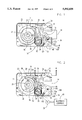
- FIGS. 1 illustrates the elements of the bolt withdrawal mechanism and interlock in the locked state, as viewed from the rear of the mechanism.
- FIG. 2 illustrates the elements of the bolt withdrawal mechanism and interlock in the unlocked state, as viewed from the rear of the mechanism.
- FIG. 3 illustrates the elements of the bolt withdrawal mechanism and interlock in the unlocked state as viewed from the front of the mechanism.
- FIG. 4 illustrates the thermal protection and relock mechanism for the lock where an interlock disables the lock operability after a threshold temperature is exceeded or where the cover of the lock is displaced, in a sectional view along line 4--4 in FIG. 2.
- FIG. 5 is an exploded frontal view of the anti-impact interlock parts of the lock.
- FIG. 6 is an illustration of the lock housing cover with an interlock retaining pin projecting therefrom.
- the lock 10 has a lock housing 12 which encloses the mechanism for moving the bolt 14 from an extended to a retracted position and returning the bolt 14 to an extended position.
- Bolt 14 is mounted for sliding movement within housing 12. Movement of the bolt 14 is provided by pawl 16 which is connected by screw 18 to the bolt 14. Pawl 16 is formed to include pawl tip 20 which projects from pawl 16 to be engaged by wheel 22. Wheel 22 is a composite of several components to provide several functions. Interior gear teeth 24 are provided to mesh with and drive a geared input to a stepper motor 38, not shown, which electrically powers the electronic controls of the lock 10.
- Wheel 22 is provided with a raised structure 26, projecting from the plane of the wheel 22 and having a partially cylindrical shape. The portion of the cylinder which remains terminates in two surfaces 28, 30 which function to deliver forces to pawl tip 20 in order to drive the pawl 16 to further move the bolt 14.
- Surface 30 is a restore cam surface. When the wheel 22 is reversed and the pawl 16 is in the position shown in FIG. 2, the pawl tip 20 is pushed by cam surface 30 to force the pawl 16 and bolt 14 to the right and thus extend the bolt 14.
- FIG. 1 illustrates pawl 16 occupying the locked position.
- the tip 20 is withdrawn from the rotational path of surfaces 28 or 30.
- Wheel 22 will rotate with the dial, not shown, and dial shaft 32 to provide electrical power to the lock 10 and to input the combination as described in co-pending application Ser. No. 07/719,046, filed Jun. 21, 1991, by Gerald L. Dawson, et al., and commonly assigned with this application and now abandoned.
- Wheel 22 is provided with teeth 36 which will mesh with gear 34 when gear 34 is rotated into meshing relation with teeth 36 by stepper motor 38.
- Gear 34 has a segment removed to form a relieved region 35. When the lock 10 is in a locked state and all the parts are in their respective restored positions, the relieved portion 35 faces the periphery of wheel 22, permitting free rotation of wheel 22, and complete disconnection of the gear teeth on wheel 22 from the teeth on gear 34.
- Rotation of gear 34 is accomplished by a small low voltage, low current stepper motor 38 which is activated by the electronic controls 40 of the lock 10.
- the rotation of the gear 34 is relatively uninhibited by outside forces such as friction or mechanical load, because the connection to cam 42 is through lost motion slots 44 and pins 46 residing on cam 42.
- the gear 34 is unimpeded in rotation until the ends of the lost motion slots 44 engage pins 46. This occurs only after the rotation by the stepper motor 38 is completed.
- Interposer slide 48 is slideably mounted in the lock housing 12 and permitted to move relative to the housing 12.
- the interposer slide 48 is provided with four engagement surfaces. The first of these engagement surfaces is a follower pin 92 shown in FIG. 5.
- follower pin 92 is engageable by cam surface 41 on cam 42. As cam 42 is rotated, surface 41 will rotate about axis 58 and contact follower pin 92. With continued rotation of cam 42, surface 41 will act on follower pin 90 to pull interposer slide downward against the force of restore springs 60.
- the second engagement surface of interposer slide 48 is slot 62.
- Slot 62 engages with pin 64 found on the pawl 16.
- pin 64 is pulled downward and rotates pawl 16 around the axis of screw 18 in a counter-clockwise direction, as viewed in FIGS. 1 and 2, and in a clockwise direction as viewed in FIGS. 3 and 5.
- Movement of pin 64 by surface 62 presents pawl tip 20 to surface 28 as wheel 22 is rotated.
- the third engagement surface of the interposer slide 48 is latch surface 66.
- Latch surface 66 permits latching the interposer 48 in the restored position to prevent the lock from opening under two different types of attack.
- the latch mechanism 70 for accomplishing this latching function is shown in FIG. 4.
- Latch mechanism 70 combines two forms of protection against attack on the lock 10, utilizing latch surface 66 and latch arm 78. Typical security specifications for locks of this type and level of protection provide that the lock must be rendered inoperative if the back plate of the lock housing 12 is displaced more than 0.1 inches (2.54 mm.) from the housing. Thus, instruments or devices may not be inserted into the lock housing to manipulate or position elements of the lock mechanism.
- the security specifications further require that the lock be rendered inoperative if the lock temperature exceeds a predetermined temperature, 75.6 degrees C. (168 degrees F.). Engagement surface 66 will be blocked from movement if the temperature of the lock 10 exceeds 70 degrees C. threshold temperature.
- Spring 72 is seated in the lock housing 12 and biases follower 74 upward against arm 78 of lever 76, urging arm 78 in a counter-clockwise direction.
- Arm 80 of lever 76 is engaged by plunger 82 which resides in an opening 84 in housing 12.
- the plunger 84 is held in a displaced position, as illustrated in FIG. 4, by the cover plate 88.
- a eutectic plug 86 Within a recess in cover plate 88 is a eutectic plug 86.
- Eutectic plug 86 is an alloy of metals that has a precise melting point, for example, 75.6 degrees C. Plug 86 will displace plunger 82 when the cover 88 is assembled to the lock housing 12.
- the displacement of plunger 82 results in rotation of arm 78 out of a position of interference with surface 66 of interposer slide 48 and arm 80 being held in the displaced position.
- the fourth engaging surface of the interposer slide is surface 90, best seen in FIG. 5.
- Surface 90 is the upper surface of the opening which forms surface 54.
- Pin 56 will engage the surface 90 if the interposer slide 48 is caused to displace downward against the forces of the restore springs 60, while lock 10 is locked, without the rotation of cam 42. This condition would exist when interposer slide 48 is moved but the stepper motor 38 is not energized to permit the unlocking of lock 10.
- stepper motor 38 When a drive signal is received by the stepper motor 38 from the electronic controls 40 indicating that the lock 10 is to open, the stepper motor 38 rotates gear 34 a partial revolution and presents the teeth of gear 34 to the teeth 36 of wheel 22. Rotation of wheel 22 by dial shaft 32 then will rotate gear 34 and reduce any play in the lost motion slots 44 to engage the lost motion slots 44 of gear 34 with pins 46 on cam 42. Further rotation of dial shaft 32 then will rotate cam 42 until it pulls interposer slide 48 downward by the action of cam 42 on follower pin 92. The downward motion of interposer slide 48 displaces pawl 16 presenting pawl tip 20 to surface 28 and permit still further rotation of wheel 22, thereby pulling on pawl tip 20 to translate bolt 14 to its withdrawn position.
- the pin 56 on cam 42 is positioned closely to surface 90. Should the enclosure be raised from the floor and then dropped, upon impact of the enclosure with the floor, the inertia of the pawl 16 and interposer 48 displace pawl 16 and interposer 48 downward relative to the lock housing 12. Pin 56 will then engage surface 90 to block further movement of interposer 48, causing a block restricting further movement of pawl 16.
- the lock 10 may not be defeated by impacting the enclosure with a significant force, such as dropping the enclosure on a floor or solid surface and rotating the dial shaft 32 very quickly after impact in the hope of catching pawl tip 20 on surface 28 and pulling pawl 16 toward an unlocked position past stop 17.
- the interlock system addresses three different modes of attack on the lock 10; it prevents both impact and thermal attack from being successful, as well as it displaces the lock housing back plate 88 to gain access to the lock works and any successful repositioning of the lock works elements.
- a relock interlock is actuatable to permanently block the bolt 14 in an extended position.
- the bolt 14 is provided with a recess 100 oriented so that the recess axis lies in a plane parallel with the largest plane surfaces of the bolt 14 and lying at an angle to the axis of movement of the bolt 14.
- the lock housing 12 is provided with a bore 102 or channel 102 formed or drilled therein at the same orientation as the recess 100 in the bolt 14.
- Within the bore 102 is positioned a plunger 104 with a rounded nose 106.
- the plunger 104 is biased by a spring 108 in compression, positioned behind the plunger 104.
- a threaded plug 110 is inserted into the bore and tightened to retain the spring in compression against the plunger 104.
- a hole 112 is drilled or formed into the lock housing 12, perpendicular to and intersecting at least a portion of the bore 102, to receive a pin.
- the cover plate 88 is provided with a pin 114, best seen in FIG. 6, positioned on the cover plate 88 to fit into the hole 112 when the cover plate 88 is assembled to the lock body 12.
- the pin 114 is long enough to extend to at least the intersection of the bore 102 and the hole 112, thereby protruding at least partially into the bore 102.
- the pin 114 extending into the bore will block the movement of the plunger 104 along the bore 102 and into the recess 100 in the bolt 14.
- the pin length may be tailored to any length that will release the plunger 104 upon any given amount of back plate 88 displacement from the lock housing 12.
- the components of movement of the plunger 104 are perpendicular to and parallel to the axis of movement of the bolt 14.
- the component of movement which is parallel to the axis of the bolt movement is in the direction of the bolt movement when translating to the extended bolt position.
- plunger 104 must be sheared to permit the movement of the bolt 14. The angular orientation of the plunger 104 insures that the attempted movement of the bolt 14 will bind the plunger 104, rather than urge it against the spring 108.
- the lock 10 must be disassembled in order to restore the plunger 104 to the retracted, ineffective position. Accordingly, the displacement of the cover plate 88 will activate both the blocking member 78 and the plunger 104 but the reassembly of the cover plate 88 will not restore the plunger 104 as it will the blocking member 78.
Landscapes
- Physics & Mathematics (AREA)
- General Physics & Mathematics (AREA)
- Casings For Electric Apparatus (AREA)
Abstract
Description
Claims (15)
Priority Applications (1)
| Application Number | Priority Date | Filing Date | Title |
|---|---|---|---|
| US07/839,174 US5592838A (en) | 1992-02-20 | 1992-02-20 | Anti-attack interlocks for a combination lock mechanism |
Applications Claiming Priority (1)
| Application Number | Priority Date | Filing Date | Title |
|---|---|---|---|
| US07/839,174 US5592838A (en) | 1992-02-20 | 1992-02-20 | Anti-attack interlocks for a combination lock mechanism |
Publications (1)
| Publication Number | Publication Date |
|---|---|
| US5592838A true US5592838A (en) | 1997-01-14 |
Family
ID=25279047
Family Applications (1)
| Application Number | Title | Priority Date | Filing Date |
|---|---|---|---|
| US07/839,174 Expired - Lifetime US5592838A (en) | 1992-02-20 | 1992-02-20 | Anti-attack interlocks for a combination lock mechanism |
Country Status (1)
| Country | Link |
|---|---|
| US (1) | US5592838A (en) |
Cited By (26)
| Publication number | Priority date | Publication date | Assignee | Title |
|---|---|---|---|---|
| US5775142A (en) * | 1996-12-03 | 1998-07-07 | Kim; Jitae | Electronic door lock |
| US5862692A (en) * | 1996-10-11 | 1999-01-26 | C.L. Industries, Inc. | Safe door lock with servo motor operated cam |
| US5881589A (en) * | 1997-06-12 | 1999-03-16 | Mas-Hamilton Group | Gear driven bolt withdrawal for an electronic combination lock |
| US5893283A (en) * | 1997-05-07 | 1999-04-13 | Mas-Hamilton Group | Solenoid controlled bolt control for an electronic lock |
| US6016677A (en) * | 1998-01-02 | 2000-01-25 | Sargent & Greenleaf, Inc. | Dead bolt combination lock and push-pull lock, each with integrated re-locking features, lock with auxiliary security features, and lock keypad with tamper detection and response features |
| US6038897A (en) * | 1998-09-18 | 2000-03-21 | Mas-Hamilton Group, Inc. | Back cover lock for a combination lock |
| US6094953A (en) * | 1998-11-10 | 2000-08-01 | Mas-Hamilton Group, Inc. | Electrically controlled slidebolt lock |
| US6098433A (en) * | 1998-04-02 | 2000-08-08 | American Security Products Company | Lock for safes and other security devices |
| WO2000068534A3 (en) * | 1999-05-06 | 2001-03-08 | Ilco Unican Inc | Electromechanical lock |
| US6434987B1 (en) * | 1999-07-12 | 2002-08-20 | Ilco-Unican S.A./ Relhor Division | Motorized security locking system |
| US6904778B2 (en) | 2003-04-28 | 2005-06-14 | Lockmasters, Inc. | Mechanical combination lock |
| US20060005592A1 (en) * | 2004-07-07 | 2006-01-12 | Moon Charles W | Manipulation-resistant combination lock |
| US20090115196A1 (en) * | 2007-10-13 | 2009-05-07 | Southco, Inc. | Latch actuator and latch using same |
| WO2011126514A1 (en) * | 2010-04-09 | 2011-10-13 | Kaba Mas, Llc | Relocking mechanism |
| US20120144884A1 (en) * | 2010-12-08 | 2012-06-14 | Michael J. Walsh & Associates, Inc. | Resistant mechanical combination lock and improvements thereto |
| US20130033045A1 (en) * | 2010-04-07 | 2013-02-07 | Sargent And Greenleaf, Inc | Shock resistant lock |
| US8667821B2 (en) | 2010-12-08 | 2014-03-11 | Michael J. Walsh & Associates, Inc. | Resistant mechanical combination lock and improvements thereto |
| US20140109632A1 (en) * | 2010-08-05 | 2014-04-24 | George Marshall Horne | High security lock |
| US20140165678A1 (en) * | 2012-12-19 | 2014-06-19 | Lock Ii, Llc | Device and methods for preventing unwanted access to a locked enclosure |
| EP2331780A4 (en) * | 2008-09-05 | 2014-12-31 | Lock Ii L L C | HIGH SECURITY LOCK |
| US20150225983A1 (en) * | 2012-09-04 | 2015-08-13 | Moving Magnet Technologies (Mmt) | Shock-resistant motorized locking device |
| US20170051532A1 (en) * | 2014-04-29 | 2017-02-23 | Hao Min | Electronic-mechanical dual control lock |
| US20170122008A1 (en) * | 2014-05-19 | 2017-05-04 | Hao Min | Safety locking mechanism for lockset |
| US9970215B2 (en) * | 2015-04-30 | 2018-05-15 | Bryan Michael Risi | Actuating assembly for a latching system |
| US10006230B2 (en) * | 2014-10-17 | 2018-06-26 | Hyundai Motor Company | Actuator integrated push opener |
| US10829881B2 (en) * | 2015-11-23 | 2020-11-10 | Scd Co., Ltd. | Door lock device for washing machine and method of locking washing machine door |
Citations (20)
| Publication number | Priority date | Publication date | Assignee | Title |
|---|---|---|---|---|
| US686073A (en) * | 1901-03-20 | 1901-11-05 | William H Hollar | Electrically-controlled combination-lock. |
| US2575674A (en) * | 1949-03-26 | 1951-11-20 | Harry C Miller | Permutation lock |
| US2807954A (en) * | 1954-07-06 | 1957-10-01 | Harry C Miller | Combination lock |
| GB815654A (en) * | 1956-05-04 | 1959-07-01 | Chubb & Sons Lock & Safe Co | Improvements in and relating to permutation locks |
| US3705739A (en) * | 1971-07-07 | 1972-12-12 | Ilco Corp | Panic lock device |
| US3811717A (en) * | 1973-03-01 | 1974-05-21 | Sargent & Co | Latch bolt stop lever for fire door lock sets |
| US3906761A (en) * | 1974-08-26 | 1975-09-23 | Frank H Swaim | Disabling mechanism for a combination lock |
| US4106316A (en) * | 1976-03-11 | 1978-08-15 | Chubb & Son's Lock And Safe Company Limited | Keyless combination locks |
| FR2447439A1 (en) * | 1979-01-26 | 1980-08-22 | Securite Incendie Montage | Lock for lever under constant recall force - has manual or thermal fuse release incorporating spring mounted release lever |
| US4222251A (en) * | 1978-09-08 | 1980-09-16 | Klaus W. Gartner | Additional locking system for combination lock |
| US4532785A (en) * | 1983-05-19 | 1985-08-06 | La Gard, Inc. | Combination lock |
| US4671087A (en) * | 1984-08-01 | 1987-06-09 | Wso Cpu-System Ab | Door lock including electrically actuable coupling arrangement |
| US4831851A (en) * | 1986-04-10 | 1989-05-23 | Supra Products, Inc. | Combination/electronic lock system |
| US4904984A (en) * | 1988-06-10 | 1990-02-27 | Gartner Klaus W | Combination lock with an additional security lock |
| US4967577A (en) * | 1988-06-10 | 1990-11-06 | La Gard, Inc. | Electronic lock with manual combination override |
| US5121950A (en) * | 1991-04-23 | 1992-06-16 | The Stanley Works | Heat activated spring loaded locking bolt for hinged doors and door assemblies employing same |
| US5257519A (en) * | 1992-04-13 | 1993-11-02 | Miller Iii J Clayton | Dead bolt assembly for combination dial lock assembly |
| US5271253A (en) * | 1992-03-16 | 1993-12-21 | Mas-Hamilton Group | Electronic combination lock with magnetic anti-attack interlock |
| US5307656A (en) * | 1990-12-17 | 1994-05-03 | La Gard, Inc. | High security electronic dial combination lock |
| US5487290A (en) * | 1992-01-13 | 1996-01-30 | C & M Technology, Inc. | High security lock mechanism |
-
1992
- 1992-02-20 US US07/839,174 patent/US5592838A/en not_active Expired - Lifetime
Patent Citations (20)
| Publication number | Priority date | Publication date | Assignee | Title |
|---|---|---|---|---|
| US686073A (en) * | 1901-03-20 | 1901-11-05 | William H Hollar | Electrically-controlled combination-lock. |
| US2575674A (en) * | 1949-03-26 | 1951-11-20 | Harry C Miller | Permutation lock |
| US2807954A (en) * | 1954-07-06 | 1957-10-01 | Harry C Miller | Combination lock |
| GB815654A (en) * | 1956-05-04 | 1959-07-01 | Chubb & Sons Lock & Safe Co | Improvements in and relating to permutation locks |
| US3705739A (en) * | 1971-07-07 | 1972-12-12 | Ilco Corp | Panic lock device |
| US3811717A (en) * | 1973-03-01 | 1974-05-21 | Sargent & Co | Latch bolt stop lever for fire door lock sets |
| US3906761A (en) * | 1974-08-26 | 1975-09-23 | Frank H Swaim | Disabling mechanism for a combination lock |
| US4106316A (en) * | 1976-03-11 | 1978-08-15 | Chubb & Son's Lock And Safe Company Limited | Keyless combination locks |
| US4222251A (en) * | 1978-09-08 | 1980-09-16 | Klaus W. Gartner | Additional locking system for combination lock |
| FR2447439A1 (en) * | 1979-01-26 | 1980-08-22 | Securite Incendie Montage | Lock for lever under constant recall force - has manual or thermal fuse release incorporating spring mounted release lever |
| US4532785A (en) * | 1983-05-19 | 1985-08-06 | La Gard, Inc. | Combination lock |
| US4671087A (en) * | 1984-08-01 | 1987-06-09 | Wso Cpu-System Ab | Door lock including electrically actuable coupling arrangement |
| US4831851A (en) * | 1986-04-10 | 1989-05-23 | Supra Products, Inc. | Combination/electronic lock system |
| US4904984A (en) * | 1988-06-10 | 1990-02-27 | Gartner Klaus W | Combination lock with an additional security lock |
| US4967577A (en) * | 1988-06-10 | 1990-11-06 | La Gard, Inc. | Electronic lock with manual combination override |
| US5307656A (en) * | 1990-12-17 | 1994-05-03 | La Gard, Inc. | High security electronic dial combination lock |
| US5121950A (en) * | 1991-04-23 | 1992-06-16 | The Stanley Works | Heat activated spring loaded locking bolt for hinged doors and door assemblies employing same |
| US5487290A (en) * | 1992-01-13 | 1996-01-30 | C & M Technology, Inc. | High security lock mechanism |
| US5271253A (en) * | 1992-03-16 | 1993-12-21 | Mas-Hamilton Group | Electronic combination lock with magnetic anti-attack interlock |
| US5257519A (en) * | 1992-04-13 | 1993-11-02 | Miller Iii J Clayton | Dead bolt assembly for combination dial lock assembly |
Non-Patent Citations (1)
| Title |
|---|
| English Translation of Germany 3,817,696. * |
Cited By (48)
| Publication number | Priority date | Publication date | Assignee | Title |
|---|---|---|---|---|
| US5862692A (en) * | 1996-10-11 | 1999-01-26 | C.L. Industries, Inc. | Safe door lock with servo motor operated cam |
| WO1999043913A1 (en) * | 1996-10-11 | 1999-09-02 | C.L. Industries Inc. | Safe door lock with servo motor operated cam |
| US5775142A (en) * | 1996-12-03 | 1998-07-07 | Kim; Jitae | Electronic door lock |
| EP0882860A3 (en) * | 1997-05-07 | 2000-09-13 | Mas-Hamilton Group | Solenoid controlled bolt control for an electronic lock |
| US5893283A (en) * | 1997-05-07 | 1999-04-13 | Mas-Hamilton Group | Solenoid controlled bolt control for an electronic lock |
| US5881589A (en) * | 1997-06-12 | 1999-03-16 | Mas-Hamilton Group | Gear driven bolt withdrawal for an electronic combination lock |
| US6016677A (en) * | 1998-01-02 | 2000-01-25 | Sargent & Greenleaf, Inc. | Dead bolt combination lock and push-pull lock, each with integrated re-locking features, lock with auxiliary security features, and lock keypad with tamper detection and response features |
| US6212923B1 (en) * | 1998-01-02 | 2001-04-10 | Sargent & Greenleaf, Inc. | Lock including means for sensing position of bolt and for indicating whether or not bolt is extended from lock case |
| US6098433A (en) * | 1998-04-02 | 2000-08-08 | American Security Products Company | Lock for safes and other security devices |
| WO2000017474A1 (en) * | 1998-09-18 | 2000-03-30 | Mas-Hamilton Group, Inc. | Back cover lock for a combination lock |
| US6038897A (en) * | 1998-09-18 | 2000-03-21 | Mas-Hamilton Group, Inc. | Back cover lock for a combination lock |
| US6094953A (en) * | 1998-11-10 | 2000-08-01 | Mas-Hamilton Group, Inc. | Electrically controlled slidebolt lock |
| WO2000068534A3 (en) * | 1999-05-06 | 2001-03-08 | Ilco Unican Inc | Electromechanical lock |
| US6434987B1 (en) * | 1999-07-12 | 2002-08-20 | Ilco-Unican S.A./ Relhor Division | Motorized security locking system |
| US6904778B2 (en) | 2003-04-28 | 2005-06-14 | Lockmasters, Inc. | Mechanical combination lock |
| US20060005592A1 (en) * | 2004-07-07 | 2006-01-12 | Moon Charles W | Manipulation-resistant combination lock |
| US20090115196A1 (en) * | 2007-10-13 | 2009-05-07 | Southco, Inc. | Latch actuator and latch using same |
| US8770633B2 (en) * | 2007-10-13 | 2014-07-08 | Southco, Inc. | Latch actuator and latch using same |
| EP3418477A1 (en) * | 2008-09-05 | 2018-12-26 | Lock II, L.L.C. | High security lock |
| EP2331780A4 (en) * | 2008-09-05 | 2014-12-31 | Lock Ii L L C | HIGH SECURITY LOCK |
| US9845618B2 (en) * | 2010-04-07 | 2017-12-19 | Sargent & Greenleaf, Inc. | Shock resistant lock |
| US20130033045A1 (en) * | 2010-04-07 | 2013-02-07 | Sargent And Greenleaf, Inc | Shock resistant lock |
| WO2011126514A1 (en) * | 2010-04-09 | 2011-10-13 | Kaba Mas, Llc | Relocking mechanism |
| US8826709B2 (en) | 2010-04-09 | 2014-09-09 | Kaba Mas, Llc | Relocking mechanism |
| CN102844509A (en) * | 2010-04-09 | 2012-12-26 | 卡巴麦斯有限公司 | Relocking mechanism |
| CN102844509B (en) * | 2010-04-09 | 2015-10-07 | 卡巴麦斯有限公司 | Latch mechanism again |
| US20140109632A1 (en) * | 2010-08-05 | 2014-04-24 | George Marshall Horne | High security lock |
| US8667821B2 (en) | 2010-12-08 | 2014-03-11 | Michael J. Walsh & Associates, Inc. | Resistant mechanical combination lock and improvements thereto |
| US20120144884A1 (en) * | 2010-12-08 | 2012-06-14 | Michael J. Walsh & Associates, Inc. | Resistant mechanical combination lock and improvements thereto |
| US8443639B2 (en) * | 2010-12-08 | 2013-05-21 | Michael J. Walsh & Associates, Inc. | Resistant mechanical combination lock and improvements thereto |
| US10550603B2 (en) * | 2012-09-04 | 2020-02-04 | Cogelec | Shock-resistant motorized locking device |
| US20150225983A1 (en) * | 2012-09-04 | 2015-08-13 | Moving Magnet Technologies (Mmt) | Shock-resistant motorized locking device |
| US10550604B2 (en) | 2012-12-19 | 2020-02-04 | Lock Ii, Llc | Device and methods for preventing unwanted access to a locked enclosure |
| US20140165678A1 (en) * | 2012-12-19 | 2014-06-19 | Lock Ii, Llc | Device and methods for preventing unwanted access to a locked enclosure |
| US12331551B2 (en) | 2012-12-19 | 2025-06-17 | Lock Ii, Llc | Device and methods for preventing unwanted access to a locked enclosure |
| US11613911B2 (en) | 2012-12-19 | 2023-03-28 | Lock Ii, Llc | Device and methods for preventing unwanted access to a locked enclosure |
| US10190335B2 (en) | 2012-12-19 | 2019-01-29 | Lock Ii, Llc | Methods for preventing unwanted access to a locked enclosure |
| US11499342B2 (en) | 2012-12-19 | 2022-11-15 | Lock Ii, Llc | Device and methods for preventing unwanted access to a locked enclosure |
| US10557285B2 (en) | 2012-12-19 | 2020-02-11 | Lock Ii, Llc | Device and methods for preventing unwanted access to a locked enclosure |
| US9816294B2 (en) | 2012-12-19 | 2017-11-14 | Lock Ii, Llc | Device and methods for preventing unwanted access to a locked enclosure |
| US9080349B2 (en) * | 2012-12-19 | 2015-07-14 | Lock II, L.L.C. | Device and methods for preventing unwanted access to a locked enclosure |
| US20170051532A1 (en) * | 2014-04-29 | 2017-02-23 | Hao Min | Electronic-mechanical dual control lock |
| US9657500B2 (en) * | 2014-04-29 | 2017-05-23 | Nanjing Easthouse Electrical Co., Ltd. | Electronic-mechanical dual control lock |
| US9822555B2 (en) * | 2014-05-19 | 2017-11-21 | Najing Easthouse Electrical Co., Ltd. | Safety locking mechanism for lockset |
| US20170122008A1 (en) * | 2014-05-19 | 2017-05-04 | Hao Min | Safety locking mechanism for lockset |
| US10006230B2 (en) * | 2014-10-17 | 2018-06-26 | Hyundai Motor Company | Actuator integrated push opener |
| US9970215B2 (en) * | 2015-04-30 | 2018-05-15 | Bryan Michael Risi | Actuating assembly for a latching system |
| US10829881B2 (en) * | 2015-11-23 | 2020-11-10 | Scd Co., Ltd. | Door lock device for washing machine and method of locking washing machine door |
Similar Documents
| Publication | Publication Date | Title |
|---|---|---|
| US5592838A (en) | Anti-attack interlocks for a combination lock mechanism | |
| US5862692A (en) | Safe door lock with servo motor operated cam | |
| EP1473425B1 (en) | Electric drop bolt with slidable drive mechanism | |
| EP2912246B1 (en) | Improved rotary blocking device | |
| JPH06229155A (en) | Security lock mechanism | |
| EP1174570A1 (en) | Mortise lockset with internal clutch | |
| GB2280474A (en) | Locking system for doors | |
| EP1126105A2 (en) | Lock mechanism | |
| EP0378124A1 (en) | Spring-latch and bolt lock with emergency opening device | |
| GB2069589A (en) | Locking doors | |
| EP0900900A2 (en) | Deadbolt combination lock system | |
| US4493199A (en) | Universal boltworks mechanism for safe door | |
| US5651568A (en) | Privacy snib mechanism | |
| US5484177A (en) | Dual function lock mechanism | |
| CN212336953U (en) | Latch bolt mechanism of lock and lock | |
| GB2307270A (en) | A lock mechanism | |
| EP0087225B1 (en) | Locking mechanism for door of security enclosure | |
| US7339472B2 (en) | Self-adjusting cam assembly | |
| US4724691A (en) | Lock bolt mechanism | |
| AU785407B2 (en) | Improvements in locks | |
| EP0870888B1 (en) | External unit for door lock | |
| EP0229514A1 (en) | Lock bolts | |
| EP0018712A1 (en) | Bolt mechanism, and security enclosure having such a bolt mechanism | |
| GB2045337A (en) | Bolt Mechanisms | |
| CA1116955A (en) | Relocking device for safes and the like |
Legal Events
| Date | Code | Title | Description |
|---|---|---|---|
| AS | Assignment |
Owner name: MAS-HAMILTON GROUP A CORP. OF KENTUCKY, KENTUCKY Free format text: ASSIGNMENT OF ASSIGNORS INTEREST.;ASSIGNORS:CLARK, THOMAS R.;DAWSON, GERALD L.;SCHERER, PAUL T.;REEL/FRAME:006026/0398;SIGNING DATES FROM 19920219 TO 19920220 |
|
| AS | Assignment |
Owner name: STAR BANK, NATIONAL ASSOCIATION, OHIO Free format text: SECURITY AGREEMENT;ASSIGNOR:MAS-HAMILTON GROUP, INC.;REEL/FRAME:007558/0461 Effective date: 19950501 |
|
| STCF | Information on status: patent grant |
Free format text: PATENTED CASE |
|
| FPAY | Fee payment |
Year of fee payment: 4 |
|
| AS | Assignment |
Owner name: UBS, AG ZURICH, SWITZERLAND Free format text: SECURITY AGREEMENT;ASSIGNORS:KABA CORPORATION;KABA ILCO CORPORATION;KABA HIGH SECURITY LOCKS CORPORATION;AND OTHERS;REEL/FRAME:012495/0716 Effective date: 20011001 |
|
| FPAY | Fee payment |
Year of fee payment: 8 |
|
| AS | Assignment |
Owner name: KABA CORPORATION, CONNECTICUT Free format text: RELEASE AND TERMINATION;ASSIGNOR:UBS AG, ZURICH;REEL/FRAME:015980/0516 Effective date: 20041102 Owner name: KABA ILCO CORPORATION, NORTH CAROLINA Free format text: RELEASE AND TERMINATION;ASSIGNOR:UBS AG, ZURICH;REEL/FRAME:015980/0516 Effective date: 20041102 Owner name: KABA HIGH SECURITY LOCKS CORPORATION, NORTH CAROLI Free format text: RELEASE AND TERMINATION;ASSIGNOR:UBS AG, ZURICH;REEL/FRAME:015980/0516 Effective date: 20041102 Owner name: ILCO UNICAN PROPERTIES, INC., NORTH CAROLINA Free format text: RELEASE AND TERMINATION;ASSIGNOR:UBS AG, ZURICH;REEL/FRAME:015980/0516 Effective date: 20041102 Owner name: KABA MAS CORPORATION, KENTUCKY Free format text: RELEASE AND TERMINATION;ASSIGNOR:UBS AG, ZURICH;REEL/FRAME:015980/0516 Effective date: 20041102 Owner name: KABA BENZING AMERICA, INC., FLORIDA Free format text: RELEASE AND TERMINATION;ASSIGNOR:UBS AG, ZURICH;REEL/FRAME:015980/0516 Effective date: 20041102 |
|
| FPAY | Fee payment |
Year of fee payment: 12 |