US5579918A - Material handling container - Google Patents
Material handling container Download PDFInfo
- Publication number
- US5579918A US5579918A US08/354,661 US35466194A US5579918A US 5579918 A US5579918 A US 5579918A US 35466194 A US35466194 A US 35466194A US 5579918 A US5579918 A US 5579918A
- Authority
- US
- United States
- Prior art keywords
- base
- base member
- slot
- foot
- end plate
- Prior art date
- Legal status (The legal status is an assumption and is not a legal conclusion. Google has not performed a legal analysis and makes no representation as to the accuracy of the status listed.)
- Expired - Fee Related
Links
Images


Classifications
-
- B—PERFORMING OPERATIONS; TRANSPORTING
- B65—CONVEYING; PACKING; STORING; HANDLING THIN OR FILAMENTARY MATERIAL
- B65D—CONTAINERS FOR STORAGE OR TRANSPORT OF ARTICLES OR MATERIALS, e.g. BAGS, BARRELS, BOTTLES, BOXES, CANS, CARTONS, CRATES, DRUMS, JARS, TANKS, HOPPERS, FORWARDING CONTAINERS; ACCESSORIES, CLOSURES, OR FITTINGS THEREFOR; PACKAGING ELEMENTS; PACKAGES
- B65D85/00—Containers, packaging elements or packages, specially adapted for particular articles or materials
- B65D85/66—Containers, packaging elements or packages, specially adapted for particular articles or materials for jumbo rolls; for rolls of floor covering
-
- B—PERFORMING OPERATIONS; TRANSPORTING
- B65—CONVEYING; PACKING; STORING; HANDLING THIN OR FILAMENTARY MATERIAL
- B65D—CONTAINERS FOR STORAGE OR TRANSPORT OF ARTICLES OR MATERIALS, e.g. BAGS, BARRELS, BOTTLES, BOXES, CANS, CARTONS, CRATES, DRUMS, JARS, TANKS, HOPPERS, FORWARDING CONTAINERS; ACCESSORIES, CLOSURES, OR FITTINGS THEREFOR; PACKAGING ELEMENTS; PACKAGES
- B65D21/00—Nestable, stackable or joinable containers; Containers of variable capacity
- B65D21/08—Containers of variable capacity
Definitions
- This invention relates to a material handling container for shipping and storing manufactured products, and more particularly to a material handling container for storing and shipping rolls of wound fabric or sheets of thin film which are shipped using elongated cores.
- the elongated rolls are shipped on pallets having fixed lengths and widths.
- the rolls are positioned in end plates having a central portion for receiving the elongated rolls.
- the end plates are then are placed on the pallets and secured in place.
- different sizes of pallets are used to ship the rolls and a large quantity of different size pallets are kept in inventory.
- U.S. Pat. No. 4,151,914 discloses a shipping and storage container having an open top box structure comprised of blanks which have score lines for folding which may be stapled to one another to define a box of various lengths and widths.
- the box components are stapled, the box still requires a pallet to be used for handling and transfer of the loaded container. Accordingly, many different size pallets will be required to ship rolls of various lengths.
- U.S. Pat. No. 4,042,107 discloses a rigid shipping container for elongated rolls.
- the rigid shipping container includes a plurality of spaced holes which receive pins connected with end plate assemblies. Accordingly, while the structure would accommodate rolls of different lengths, it is not flexible to accommodate rolls of different widths. Furthermore, the rigid nature of the structure provides for a waste of material when the rolls are greatly smaller than the size of the container.
- an object of the present invention to provide an adjustable shipping container which can ship cylindrical rolls of material of various lengths and widths;
- the above objectives are accomplished according to the present invention by providing an adjustable shipping and storage container for handling materials which may vary in length which can be manipulated by a fork lift.
- the container includes a base unit having a first and second base assembly each having a base member and at least one base floor support element member supporting a respectively base member on a floor. Each base floor support element defines a fork channel underneath the respective base member for receiving a fork of a fork lift enabling the shipping container to be manipulated by a fork lift.
- the second base assembly is independent from and generally parallel to the first base assembly providing the base unit with variable width capability.
- the shipping container includes a first and second mounting mechanism slidably carried by the base unit for adjusting the relative length of the base unit.
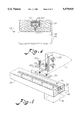
- FIG. 1 is a perspective view of a shipping and storage container according to the invention
- FIG. 2 is a cut-away view taken along line 2--2 of FIG. 1;
- FIG. 3 is perspective view of a stringer extension element according to the invention.
- FIG. 4 is a cut-way view taken along line 4--4 of FIG. 3;
- FIG. 5 is another embodiment of a variable length base element according to the invention.
- FIGS. 1, 2 and 3 illustrate an adjustable shipping and storage container A for handling a roll of material on an elongated core 8 (illustrated in dotted lines) which is handled by a standard fork lift having forks.
- Container A is comprised of an adjustable base unit B, a first end plate 10 defining a first end plate opening 11 for receiving a first end of elongated core 8 and a second end plate 12 defining a second end plate opening 13 for receiving a second end of the elongated core 8.
- side support stringers 14 and 16 interconnect end plates 10 and 12 along the sides of container A and a first top support stringer 18 and a second top support stringer 20 interconnect the two end plates along the top of container A.
- base unit B includes a first base assembly 22 which includes a first base member 24 and at least one first base floor support element 26 supporting first base member 24 on a floor.
- Second base assembly 28 includes a second base member 30 and at least one second base floor support element 32 supporting second base member 30 on a floor.
- Second base assembly 28 is separate and independent from first base assembly 22 and runs generally parallel to first base assembly 22. The independent relationship of second base assembly 28 with first base assembly 22 enables container A to be adjustable along its width.
- first and second base members are two by four stringers. Accordingly, to accommodate material for shipping having various outside diameters only end plates of various sizes are required to be interchanged while maintaining the same first and second base assemblies.
- first base floor support element 26 defines a first fork channel 34 underneath first base member 22 for receiving a first fork of a fork lift.
- second base floor support element 32 defines a second fork channel 36 underneath second base member 30 for receiving a second fork of a fork lift.
- first base floor support element 26 and second base floor support element 32 each respectively includes at least two support elements having a spacing less than the length of a fork of a fork lift for housing the forks.
- First and second base floor support elements are of a general U-shaped design which depend from first base member and second base member respectively. The U-shaped design defines the respective fork channel and also provides support for the first and second base members on a floor.
- first and second floor support elements provide an essential feature enabling container A to be handled from the side.
- first base member 24 slidably carries first stringer adjustment assembly 38 and second base member 30 slidably carries second stringer adjustment assembly 40.
- First stringer adjustment assembly 38 includes first foot element 42 having sleeve 44 and first foot floor support element 46 which further defines first fork channel 34.
- Sleeve 44 is of sufficient height and width to receive first base member 24.
- Sleeve 44 includes a hollow mouth 48 for receiving an end of first base member 24.
- Second stringer adjustment assembly 40 includes second foot element 50 having sleeve 52 and second foot floor support element 54 which further defines second fork channel 36.
- Sleeve 52 is of sufficient height and width to receive second base member 30.
- Sleeve 52 includes second base member mouth 56 for receiving an end of second base member 30.
- first base member 24 includes a first base slot 58 having a rail 60 and second base member 30 includes a second base slot 62 having a rail 64.
- Base slots 58 and 62 may be standard unitstruts. Slots 58 and 62 may be any length but in the preferred embodiment they are approximately 24 inches long.
- First foot element 42 having first guide pin hole 66 is slidably mounted with respect to first base member 24.
- First guide pin 68 which may be a screw is received within first guide pin hole 66 and first base slot 58.
- First guide pin 68 is slidably maintained within first base slot 58 by first guide lock 70 which may be a nut.
- Second foot element 50 is similarly carried by second base member 30.
- first base member 24 which includes first base slot 58 will be received within hollow mouth 48.
- First guide pin 68 is placed within first guide pin hole 66 and first guide lock 70 is secured to first guide pin 68.
- First base slot 58 is aligned with first guide lock 70 and first guide lock 70 is received by first base slot 58 below rail 60.
- first foot element 82 can freely move along first base slot 58.
- first guide lock 70 is a nut and first guide pin 68 is a screw for securing first foot element 42 in place.
- Second base member 30 and second foot element 50 are similarly attached as first base member 24 and first foot element 42.
- base unit B By providing base unit B with adjustability in both a longitudinal and latitudinal direction with the means for handling by a fork lift, base unit B may be used with any horizontal member such as a plywood board for supporting any material for shipping.
- base unit B is used for shipping rolls of material wound on an elongated core.
- First end plate 10 having a first end plate opening 11 receives a first end of core 8 and second end plate 12 having a second end plate opening 13 receives a second end of core 8.
- second end plate 12 is slidably attached to base unit B.
- first mounting mechanism 76 slidably carried by first base member 24.
- First mounting mechanism 76 includes first stringer adjustment assembly 38 and first foot mounting bracket 78 integral with first stringer adjustment assembly 38 on one end and carried by second end plate 12 at another end. In the first embodiment illustrated in FIG.
- first foot mounting bracket 78 is permanently attached to first foot element 42 and is temporarily affixed to second end plate 12 by bolts.
- Second end plate 12 is similarly attached to second base member 30 utilizing second mounting mechanism 80.
- Second mounting mechanism 80 includes second stringer adjustment assembly 40 slidably attached to second base member 30 and second foot mounting bracket 82.
- a first end of second foot mounting bracket 82 is attached to second end plate 12 and a second end of second foot mounting bracket 82 is attached to second foot element 50.
- second end plate 12 may be positioned at a desired distance apart from first end plate 10 to accommodate an elongated cylindrical core of a length within the range of base unit B in an extended and non-extended position.
- first side support stringer 14 has first side slot 86 and second side support stringer 16 has second side slot 88 which extend through the width of support stringers 14 and 16 respectively.
- First L-shaped side brace 90 is mounted on second end plate 12 having a hole (not shown) for receiving first side support bolt 92 which passes through first side slot 86 securing second end plate 12 with first side support stringer 14. Both first side slot 86 and second side slot 88 are respectively located on the ends of first side support stringer 14 and second side support stringer 16 which are above first foot element 42 and second foot element 50.
- First side slot 86 and second side slot 88 are of a length approximately equal to the length of first base slot 58 and second base extension slot 62 respectively enabling second end plate 12 to slide in relationship with first and second side support stringers 14 and 16 along a proportionate length as second end plate 12 slides with respect to base unit B.
- second end plate 12 may be secured with first end plate 10 at any length which base unit B can be adjusted.
- first top support stringer 18 and second top support stringer 20 include first top slot 98 and second top slot 100 which extend through the width of top support stringers 18 and 20 respectively.
- Third L-shaped side brace 102 is mounted on second end plate 12 having a hole (not shown) for receiving first top support bolt 104 which passes through first top slot 98 securing second end plate 12 with first top support stringer 18.
- Both first top slot 98 and second top slot 100 are respectively located on the ends of first top support stringer 18 and second top support stringer 20 which are above first foot element 42 and second foot element 50.
- First top slot 98 and second top slot 100 are of a length approximately equal to the length of first base slot 58 and second base slot 62 respectively enabling second end plate 12 to slide in relationship with first and second top support stringers 18 and 20 along a proportionate length as second end plate 12 slides with respect to base unit B.
- second end plate 12 may be secured with first end plate 10 at any length which base unit B can be adjusted.
- first base brace 110 connects first end plate 10 with second base member 30.
- a similar brace (not shown) attaches first end plate 10 with first base member 24.
- fifth L-shaped brace 112 attaches first end plate 10 with second side support stringer 16.
- a similar L-shaped brace (not shown) attaches first end plate 10 with first side support stringer 14.
- sixth L-shaped brace 114 attaches first end plate 10 with second top support stringer 18.
- a similar L-shaped brace (not shown) attaches first end plate 10 with first top support stringer 18. In this manner each of the supporting stringers i.e.
- first end plate 10 base, side and top, are secured on one side to first end plate 10 and slidably attached to second end plate 12 enabling second end plate 12 to be positioned at a desired distance apart from first end plate 10 according to the length of the elongated cylindrical roll being shipped or stored.
- first and second base members are flush with end plates 10 and 12. Accordingly, the space required to ship an elongated cylindrical roll of a given length is generally no more than the length of the roll with no excessive space being required by container A.
- FIG. 5 shows an alternative embodiment for slidably attaching second end plate 12 to base unit B.
- first mounting mechanism 116 includes first bracket assembly 130 slidably carried by first base member 24.
- the first end of first bracket assembly 130 includes first guide pin hole 118 which receives first guide pin 120 and second guide pin hole 122 which receives second guide pin 124.
- Both first and second guide pins 120 and 124 are preferably bolts.
- Lock 126 which is preferably a nut, is received within first base slot 58 and first and second guide pins 120 and 124 are secured to lock 126.
- the second end of first bracket assembly 130 is secured to second end plate 12 by bolts 128. Accordingly, in operation, second end plate 12 is slidably attached to first base member 24.
- First base slot 58 is aligned with lock 126 and first lock 126 is received by first base slot 58 below rail 60.
- first bracket assembly 130 can freely move along first base slot 58 thereby adjusting the relative length of first base member 24.
- first bracket assembly 130 is locked into place by tightening first and second guide pins 120 and 124 engaging lock 126 with rail 60.
- Second base member 30 and second end plate 12 are similarly slidably attached.
- a more advantageous container for shipping and storing elongated cylindrical rolls and the like may be had according to the invention.
- a container that is adjustable in a lateral and longitudinal direction cylindrical rolls of various lengths and outside diameter dimensions may be shipped utilizing a standard container.
- a flexible container By providing a flexible container, the need for a large inventory of fixed size pallets or other fixed sized shipping containers is eliminated enabling a manufacturing facility to operate with less containers and components in inventory reducing inventory costs.
Abstract
Description
Claims (15)
Priority Applications (1)
| Application Number | Priority Date | Filing Date | Title |
|---|---|---|---|
| US08/354,661 US5579918A (en) | 1994-12-14 | 1994-12-14 | Material handling container |
Applications Claiming Priority (1)
| Application Number | Priority Date | Filing Date | Title |
|---|---|---|---|
| US08/354,661 US5579918A (en) | 1994-12-14 | 1994-12-14 | Material handling container |
Publications (1)
| Publication Number | Publication Date |
|---|---|
| US5579918A true US5579918A (en) | 1996-12-03 |
Family
ID=23394389
Family Applications (1)
| Application Number | Title | Priority Date | Filing Date |
|---|---|---|---|
| US08/354,661 Expired - Fee Related US5579918A (en) | 1994-12-14 | 1994-12-14 | Material handling container |
Country Status (1)
| Country | Link |
|---|---|
| US (1) | US5579918A (en) |
Cited By (13)
| Publication number | Priority date | Publication date | Assignee | Title |
|---|---|---|---|---|
| DE19756623C1 (en) * | 1997-12-19 | 1999-04-22 | Joerg Fasbender | Assemblable, full or at least partly full-walled transport and storage container |
| US6073768A (en) * | 1998-05-18 | 2000-06-13 | Mitsubishi Polyester Film, Llc | Packaging system |
| US20010032900A1 (en) * | 2000-03-24 | 2001-10-25 | Rainer Buschulte | Apparatus for storing, transporting and delivering flat printing material for a machine processing such material |
| US20040029617A1 (en) * | 2002-08-08 | 2004-02-12 | Mpf Technologies, Inc. | Track system for telecommunications transmission stations |
| US20050167308A1 (en) * | 2004-02-04 | 2005-08-04 | Darby Robert J. | Palletless packaging system |
| GB2412907A (en) * | 2004-04-05 | 2005-10-12 | Chen Hsiu-Man Yu | A dispenser for carpet protective-film |
| WO2007094025A1 (en) * | 2006-02-15 | 2007-08-23 | Alessandro Petrillo | Variable volume container |
| US20090020045A1 (en) * | 2006-02-16 | 2009-01-22 | Schoeller Arca Systems Services Gmbh | Multiple-use transport unit for sheet-material rolls and the like |
| US8469191B2 (en) | 2010-10-27 | 2013-06-25 | Ashworth Bros., Inc. | Apparatus for storing, transporting and dispensing conveyor belts |
| US20140299706A1 (en) * | 2013-04-03 | 2014-10-09 | Joseph J. DiSabantonio, III | Stackable pallet system having foldable end boards |
| NO336340B1 (en) * | 2013-09-10 | 2015-08-03 | Vendor As | Device for transporting a positioning propeller |
| US9586721B2 (en) | 2014-08-21 | 2017-03-07 | Marshance Corporation | Adjustable suspended roll packaging system |
| US9908654B2 (en) | 2010-10-27 | 2018-03-06 | Ashworth Bros., Inc. | Apparatus for storing, transporting and dispensing conveyor belts |
Citations (6)
| Publication number | Priority date | Publication date | Assignee | Title |
|---|---|---|---|---|
| US3337036A (en) * | 1965-04-15 | 1967-08-22 | Thomas G Peterson | Disposable and collapsible storage and shipping container |
| US3502237A (en) * | 1968-03-25 | 1970-03-24 | Donald Verhein | Base for a collapsible container |
| US4042107A (en) * | 1975-02-24 | 1977-08-16 | Ici United States Inc. | Returnable roll shipping container |
| US4151914A (en) * | 1978-07-24 | 1979-05-01 | Franklin Container Corporation | Shipping and storage container for rolls |
| US4231475A (en) * | 1979-03-20 | 1980-11-04 | Timron, Inc. | Shipping carton for pile fabric and a machine for winding pile fabric on a reel |
| US4401217A (en) * | 1981-03-04 | 1983-08-30 | Franklin Container Corporation | Roll retainer |
-
1994
- 1994-12-14 US US08/354,661 patent/US5579918A/en not_active Expired - Fee Related
Patent Citations (6)
| Publication number | Priority date | Publication date | Assignee | Title |
|---|---|---|---|---|
| US3337036A (en) * | 1965-04-15 | 1967-08-22 | Thomas G Peterson | Disposable and collapsible storage and shipping container |
| US3502237A (en) * | 1968-03-25 | 1970-03-24 | Donald Verhein | Base for a collapsible container |
| US4042107A (en) * | 1975-02-24 | 1977-08-16 | Ici United States Inc. | Returnable roll shipping container |
| US4151914A (en) * | 1978-07-24 | 1979-05-01 | Franklin Container Corporation | Shipping and storage container for rolls |
| US4231475A (en) * | 1979-03-20 | 1980-11-04 | Timron, Inc. | Shipping carton for pile fabric and a machine for winding pile fabric on a reel |
| US4401217A (en) * | 1981-03-04 | 1983-08-30 | Franklin Container Corporation | Roll retainer |
Cited By (16)
| Publication number | Priority date | Publication date | Assignee | Title |
|---|---|---|---|---|
| DE19756623C1 (en) * | 1997-12-19 | 1999-04-22 | Joerg Fasbender | Assemblable, full or at least partly full-walled transport and storage container |
| US6073768A (en) * | 1998-05-18 | 2000-06-13 | Mitsubishi Polyester Film, Llc | Packaging system |
| US20010032900A1 (en) * | 2000-03-24 | 2001-10-25 | Rainer Buschulte | Apparatus for storing, transporting and delivering flat printing material for a machine processing such material |
| US6663041B2 (en) * | 2000-03-24 | 2003-12-16 | Heidelberger Druckmaschinen Ag | Apparatus for storing, transporting and delivering roll-formed flat printing material for a machine processing such material |
| US20040029617A1 (en) * | 2002-08-08 | 2004-02-12 | Mpf Technologies, Inc. | Track system for telecommunications transmission stations |
| US20050167308A1 (en) * | 2004-02-04 | 2005-08-04 | Darby Robert J. | Palletless packaging system |
| GB2412907A (en) * | 2004-04-05 | 2005-10-12 | Chen Hsiu-Man Yu | A dispenser for carpet protective-film |
| GB2412907B (en) * | 2004-04-05 | 2006-03-15 | Hsiu-Man Yu Chen | Carpet protective film packing device |
| WO2007094025A1 (en) * | 2006-02-15 | 2007-08-23 | Alessandro Petrillo | Variable volume container |
| US20090020045A1 (en) * | 2006-02-16 | 2009-01-22 | Schoeller Arca Systems Services Gmbh | Multiple-use transport unit for sheet-material rolls and the like |
| US8469191B2 (en) | 2010-10-27 | 2013-06-25 | Ashworth Bros., Inc. | Apparatus for storing, transporting and dispensing conveyor belts |
| US9908654B2 (en) | 2010-10-27 | 2018-03-06 | Ashworth Bros., Inc. | Apparatus for storing, transporting and dispensing conveyor belts |
| US20140299706A1 (en) * | 2013-04-03 | 2014-10-09 | Joseph J. DiSabantonio, III | Stackable pallet system having foldable end boards |
| NO336340B1 (en) * | 2013-09-10 | 2015-08-03 | Vendor As | Device for transporting a positioning propeller |
| US9586721B2 (en) | 2014-08-21 | 2017-03-07 | Marshance Corporation | Adjustable suspended roll packaging system |
| US9840363B2 (en) | 2014-08-21 | 2017-12-12 | Marshane Corp. | Adjustable suspended roll packaging system |
Similar Documents
| Publication | Publication Date | Title |
|---|---|---|
| US5579918A (en) | Material handling container | |
| US6422407B2 (en) | Article transporting/storing apparatus | |
| US7971733B2 (en) | Window pallet and method of use thereof | |
| US3165078A (en) | Pallet | |
| CA2102727C (en) | Paper pallet | |
| US2611569A (en) | Paperboard pallet | |
| US6354229B1 (en) | Shipping platform | |
| US3626860A (en) | Foldable expendable four-way entry pallet | |
| US5285731A (en) | Lightweight fiberboard pallet | |
| US4068599A (en) | Unitizing frame for a pallet | |
| JP4814222B2 (en) | platform | |
| US20080223262A1 (en) | Pallet With Foldable Platform Surface | |
| EP0662426A1 (en) | Folding crate for holding packages | |
| US5899337A (en) | Collapsible octagonal box for heavy load (5,000+ pounds) | |
| US3113532A (en) | Pallet | |
| KR101067255B1 (en) | A loading ledge | |
| US5690037A (en) | Lightweight foldable pallet and related lifting apparatus | |
| US20080190810A1 (en) | Collapsible Transport and Storage Container | |
| US4401217A (en) | Roll retainer | |
| US5517926A (en) | Collapsible pallet | |
| US11161644B2 (en) | Modular stackable merchandise trays | |
| US5755163A (en) | Cargo support unit | |
| US5275289A (en) | Frame container support and stackable container system using same | |
| US20050133659A1 (en) | End-board for a core-wound roll product packaging system | |
| US4220431A (en) | Apparatus for in field unitizing of containers |
Legal Events
| Date | Code | Title | Description |
|---|---|---|---|
| AS | Assignment |
Owner name: MARSHANE CORPORATION, SOUTH CAROLINA Free format text: ASSIGNMENT OF ASSIGNORS INTEREST;ASSIGNOR:MCCURRY, GREG;REEL/FRAME:007284/0074 Effective date: 19941201 |
|
| AS | Assignment |
Owner name: MCCURRY, GREG (50% OF ANY RIGHT, TITLE AND INTERES Free format text: CORRECTED ASSIGNMENT.;ASSIGNOR:MCCURRY, GREG;REEL/FRAME:007421/0024 Effective date: 19941201 Owner name: MARSHANE CORPORATION (50% OF ANY RIGHT, TITLE, AND Free format text: CORRECTED ASSIGNMENT.;ASSIGNOR:MCCURRY, GREG;REEL/FRAME:007421/0024 Effective date: 19941201 |
|
| FEPP | Fee payment procedure |
Free format text: PAYOR NUMBER ASSIGNED (ORIGINAL EVENT CODE: ASPN); ENTITY STATUS OF PATENT OWNER: SMALL ENTITY |
|
| REMI | Maintenance fee reminder mailed | ||
| LAPS | Lapse for failure to pay maintenance fees | ||
| FP | Lapsed due to failure to pay maintenance fee |
Effective date: 20001203 |
|
| STCH | Information on status: patent discontinuation |
Free format text: PATENT EXPIRED DUE TO NONPAYMENT OF MAINTENANCE FEES UNDER 37 CFR 1.362 |