US5561577A - ESD protection for IC's - Google Patents
ESD protection for IC's Download PDFInfo
- Publication number
- US5561577A US5561577A US08/190,756 US19075694A US5561577A US 5561577 A US5561577 A US 5561577A US 19075694 A US19075694 A US 19075694A US 5561577 A US5561577 A US 5561577A
- Authority
- US
- United States
- Prior art keywords
- integrated circuit
- scr
- trigger
- esd
- coupled
- Prior art date
- Legal status (The legal status is an assumption and is not a legal conclusion. Google has not performed a legal analysis and makes no representation as to the accuracy of the status listed.)
- Expired - Fee Related
Links
Images


Classifications
-
- H—ELECTRICITY
- H01—ELECTRIC ELEMENTS
- H01L—SEMICONDUCTOR DEVICES NOT COVERED BY CLASS H10
- H01L27/00—Devices consisting of a plurality of semiconductor or other solid-state components formed in or on a common substrate
- H01L27/02—Devices consisting of a plurality of semiconductor or other solid-state components formed in or on a common substrate including semiconductor components specially adapted for rectifying, oscillating, amplifying or switching and having at least one potential-jump barrier or surface barrier; including integrated passive circuit elements with at least one potential-jump barrier or surface barrier
- H01L27/0203—Particular design considerations for integrated circuits
- H01L27/0248—Particular design considerations for integrated circuits for electrical or thermal protection, e.g. electrostatic discharge [ESD] protection
- H01L27/0251—Particular design considerations for integrated circuits for electrical or thermal protection, e.g. electrostatic discharge [ESD] protection for MOS devices
- H01L27/0259—Particular design considerations for integrated circuits for electrical or thermal protection, e.g. electrostatic discharge [ESD] protection for MOS devices using bipolar transistors as protective elements
Definitions
- Electrostatic Discharge is a potent killer of integrated circuits (IC's), and especially of IC's using Metal Oxide Semiconductors (MOS).
- MOS Metal Oxide Semiconductors
- FIG. 1 the bonded-out pads of an IC chip are denoted by large black squares, next to which appear associated generalized signal names for the corresponding pins on the IC package, such as SIG 1 , SIG 2 , GND and V DD .
- the figure shows output driver transistors that are connected between an output pad and ground (GND); for the sake of brevity, no loads or pull-up transistors are shown connected between these output pads and the power supply V DD , although it will be understood that such elements are present. Also, no input pads and associated circuitry are shown, as it will be likewise understood that these structures are also present on most IC's. Inputs are generally inherently more easily protectable than outputs, since it is usually possible to isolate the associated transistor from the input pad by some resistance. Nevertheless, let it be appreciated that inputs also are further protectable by the teachings set out below. It may be the case that typically the incremental benefit of further protecting an input is somewhat less than for further protecting an output, with its necessarily exposed driver transistor. So, we illustrate with outputs, with the understanding that our teachings are applicable to inputs, as well.
- every pad of the IC chip except GND and V DD is provided with an ESD current path through, and with overvoltage protection with respect to, a common location. (That common location is GND, which is why it is one of the exceptions).
- GND common location
- the idea is that for an ESD event between any two pins on the IC package (GND and V DD excluded), the (electron or hole) current caused by an ESD event will travel from one of the pins toward GND, and away from GND toward the other pin.
- FIG. 1 is associated with an IC that has a core (substrate) 1 of p material, and MOS Field Effect Transistors (FET's) whose sources and drains are of n material.
- FET's MOS Field Effect Transistors
- This arrangement produces normally back biased parasitic diodes 2 and 3.
- parasitic diode 2 associated with each output FET, such as FET 4 for SIG 2 and FET 5 for SIG 1 ; these are represented by diodes 6 and 7, respectively.
- the protective SCR's 8 and 9 which are in parallel with output FET's 4 and 5, respectively.
- the particular diode 3 shown in FIG. 1 normally never carries any current (it is shunted by the substrate 1 and its connection to GND), and is henceforth ignored.
- GND ground
- GND ground
- the term GND is used herein to denote the electrically common point within the IC to which power supply return currents are routed and thence combined into one current that is returned to the power supply.
- GND is not the actual return side of the power supply itself.
- the IC is probably mounted on a printed circuit board, and the return currents for all of the appropriate circuits on the board are brought together.
- the return current for that board is then combined in a wiring harness or on a mother board with the return currents from other circuit boards; that point of combination may be called System GND (SGND).
- SGND System GND
- the actual point of return to the power supply is probably some significant physical distance away, and it and SGND may not be electrically equivalent to GND for any particular IC, owing to DC voltage drops and noise developed across the AC impedance of the return path.
- the substrate 1 an element or component that is connected to GND (and probably in lots of places, too), but that nevertheless is not itself GND. The reason is that while it may be a doped semiconductor whose extensive cross section makes it a relatively good conductor as semiconductors go, it is not a particularly good conductor in an absolute sense, say as is copper or aluminum.
- ESD event such as the particular one depicted in FIG. 1.
- the IC could be considered as lying unprotected on a table top, although that is not absolutely necessary.
- a source of negative charge 11 arcs to or is otherwise brought into contact with (zaps) the IC pin bonded to pad 12 for SIG 1 .
- a resulting (electron) current I IN travels inward toward GND and starts by going through the parasitic diode 7 associated with the transistor 5 that drives, or is connected to, the "start-from" pad 12.
- the anode of parasitic diode 7 is connected to GND.
- I IN becomes I OUT and the remainder of the path to the "going-to" pad 13 (and thence to destination 15) is through a protection SCR 14 associated therewith, and that is provided for just this purpose.
- the SCR 14 must be triggered by a voltage sensing circuit (not shown), of which there is one for each such protective SCR (e.g., 8, 9).
- spoke-hub-spoke The "spoke-hub-spoke" model described above can be examined for contact with positive charge on any single pin, as well as for negative charge on any single pin.
- the path of the ESD current (of either holes or electrons, as appropriate) through a spoke will be either through a forward biased parasitic diode or through a triggered overvoltage protection SCR.
- the current could go in toward the hub on a single spoke and out from the hub on several spokes. Likewise, it could go in on several spokes and out on just one, or it could go in on several and out on several. Also, the case of simple charge sharing must be remembered.
- V DD is generally not included in the protection scheme outlined thus far.
- parasitic diodes 10 will take care of static zaps of one polarity, while breakdown of those diodes is relied upon for zaps of the other polarity. Relying upon such breakdown is not foolproof, but in comparison, there is a difficulty in incorporating a triggered switch such as an SCR into overvoltage protection for V DD : once an SCR is triggered on the gate loses control and the SCR cannot be simply "turned off". The result could be very bad news indeed for an IC zapped on V DD while the power was on.
- FIG. 2 depicts an IC having a single DGND, an IC might have more than one dirty ground.
- a remaining return path could be simply ground (GND), or it might make more sense to dispense with the label "GND” and treat any remaining return path as yet another instance of a DGND i .
- GND i some or all of which might be "dirty" and some not.
- the labeling scheme chosen doesn't matter too much as long as it is not misleading. That is because when all is said and done, the various DGND's are simply separate return paths for selected circuits that terminate at their own pins, different from the pin for GND, and don't differ from GND in any significant internal detail, save one. That difference is that the meandering conductor that interconnects each of the circuit elements to be connected to GND is deposited directly onto the substrate, while conductors for dirty grounds are insulated from the substrate by an intervening glass layer (e.g., SiO 2 ). From the pins of the IC the various grounds are routed by low-valued ohmic connections to a common location on the return side of the power supply.
- an intervening glass layer e.g., SiO 2
- IC output signal pads 24 and 25 are driven by transistors 17 and 20, respectively.
- the power supply return for driver transistors 17 and 20 is provided by a pad 16 that is DGND.
- DGND a protective SCR 23 with anode connected to DGND and cathode connected to GND.
- Diodes 18 and 21 are each an instance of parasitic diode 26.
- Resistances 19 and 22 represent resistances from the anodes of those parasitic diodes, through the bulk of the substrate, to the GND pad 27. In general, resistances 19 and 22 are not equal, and as distributed entities, may partially overlap so that a voltage developed across one is in part communicated to the other.
- DGND is not a hub in the sense that GND is; rather, DGND is at a distal end of a spoke whose other end is GND.
- a solution to this problem is to equip each output structure (and input structures, too, if desired) with an additional protective SCR triggered with respect to the particular dirty ground servicing or associated that structure. It would also be advantageous if the additional SCR could be physically co-located with the conventional SCR referenced to GND. It will further be appreciated that the additional protective device need not necessarily be an SCR; other protective devices such as field oxide punch through devices, field emission devices, spark gaps, zeners and switched FET's could serve as the protective device. The important thing is that it would be connected between the pad whose transistors are to be protected and the associated dirty ground. Some further advantage may be gained by providing a protective device from other pads to DGND, even though the associated transistors for those pads are not served by DGND.
- the techniques described herein can be especially useful in qualifying an integrated circuit under MIL-SPEC 883. That standard requires that each pin of an integrated circuit be electrically stressed with respect to every other pin, using the Human Body Model (a source of charge comprising 100 pfd in series with 1.5 Kohm) charged to either two kilovolts, four kilovolts, or greater than four kilovolts, according to a class of compliance desired. Since DGND is one of those pins in a chip that uses a dirty ground, protecting all the other pins just with respect to GND alone does not necessarily provide adequate protection for electrical stress of those pins with respect to DGND.
- Human Body Model a source of charge comprising 100 pfd in series with 1.5 Kohm
- the preferred protective device is an SCR, which, of course, is something that must be triggered. That implies the use of trigger circuit, whose job it is to respond to an overvoltage between selected locations by triggering an SCR connected across those locations.
- a trigger circuit has a threshold, and ordinarily the threshold is set somewhat higher than V DD so that transients during power supply turn-on or noise during operation do not trip the trigger circuit.
- a greater degree of ESD protection for an uninstalled integrated circuit could be obtained if the trigger threshold were set as low as feasible, but to permanently set the threshold there would almost guarantee that the application of power would fire the SCR, rendering the IC unusable.
- the solution is a trigger circuit that has a threshold that varies as a function of V DD , say, V DD plus some approximately constant offset. In this way the trigger circuit is immune to V DD , and can use V DD as a signal to determine what the threshold should be.
- V DD is a signal to select the threshold, but is most easily done when neither of the two selected locations whose voltage difference is applied to the trigger circuit is itself V DD . That happy state of affairs obtains when the IC's substrate is of p-type material, since the combinations of IC pins of interest becomes pin to GND and pin to DGND. But for n-type substrates the combinations use V DD in place of GND (or DV DD in place of DGND). Since V DD is now assumed to be in the path of the ESD event, V DD is no longer a reliable source from which to determine trigger circuit threshold. What to do?
- the solution is to recognize that the integrated circuit is really only in need of the lowest threshold when it is altogether uninstalled. That is, when an IC is installed on a printed circuit board its degree of vulnerability goes way down, owing to the dissapative ability of the additional external circuit environment. This means that if the absence of V DD can be used to establish the lower threshold while the presence of V DD sets the higher threshold, then the instance of V DD that is used for this purpose does not have to be taken from the conductors distributing V DD within the IC itself. Instead, it can enter the IC from the external environment by using a pin dedicated to that purpose.
- the trigger circuit can have a V DD -determined threshold, even when the substrate in of n-type material and V DD is one end of a potential to be compared to that threshold.
- FIG. 1 is an illustration of a conventional technique for the protection of integrated circuits having but a single power supply return (GND) from damage by ESD;
- FIG. 2 is an illustration of how the conventional technique of FIG. 1 is used in conjunction with integrated circuits that have one or more separate power supply returns (DGND's);
- DGND's separate power supply returns
- FIG. 3 is an illustration of the operation of the arrangement of FIG. 2 during an ESD event
- FIG. 4 is a simplified partial schematic diagram of an IC incorporating an improved ESD protection strategy for integrated circuits that have a separate power supply return (DGND);
- DGND separate power supply return
- FIG. 5 is a simplified partial schematic diagram of an IC incorporating the improved ESD protection strategy of FIG. 4, but for an integrated circuit that has more than one dirty ground (multiple DGND's);
- FIG. 6 is a more detailed schematic of a particular instance of the improved ESD protection strategy of FIG. 4;
- FIG. 7 is a more detailed schematic of a trigger circuit portion of FIG. 6;
- FIGS. 8A and 8B are a cut-away pictorial representation of a portion of a library cell having two ESD protection SCR's and respective trigger circuits referenced to different power supply returns;
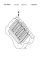
- FIG. 9 is a pictorial representation of a layer of deposited metal used to interconnect various circuit elements in FIGS. 8A and 8B, and depicts a remaining portion of the library cell of FIGS. 8A and 8B;
- FIG. 10 is a schematic segment of a protection cell generally similar to those of the preceding figures, but adapted for use with PMOS FET's fabricated upon n-type substrates;
- FIG. 11 is a simplified and stylized cut-away side view of the SCR portion of the protection circuit in FIG. 10 for PMOS transistors fabricated upon an n-type substrate;
- FIGS. 12A-C are schematic illustrations of alternate trigger circuits that could be used in connection with the SCR's in the protection cells of FIGS. 6, 7 and 10.
- FIG. 4 wherein is shown a simplified partial schematic of an IC having improved ESD protection for output drivers operating with a dirty ground.
- the bulk material of the substrate is p material, so the figure is similar to FIG. 2, and corresponding elements have the same reference characters.
- FIG. 4 contains additional elements, however, which provide the aforementioned improvement in ESD protection.
- driver transistor 17 for pad 24, served by DGND 16 is shunted by protective device 31.
- driver transistor 20 for pad 25, also served by DGND 16 is shunted by protective device 32.
- Protective devices 31 and 32 are depicted as SCR's, but it will be understood that other types of protective devices may be used, including but not limited to, field oxide punch through devices, field emission devices, spark gaps, switched transistors and zener diodes.
- SCR's 31 and 32 are normally off. They are triggered on whenever the voltage across their respective output driver transistors (17 and 20, respectively) rises above a preset level.
- the trigger circuitry is not depicted in the figure, and is the subject matter a later figure as well as of the incorporated Application of Metz, Motley and Rieck.
- a source of positive charge zaps a pin bonded to a pad driven by a driver transistor served by DGND.
- the particular example depicted in the figure has a source of positive charge 29 zapping pad 24, and presumes that the location of charge dissipation is DGND, as indicated by the ground symbol 28.
- I ZAP This results in a (hole flow) current I ZAP that travels from pad 24 toward pad 16.
- I ZAP It is very undesirable for I ZAP to pass through the associated driver transistor 17, or for transistor 17 to experience elevated voltages relative to surrounding circuit elements. Both of these situations are prevented by triggering protective SCR 31, so that I ZAP flows through SCR 31 (and its all metal path to and from itself) rather than through anybody else.
- I ZAP does not flow through length of conductor 30 or diode 18, and especially not through resistance 19, while in addition the related problem of getting SCR 9 turned on is avoided.
- FIG. 4 depicts a case where the pad 24 for SIG 1 and the pad 25 for SIG 3 are each driven by transistors both served by the same dirty ground DGND 16.
- driver transistors 37 and 39 are each served by a different dirty ground: DGND 1 34 and DGND 2 35, respectively.
- DGND 1 34 and DGND 2 35 are connected by conductors 40 and 41, respectively, to SGND.
- protective SCR 36 is coupled between pads 24 and 34, while protective SCR 38 is coupled between pads 25 and 35. In this way protective SCR 36 shunts driver transistor 37 when needed, and protective SCR 38 shunts transistor 39.
- FIG. 6 wherein is shown a more detailed schematic arrangement of improved ESD protection for an IC.
- pad 24 for SIG 1 is pulled down to DGND by transistor 17 and up to DV DD by a transistor 52.
- DV DD Dirty V DD --a supply separate from and presumably not as clean and quiet as regular V DD .
- pad 25 for SIG 3 is pulled to DGND and DV DD by transistors 20 and 53, respectively.
- Diode 54 represents the parasitic diode at the drain of transistor 17, as well as the one at the source of transistor 52.
- Diode 55 represents similar parasitic diodes for transistors 20 and 53.
- Diodes 10, 51 and 56 each represent various instances of other classes of parasitic diodes formed by the fabrication of the transistors of the IC.
- Pad 24 is protected from positive ESD zaps by the SCR's and associated trigger circuitry belonging to a protection cell 43, whose extent is indicated by the dotted line.
- Pad 25 is likewise protected by protection cell 44, which is identical in nature to cell 43.
- Each protection cell (43, 44) includes two SCR's: one from the pad to each of GND and DGND.
- Each SCR (31, 9 & 32, 14) has an associated gate driver transistor (63, 61 & 64, 62, respectively) and an associated trigger circuit (45, 46 & 47, 48, respectively), all referenced to either GND or DGND, so as to be the same as the SCR.
- Each trigger circuit has four nodes. These are: Signal “S”, which is connected to the pad to be protected; Plus Power “+”, which is connected to V DD or DV DD , as appropriate; Minus Power "-”, which is connected to GND or DGND, as appropriate for the SCR to be triggered; and, Trigger "T”, which is connected to the gate driver transistor of the SCR to be triggered.
- a protection cell contains a pair of trigger circuits and a pair of SCR's (along with their respective gate driver transistors), with one member of each pair being coupled or referenced to GND and the members of the other pair being referenced to a dirty ground.
- V DD is the signal being protected as well as being the source of power, so nodes “S" and “+” are both connected to V DD .
- V DD could be protected to both GND and DGND at the same time by the use of a protection cell, such as 43 or 44. In such a case the "S" and "+" nodes of each of the two trigger circuits would be connected to V DD .
- DGND can be protected with respect to GND through the use of a protection cell such as 43 or 44.
- the instances (45-49) of the preferred trigger circuit shown in FIG. 6, and explained below, are merely exemplary. It will be understood that other trigger circuits might be suitable.
- the particular trigger circuit shown is one of several suitable circuits disclosed in the incorporated application of Metz, Motley and Rieck, and is intended to trigger an SCR (by turning on its associated gate driver transistor) whenever there is (with respect to the "-" node) a large positive voltage on the "S" node.
- This trigger circuit is ESD-powered, in that the energy of the ESD event itself supplies the power necessary to trigger the SCR, even when the IC is un-installed and there is no V DD .
- This trigger circuit is also one whose threshold is a function of V DD : low when it is absent and high when it is present.
- the low threshold is in the range of one to two volts, while the high threshold is in the range of eight to nine volts.
- the schematic of the preferred trigger circuit 45-49 is shown in FIG. 7, and is accompanied therein by a schematic representation of an SCR 65 (any of 9, 14, 31 or 32) and of an (output) driver (52, 53) for a pad (24, 25).
- SCR 65 any of 9, 14, 31 or 32
- SCR 65 any of 9, 14, 31 or 32
- pad driver 52, 53
- Metz, Motley and Rieck A more extensive explanation may be found in the incorporated patent application of Metz, Motley and Rieck.
- transistor 58 is off and transistor 59 is on, resulting in transistor 57 being off.
- the developing overvoltage from the zap to the pad (24, 25) is communicated to transistor 57 via well resistance R w+ and the PN junction 60 within the SCR itself.
- the overvoltage at the pad also causes transistor 58 to turn on (its gate stays at V DD for the conditions assumed here), which in turn turns on transistor 57.
- Both transistors 58 and 59 are now on, forming a voltage divider that raises the gate voltage to transistor 57.
- Transistor 57 then carries current (through well resistance R w+ and the PN junction 60), which in turn triggers the SCR 65.
- R w+ well resistance
- R w+ well resistance
- the fractions next to the FET's in the trigger circuit 45-49 indicate a useful range of device sizes.
- the SCR is, of course, huge in comparison to the FET's, since it is necessary for it to carry a relatively large current, say on the order of one to one and a half amperes.
- FIGS. 8A and 8B wherein are depicted fanciful sectional views of a trigger/SCR portion of an integrated circuit; the portion shown may be a library cell used a plurality of times in an integrated circuit.
- FIG. 8A depicts the trigger portion corresponding to trigger circuits 45 and 46 (or 47 & 48) of FIG. 6, while FIG. 8B depicts SCR's and gate driver transistors corresponding to SCR's 31 and 9 and associated gate driver transistors 63 and 61 (or 32, 14 & 64, 62).
- any adjacent circuitry has been suppressed, and the substrate 66 shown as if sawn along lines 69 and 70 with the resulting two pieces opened away from each other as though edge 67 were a hinge.
- FIGS. 8A and 8B are the various dopants and structural elements resulting from the fabrication of MOS transistors and SCR's. The depictions are not complete as to all layers of material deposited onto the substrate; FIG. 9 depicts an interconnecting layer of metalization deposited upon an intervening layer of glass. Finally, these figures are not to scale, particularly with regard to the depth of the substrate 66, which is of silicon doped to be p-. In other respects, however, they are descriptive in a way that is quite useful.
- shaded region 71 is an n-well that is common to both FIGS. 8A and 8B.
- Shaded regions 72-75 are doped to be n+, while shaded regions 76-79 are doped to be p+.
- the heavy dark line 80 represents a layer of gate oxide about three hundred angstroms thick.
- the dotted region 81 above the layer of gate oxide 80 is polysilicon; it is a medium resistance material used to form conductive gate surfaces for MOS transistors.
- FIG. 8A depicts four MOS transistors whose gates are formed by regions of polysilicon 82, 83, 84 and 85.
- regions 72, 82 and 73 form MOS transistor 59 (see FIG. 7) of trigger circuit 45 (in FIG. 6).
- regions 76, 83 and 77 form MOS transistor 58 (referencing the same figures).
- regions 75, 85 and 74 form MOS transistor 59 (a different instance!) of trigger circuit 46, while regions 79, 84 and 78 form the associated MOS transistor 58, also of trigger circuit 46.
- FIG. 8B depicts the associated SCR's and their gate driver transistors.
- like styles of shading denote the same dopant or other deposited material.
- shaded region 71 is the common n-well (i.e., it is common to both figures).
- Regions 86 and 87 are doped to be n+, while line 92 denotes a layer of gate oxide and the dotted region 91 thereabove represents a deposited layer of polysilicon.
- elements 86, 87, 91 and 92 form the instance (in FIG. 7) of FET 57 that is connected to DGND.
- elements 89, 90, 93 and 94 form the instance of FET 57 that is connected to GND.
- transistor 57 its source is connected to the collector of a bi-polar transistor that is interior to the associated SCR 65. That is, regions 87 and 89 are each the source of a FET and the collector of a bi-polar npn structure within the SCR.
- the instance of SCR 65 that connects the pad (24, 25) to DGND is made up of regions 95, 71,66 and 86.
- the instance of SCR 65 that connects that same pad to GND is made up of regions 96, 71, 66 and 90. Note that these instances of SCR's 65 are really a great deal longer in the direction of the arrow 95 than is depicted in FIG. 8B. That is, if the width of gates 82-85 in FIG. 8A were ten microns, then the width of the SCR's in FIG. 8B would be on the order of two to four hundred microns.
- FIG. 9 depicts a pattern of metalization and its interconnection with the integrated circuit elements shown in FIGS. 8A and 8B.
- FIG. 9 it should be understood that it is a top view of the pattern of metalization, and that as a top view it applies to FIGS. 8A and 8B as though their contents were not sawn apart, but were instead joined along lines 67-70.
- integrated circuit structure depicted in FIGS. 8A and 8B are coated with a layer of "glass” (e.g., silicon dioxide), into which holes are etched to allow the metal to make electrical contact with elements of the integrated circuit below the glass.
- glass e.g., silicon dioxide
- FIG. 9 no attempt has been made to illustrate the layer of glass, since it is everywhere, except where there are holes therein. What is shown is the pattern of the metalization; it is depicted by the heavy lines, such as 96, 99 and 102. The locations of holes in the glass where the metalization contacts the integrated circuit elements below are indicated by the rectangular regions filled with cross hatching. Finally, the light lines denote the broad outlines of the integrated circuit structure shown in FIGS. 8A and 8B. These light lines are included for reference (even when they ought to be obscured by the overlying metal), so that the registration of the metalization to those integrated circuit elements below may be appreciated.
- FIG. 9 shows a metal trace 96 that is GND and that makes contact with elements of FIGS. 8A and 8B at locations 97 and 98, as indicated by the cross-hatching.
- Metal trace 96 serves as the "-" node for the trigger circuit (46, 48) referenced to GND.
- a metal trace 99 that is DGND makes contact at locations 100 and 101, and serves as the "-" node for the trigger circuit (45, 47) referenced to DGND.
- V DD is supplied by a metal trace 102 that make contact at region 103; it serves as the "+" node for the different trigger circuits (45 & 46 or 47 & 48).
- Metal trace 104 connects via region 105 to the pad (24, 25) and via regions 106-109 to the two trigger circuits (45 & 46 or 47 & 48) and the two SCR's (31 & 9 or 32 & 14, respectively).
- Metal trace 104 serves as the "S" node for both trigger circuits (45 & 46 or 47 & 48).
- trace 110 which makes contact at regions 111-113. This trace serves as the "T" node for the ESD protection trigger circuit (46, 48) referenced to GND and that is coupled to the SCR (9,14) connected between the pad and GND.
- trace 114 makes contact at regions 115-117 and serves as the "T" node for the ESD protection trigger circuit (45, 47) referenced to DGND and that is coupled to the SCR (31, 32) connected between the pad and DGND.
- the location of the protection cells (43, 44) within the integrated circuit is of some interest.
- the interior region of the integrated circuit contains all the particular circuitry that meets the motive for having the integrated circuit in the first place.
- the various bonding pads that receive bonding wires connecting to the pins that traverse the outer packaging.
- Around the very outside of the die runs a perimeter ring.
- the preferred location for the ESD protection cells (43, 44) disclosed herein is just inside the perimeter ring, between it and the bonding pads.
- the protection cells can incorporate SCR's, and the trigger circuit therefor can be either of an active or of a passive variety.
- V DD is always positive with respect to GND.
- ESD event of particular interest is when the pad is zapped negative with respect to V DD (or to DV DD ).
- FIG. 10 wherein is shown a schematic segment of such a protection cell 127. It includes two SCR's 119 and 120, respectively connected between the bonding pad 118 and V DD or DV DD .
- SCR 119 is triggered by turning on FET 125;
- SCR 120 is likewise triggered by turning on FET 126.
- Each of these FET's is controlled by the "T" node of a respective trigger circuit 123 and 124.
- Each of the trigger circuits is connected to an associated power supply (V DD or DV DD ), as well as to the pad 118 and (probably) to GND (or perhaps DGND).
- trigger circuits 123 and 124 What each of trigger circuits 123 and 124 must do is turn on their associated trigger FET (125 and 126, respectively) when there is an ESD event, but avoid false triggers such as during the legitimate onset of the power supplies.
- the particular trigger circuits 45-49 disclosed for use with p-type substrates are directly usable as trigger circuits 123 and 124, provided that they are connected as shown in FIG. 10.
- the "S” node is connected to the power supply: i.e., V DD 121 or DV DD 122.
- the "+" nodes are connected to a common point "X" 138 with the integrated circuit. All other "+” nodes from other trigger circuits would also be common to "X” also, unless subject to the circumstance described in a subsequent paragraph below.
- the common point "X" 128 is connected to a bonding pad 129.
- a bonding wire 130 connects pad 129 to a pin 131 on the IC's package.
- Pin 131 mates with contact 132 that is part of a socket on, or is a mounting hole in, a printed circuit board (PCB) or other environment external to the integrated circuit.
- Contact 132 is electrically coupled to the instance of V DD 133 that is distributed to the various IC's carried by the PCB or that are otherwise in the external environment.
- the V DD thus brought onto the IC to point "X" via pin 131 should not be confused with the regular "on chip” V DD 121 that is otherwise brought onto the IC, anyway.
- common point “X” is to provide a signal source on the IC that is just like V DD whenever the IC is installed in an external environment, but that has no internal connection to the regular "on chip” V DD when the IC exists in isolation; e.g., is not installed in an external environment, such as a PCB.
- V DD 121 The reason that the "+" node cannot be connected to the "on chip” V DD 121 is as follows: Suppose that there were, for an uninstalled IC, and ESD event between the pad and V DD (or DV DD ), and that the pad was at the positive end or side of that event. If the "+" node were connected to V DD 121, it would turn the off the PFET 58 in the trigger circuit 45-49 (refer to FIG. 7). That would drastically reduce the effectiveness of the trigger circuit, since it is intended that PFET 58 turn on during such an ESD event.
- the threshold voltage for case #1 events is "high”; i.e., the voltage at the midpoint of the divider plus the turn-on voltage for transistor 57.
- transistors 58 and 59 are normally both off, and the ESD event turns transistor 58 on and supplies the energy to fire the SCR.
- the threshold voltage for case #2 events is "low”; i.e., the sum of the turn-on voltages for transistors 58 and 57.
- V DD is not an appropriate auxiliary mode control signal for the trigger circuit, as it can be when the path to be protected is pad to GND or pad to DGND (i.e., V DD is not part of the path).
- Protection circuit #2 operates with V DD #2 connected to its node “S” and isolated V DD #1 On its node “+”. Now suppose that, for whatever reason (failure of an element in some system, oversight in assembling a system, etc.), V DD #2 is present without isolated V DD #1. This could easily look like a case #2 ESD event, turning on transistor 58 in protection circuit #2. That would trigger its associated SCR, which is bad news for the IC and for the V DD #2 power supply. For example, suppose V DD #2 were a long term battery supply, while V DD #1 were a line operated supply susceptible to being turned off. The solution is to supply protection circuit #2 with isolated V DD #2 instead of with isolated V DD #1. Isolated V DD #2 would be derived ("by jumper", as it were) in the same way that V DD #1 is produced.
- a pad-positive ESD event occurs while the IC is in operation and while pull-up transistor 52 or 53 is on. Now the ESD event is communicated to the gates of transistors 58 and 59, with the possibility of that turning transistor 58 off and transistor 59 on--exactly the opposite of what is desired. In such a case momentary breakdown of transistor 57 is what saves the day.
- FIG. 11 wherein is shown a simplified cross sectional view of the SCR portion of a protection cell to be used in n-type substrates.
- FIG. 11 is to be understood as a counterpart to FIG. 8B and the SCR-part of FIG. 9, although for the sake of simplicity it is presented in a slightly different format. It will of course be appreciated that FIG. 11 does not "go with” FIG. 8A "as is", since, if for no other reason, they have different substrate dopings. We omit the n-type substrate counterpart to FIG. 8A, since it is readily understood that it could have essentially the same structure as FIG.
- FIG. 11 the diagonal shading used to denote p-type doping, and the horizontal shading used to denote n-type doping, are local to FIG. 11.
- the heavy lines denoting oxide, the dotted shading for polysilicon, and the cross-hatching for metal are, however, the same as used in FIGS. 8A-B and in FIG. 9.
- the n-type substrate 138 includes p-wells 139, 140 and 141.
- P-wells 139 and 140 have respective metal traces 142 and 143 deposited thereon; these are connected to V DD and DV DD , respectively.
- that layer of glass has been omitted, and the only metalization shown is that which would be in a hole in the omitted layer of glass.
- P-well 141 contains within it interior n-wells 150 and 151, each of which are connected by metalization 153 to the pad 154 to be protected.
- the pnpn structure forming the SCR that protects the pad 154 relative to V DD is made up of regions 139, 138, 141 and 150, respectively.
- the pnpn structure forming the SCR that protects the pad 154 relative to DV DD is made up of regions 140, 138,141 and 151, respectively.
- Each SCR has a trigger FET. These are formed by the layers of oxide 144 and 145, polysilicon 146 and 147, and metal contacts 148 and 149 that serve as interconnections to the respective trigger circuits.
- FIGS. 12A-C show other possible (fixed threshold) trigger circuits 153, 154 and 155 that might be used in place of trigger circuits 45-49 and 123 and 124.
- the simplest of these is shown in FIG. 12A.
- trigger circuit 153 consists simply of a conductor between nodes "T" and "-”. In this case transistor 57 is simply relied upon to momentarily break down and thus trigger the associated SCR.
- FIG. 12B a resistor 157 is connected between nodes "T" and "-" for trigger circuit 154. Operation of trigger circuit 154 is similar to trigger circuit 153 of FIG. 12A.
- FIG. 12C shows a trigger circuit 155 comprising a FET 159 whose drain is the "T” node and whose source is the "-" node.
- the gate of the FET 159 is the "S” node for n-type substrates and the "+” node for p-type substrates.
- This trigger circuit (155) allows the gate of transistor 57 to float during case #2 ESD events. This permits some coupling of the ESD voltage to the gate through the FET 57 itself, and allows FET 57 to break down at a somewhat lower voltage than required when the gate is grounded as in FIG. 12A.
Abstract
Description
TABLE 1 ______________________________________ "+" = V.sub.DD "S" = V.sub.DD & "X" = ISO V.sub.DD ______________________________________ IN BOARD IN BOARD V.sub.DD on:Case # 1 V.sub.DD on:Case # 1 V.sub.DD off: Case #2 (effectively) V.sub.DD off:Case # 3 OUT OF BOARD OUT OF BOARD V.sub.DD on: Absurd V.sub.DD on: Absurd V.sub.DD off:Case # 2 V.sub.DD off:Case # 2 ______________________________________
Claims (12)
Priority Applications (4)
| Application Number | Priority Date | Filing Date | Title |
|---|---|---|---|
| US08/190,756 US5561577A (en) | 1994-02-02 | 1994-02-02 | ESD protection for IC's |
| GB9804387A GB2319893B (en) | 1994-02-02 | 1995-01-20 | ESD Protection circuit |
| GB9501161A GB2286287B (en) | 1994-02-02 | 1995-01-20 | Improved ESD protection for IC's |
| JP7014473A JPH07263566A (en) | 1994-02-02 | 1995-01-31 | Integrated circuit to which esd protection is applied |
Applications Claiming Priority (1)
| Application Number | Priority Date | Filing Date | Title |
|---|---|---|---|
| US08/190,756 US5561577A (en) | 1994-02-02 | 1994-02-02 | ESD protection for IC's |
Publications (1)
| Publication Number | Publication Date |
|---|---|
| US5561577A true US5561577A (en) | 1996-10-01 |
Family
ID=22702632
Family Applications (1)
| Application Number | Title | Priority Date | Filing Date |
|---|---|---|---|
| US08/190,756 Expired - Fee Related US5561577A (en) | 1994-02-02 | 1994-02-02 | ESD protection for IC's |
Country Status (3)
| Country | Link |
|---|---|
| US (1) | US5561577A (en) |
| JP (1) | JPH07263566A (en) |
| GB (1) | GB2286287B (en) |
Cited By (29)
| Publication number | Priority date | Publication date | Assignee | Title |
|---|---|---|---|---|
| US5751051A (en) * | 1995-07-18 | 1998-05-12 | Nec Corporation | Semiconductor device equipped with electrostatic breakdown protection circuit |
| US5886862A (en) * | 1997-11-26 | 1999-03-23 | Digital Equipment Corporation | Cross-referenced electrostatic discharge protection systems and methods for power supplies |
| US6144542A (en) * | 1998-12-15 | 2000-11-07 | Taiwan Semiconductor Manufacturing Co., Ltd. | ESD bus lines in CMOS IC's for whole-chip ESD protection |
| WO2001011685A1 (en) * | 1999-08-06 | 2001-02-15 | Sarnoff Corporation | Double triggering mechanism for achieving faster turn-on |
| US6258634B1 (en) | 1998-06-19 | 2001-07-10 | National Semiconductor Corporation | Method for manufacturing a dual-direction over-voltage and over-current IC protection device and its cell structure |
| US6515839B1 (en) * | 1993-09-29 | 2003-02-04 | Hoang P. Nguyen | Electronic discharge protection system for mixed voltage application specific circuit design |
| US6529359B1 (en) * | 1999-08-06 | 2003-03-04 | Sarnoff Corporation | Circuits for dynamic turn off of NMOS output drivers during EOS/ESD stress |
| US6537890B2 (en) * | 2000-09-15 | 2003-03-25 | Seung Ki Joo | Poly-silicon thin film transistor having back bias effects and fabrication method thereof |
| US20030076636A1 (en) * | 2001-10-23 | 2003-04-24 | Ming-Dou Ker | On-chip ESD protection circuit with a substrate-triggered SCR device |
| US6639771B2 (en) | 2001-03-12 | 2003-10-28 | Pericom Semiconductor Corp. | Internet ESD-shunt diode protected by delayed external MOSFET switch |
| US20030214773A1 (en) * | 2002-04-19 | 2003-11-20 | Nobutaka Kitagawa | Protection circuit section for semiconductor circuit system |
| US6661863B1 (en) | 1999-04-16 | 2003-12-09 | Infineon Technologies North America Corp. | Phase mixer |
| EP1368874A1 (en) * | 2001-03-16 | 2003-12-10 | Sarnoff Corporation | Electrostatic discharge protection structures for high speed technologies with mixed and ultra-low voltage supplies |
| US20050036862A1 (en) * | 2003-06-23 | 2005-02-17 | Koji Fujii | Wafer transfer equipment and semiconductor device manufacturing apparatus using wafer transfer equipment |
| US20050057866A1 (en) * | 2001-03-16 | 2005-03-17 | Mergens Markus Paul Josef | Electrostatic discharge protection structures for high speed technologies with mixed and ultra-low voltage supplies |
| US20060170054A1 (en) * | 2004-12-15 | 2006-08-03 | Mergens Markus P J | Device having a low-voltage trigger element |
| US20070069310A1 (en) * | 2005-09-26 | 2007-03-29 | Samsung Electronics Co., Ltd. | Semiconductor controlled rectifiers for electrostatic discharge protection |
| US20070097570A1 (en) * | 2004-10-01 | 2007-05-03 | International Business Machines Corporation | High voltage esd power clamp |
| US7327541B1 (en) | 1998-06-19 | 2008-02-05 | National Semiconductor Corporation | Operation of dual-directional electrostatic discharge protection device |
| KR100801863B1 (en) | 2000-04-10 | 2008-02-12 | 프리스케일 세미컨덕터, 인크. | Electrostatic dischargeESD protection circuit |
| US20090045436A1 (en) * | 2007-08-16 | 2009-02-19 | Stefaan Verleye | Localized trigger esd protection device |
| US20090052102A1 (en) * | 2007-08-20 | 2009-02-26 | Kabushiki Kaisha Toshiba | Semiconductor device |
| US20100020455A1 (en) * | 2008-07-24 | 2010-01-28 | Robert Bosch Gmbh | Passive network for electrostatic protection of integrated circuits |
| US20100118457A1 (en) * | 2008-11-10 | 2010-05-13 | Kook-Whee Kwak | Electrostatic discharge protection circuit |
| US20100219792A1 (en) * | 2009-02-13 | 2010-09-02 | Kazuhiro Tsumura | Battery protection circuit device |
| US20120275075A1 (en) * | 2011-04-27 | 2012-11-01 | Stmicroelectronics Sa | Electrostatic Discharge Protection Device |
| US8467162B2 (en) | 2010-12-30 | 2013-06-18 | United Microelectronics Corp. | ESD protection circuit and ESD protection device thereof |
| US10193338B2 (en) * | 2017-05-05 | 2019-01-29 | Synaptics Incorporated | Voltage triggered edge insensitive protection circuit |
| US10361187B1 (en) * | 2018-02-13 | 2019-07-23 | Powerchip Semiconductor Manufacturing Corporation | Electrostatic discharge protection device |
Families Citing this family (9)
| Publication number | Priority date | Publication date | Assignee | Title |
|---|---|---|---|---|
| DE19507313C2 (en) * | 1995-03-02 | 1996-12-19 | Siemens Ag | Semiconductor component with protective structure for protection against electrostatic discharge |
| US5671111A (en) * | 1995-10-30 | 1997-09-23 | Motorola, Inc. | Apparatus for electro-static discharge protection in a semiconductor device |
| KR0166509B1 (en) * | 1995-12-29 | 1999-01-15 | 김주용 | Electrostatic protection circuit |
| US6724603B2 (en) | 2002-08-09 | 2004-04-20 | Motorola, Inc. | Electrostatic discharge protection circuitry and method of operation |
| US7446990B2 (en) | 2005-02-11 | 2008-11-04 | Freescale Semiconductor, Inc. | I/O cell ESD system |
| US7808117B2 (en) | 2006-05-16 | 2010-10-05 | Freescale Semiconductor, Inc. | Integrated circuit having pads and input/output (I/O) cells |
| US7777998B2 (en) | 2007-09-10 | 2010-08-17 | Freescale Semiconductor, Inc. | Electrostatic discharge circuit and method therefor |
| JP5232444B2 (en) * | 2007-11-12 | 2013-07-10 | ルネサスエレクトロニクス株式会社 | Semiconductor integrated circuit |
| JP5548284B2 (en) * | 2013-02-11 | 2014-07-16 | ルネサスエレクトロニクス株式会社 | Semiconductor integrated circuit |
Citations (3)
| Publication number | Priority date | Publication date | Assignee | Title |
|---|---|---|---|---|
| US5140401A (en) * | 1991-03-25 | 1992-08-18 | United Microelectronics Corporation | CMOS ESD protection circuit with parasitic SCR structures |
| US5239440A (en) * | 1989-12-19 | 1993-08-24 | National Semiconductor Corporation | Electrostatic discharge protection for integrated circuits |
| US5289334A (en) * | 1992-04-02 | 1994-02-22 | United Microelectronics Corporation | CMOS on-chip ESD protection circuit and semiconductor structure |
Family Cites Families (1)
| Publication number | Priority date | Publication date | Assignee | Title |
|---|---|---|---|---|
| JPH061802B2 (en) * | 1989-03-14 | 1994-01-05 | 株式会社東芝 | Semiconductor device |
-
1994
- 1994-02-02 US US08/190,756 patent/US5561577A/en not_active Expired - Fee Related
-
1995
- 1995-01-20 GB GB9501161A patent/GB2286287B/en not_active Expired - Fee Related
- 1995-01-31 JP JP7014473A patent/JPH07263566A/en active Pending
Patent Citations (3)
| Publication number | Priority date | Publication date | Assignee | Title |
|---|---|---|---|---|
| US5239440A (en) * | 1989-12-19 | 1993-08-24 | National Semiconductor Corporation | Electrostatic discharge protection for integrated circuits |
| US5140401A (en) * | 1991-03-25 | 1992-08-18 | United Microelectronics Corporation | CMOS ESD protection circuit with parasitic SCR structures |
| US5289334A (en) * | 1992-04-02 | 1994-02-22 | United Microelectronics Corporation | CMOS on-chip ESD protection circuit and semiconductor structure |
Cited By (46)
| Publication number | Priority date | Publication date | Assignee | Title |
|---|---|---|---|---|
| US6515839B1 (en) * | 1993-09-29 | 2003-02-04 | Hoang P. Nguyen | Electronic discharge protection system for mixed voltage application specific circuit design |
| US5751051A (en) * | 1995-07-18 | 1998-05-12 | Nec Corporation | Semiconductor device equipped with electrostatic breakdown protection circuit |
| US5886862A (en) * | 1997-11-26 | 1999-03-23 | Digital Equipment Corporation | Cross-referenced electrostatic discharge protection systems and methods for power supplies |
| US5999386A (en) * | 1997-11-26 | 1999-12-07 | Compaq Computer Corporation | Cross-referenced electrostatic discharge protection systems and methods for power supplies |
| US7936020B1 (en) | 1998-06-19 | 2011-05-03 | National Semiconductor Corporation | Dual-directional electrostatic discharge protection device |
| US6258634B1 (en) | 1998-06-19 | 2001-07-10 | National Semiconductor Corporation | Method for manufacturing a dual-direction over-voltage and over-current IC protection device and its cell structure |
| US6365924B1 (en) | 1998-06-19 | 2002-04-02 | National Semiconductor Corporation | Dual direction over-voltage and over-current IC protection device and its cell structure |
| US20020074604A1 (en) * | 1998-06-19 | 2002-06-20 | Wang Albert Z. H. | Dual direction over-voltage and over-current IC protection device and its cell structure |
| US7327541B1 (en) | 1998-06-19 | 2008-02-05 | National Semiconductor Corporation | Operation of dual-directional electrostatic discharge protection device |
| US8305722B2 (en) | 1998-06-19 | 2012-11-06 | National Semiconductor Corporation | Dual-directional electrostatic discharge protection method |
| US6144542A (en) * | 1998-12-15 | 2000-11-07 | Taiwan Semiconductor Manufacturing Co., Ltd. | ESD bus lines in CMOS IC's for whole-chip ESD protection |
| US6661863B1 (en) | 1999-04-16 | 2003-12-09 | Infineon Technologies North America Corp. | Phase mixer |
| US6618233B1 (en) | 1999-08-06 | 2003-09-09 | Sarnoff Corporation | Double triggering mechanism for achieving faster turn-on |
| US6529359B1 (en) * | 1999-08-06 | 2003-03-04 | Sarnoff Corporation | Circuits for dynamic turn off of NMOS output drivers during EOS/ESD stress |
| WO2001011685A1 (en) * | 1999-08-06 | 2001-02-15 | Sarnoff Corporation | Double triggering mechanism for achieving faster turn-on |
| KR100801863B1 (en) | 2000-04-10 | 2008-02-12 | 프리스케일 세미컨덕터, 인크. | Electrostatic dischargeESD protection circuit |
| US6537890B2 (en) * | 2000-09-15 | 2003-03-25 | Seung Ki Joo | Poly-silicon thin film transistor having back bias effects and fabrication method thereof |
| US6639771B2 (en) | 2001-03-12 | 2003-10-28 | Pericom Semiconductor Corp. | Internet ESD-shunt diode protected by delayed external MOSFET switch |
| EP1368874A1 (en) * | 2001-03-16 | 2003-12-10 | Sarnoff Corporation | Electrostatic discharge protection structures for high speed technologies with mixed and ultra-low voltage supplies |
| US6768616B2 (en) | 2001-03-16 | 2004-07-27 | Sarnoff Corporation | Electrostatic discharge protection structures for high speed technologies with mixed and ultra-low voltage supplies |
| US20050057866A1 (en) * | 2001-03-16 | 2005-03-17 | Mergens Markus Paul Josef | Electrostatic discharge protection structures for high speed technologies with mixed and ultra-low voltage supplies |
| US7589944B2 (en) | 2001-03-16 | 2009-09-15 | Sofics Bvba | Electrostatic discharge protection structures for high speed technologies with mixed and ultra-low voltage supplies |
| EP1368874A4 (en) * | 2001-03-16 | 2007-02-28 | Sarnoff Corp | Electrostatic discharge protection structures for high speed technologies with mixed and ultra-low voltage supplies |
| US20030076636A1 (en) * | 2001-10-23 | 2003-04-24 | Ming-Dou Ker | On-chip ESD protection circuit with a substrate-triggered SCR device |
| US7106562B2 (en) * | 2002-04-19 | 2006-09-12 | Kabushiki Kaisha Toshiba | Protection circuit section for semiconductor circuit system |
| US20030214773A1 (en) * | 2002-04-19 | 2003-11-20 | Nobutaka Kitagawa | Protection circuit section for semiconductor circuit system |
| US20050036862A1 (en) * | 2003-06-23 | 2005-02-17 | Koji Fujii | Wafer transfer equipment and semiconductor device manufacturing apparatus using wafer transfer equipment |
| US7457086B2 (en) * | 2004-10-01 | 2008-11-25 | International Business Machines Corporation | High voltage ESD power clamp |
| US20070097570A1 (en) * | 2004-10-01 | 2007-05-03 | International Business Machines Corporation | High voltage esd power clamp |
| US20060170054A1 (en) * | 2004-12-15 | 2006-08-03 | Mergens Markus P J | Device having a low-voltage trigger element |
| US7763940B2 (en) * | 2004-12-15 | 2010-07-27 | Sofics Bvba | Device having a low-voltage trigger element |
| US20070069310A1 (en) * | 2005-09-26 | 2007-03-29 | Samsung Electronics Co., Ltd. | Semiconductor controlled rectifiers for electrostatic discharge protection |
| US20090045436A1 (en) * | 2007-08-16 | 2009-02-19 | Stefaan Verleye | Localized trigger esd protection device |
| US7973334B2 (en) * | 2007-08-16 | 2011-07-05 | Sofics Bvba | Localized trigger ESD protection device |
| US20090052102A1 (en) * | 2007-08-20 | 2009-02-26 | Kabushiki Kaisha Toshiba | Semiconductor device |
| US20100020455A1 (en) * | 2008-07-24 | 2010-01-28 | Robert Bosch Gmbh | Passive network for electrostatic protection of integrated circuits |
| US9343900B2 (en) | 2008-07-24 | 2016-05-17 | Robert Bosch Gmbh | Passive network for electrostatic protection of integrated circuits |
| US20100118457A1 (en) * | 2008-11-10 | 2010-05-13 | Kook-Whee Kwak | Electrostatic discharge protection circuit |
| US20100219792A1 (en) * | 2009-02-13 | 2010-09-02 | Kazuhiro Tsumura | Battery protection circuit device |
| US8294422B2 (en) * | 2009-02-13 | 2012-10-23 | Seiko Instruments Inc. | Battery protection circuit device |
| TWI493820B (en) * | 2009-02-13 | 2015-07-21 | Seiko Instr Inc | Battery protection circuit device |
| US8467162B2 (en) | 2010-12-30 | 2013-06-18 | United Microelectronics Corp. | ESD protection circuit and ESD protection device thereof |
| US8711535B2 (en) | 2010-12-30 | 2014-04-29 | United Microelectronics Corp. | ESD protection circuit and ESD protection device thereof |
| US20120275075A1 (en) * | 2011-04-27 | 2012-11-01 | Stmicroelectronics Sa | Electrostatic Discharge Protection Device |
| US10193338B2 (en) * | 2017-05-05 | 2019-01-29 | Synaptics Incorporated | Voltage triggered edge insensitive protection circuit |
| US10361187B1 (en) * | 2018-02-13 | 2019-07-23 | Powerchip Semiconductor Manufacturing Corporation | Electrostatic discharge protection device |
Also Published As
| Publication number | Publication date |
|---|---|
| GB2286287B (en) | 1998-07-29 |
| JPH07263566A (en) | 1995-10-13 |
| GB2286287A (en) | 1995-08-09 |
| GB9501161D0 (en) | 1995-03-08 |
Similar Documents
| Publication | Publication Date | Title |
|---|---|---|
| US5561577A (en) | ESD protection for IC's | |
| US7782583B2 (en) | Electrostatic discharge protection device having low junction capacitance and operational voltage | |
| US5721656A (en) | Electrostatc discharge protection network | |
| US7242062B2 (en) | Semiconductor apparatus with improved ESD withstanding voltage | |
| JPH0758289A (en) | Semiconductor device | |
| US6239958B1 (en) | Electrostatic damage protection circuit and dynamic random access memory | |
| JPH0693497B2 (en) | Complementary MIS integrated circuit | |
| US5493133A (en) | PNP punchthrough-assisted protection device for special applications in CMOS technologies | |
| KR100399266B1 (en) | Semiconductor integrated circuit | |
| US5892262A (en) | Capacitor-triggered electrostatic discharge protection circuit | |
| US6456474B2 (en) | Semiconductor integrated circuit | |
| KR950010872B1 (en) | Semiconductor integrated circuit device | |
| US5365103A (en) | Punchthru ESD device along centerline of power pad | |
| JP3559075B2 (en) | Polarity reversal protection device for integrated electronic circuits in CMOS technology | |
| KR19980024056A (en) | Semiconductor integrated circuit device | |
| EP0292327A2 (en) | Electrostatic breakdown protection circuits | |
| GB2319893A (en) | ESD protection device with a trigger circuit | |
| US6680512B2 (en) | Semiconductor device having an integral protection circuit | |
| US6833590B2 (en) | Semiconductor device | |
| US20050127444A1 (en) | Semiconductor integrated circuit | |
| US6583475B2 (en) | Semiconductor device | |
| JP2940506B2 (en) | Semiconductor device | |
| US6459555B1 (en) | Integrated circuit comprising analog and digital sub-circuits with improved over-voltage protection and reduced substrate-noise coupling | |
| US6538291B1 (en) | Input protection circuit | |
| JPH10294383A (en) | Input protection diode |
Legal Events
| Date | Code | Title | Description |
|---|---|---|---|
| AS | Assignment |
Owner name: HEWLETT-PACKARD COMPANY, CALIFORNIA Free format text: ASSIGNMENT OF ASSIGNORS INTEREST;ASSIGNOR:MOTLEY, GORDON W.;REEL/FRAME:007112/0767 Effective date: 19940201 |
|
| FPAY | Fee payment |
Year of fee payment: 4 |
|
| AS | Assignment |
Owner name: HEWLETT-PACKARD COMPANY, A DELAWARE CORPORATION, C Free format text: MERGER;ASSIGNOR:HEWLETT-PACKARD COMPANY, A CALIFORNIA CORPORATION;REEL/FRAME:010841/0649 Effective date: 19980520 |
|
| AS | Assignment |
Owner name: AGILENT TECHNOLOGIES INC, CALIFORNIA Free format text: ASSIGNMENT OF ASSIGNORS INTEREST;ASSIGNOR:HEWLETT-PACKARD COMPANY;REEL/FRAME:010977/0540 Effective date: 19991101 |
|
| FEPP | Fee payment procedure |
Free format text: PAYOR NUMBER ASSIGNED (ORIGINAL EVENT CODE: ASPN); ENTITY STATUS OF PATENT OWNER: LARGE ENTITY |
|
| FPAY | Fee payment |
Year of fee payment: 8 |
|
| AS | Assignment |
Owner name: AVAGO TECHNOLOGIES GENERAL IP PTE. LTD., SINGAPORE Free format text: ASSIGNMENT OF ASSIGNORS INTEREST;ASSIGNOR:AGILENT TECHNOLOGIES, INC.;REEL/FRAME:017207/0020 Effective date: 20051201 |
|
| REMI | Maintenance fee reminder mailed | ||
| LAPS | Lapse for failure to pay maintenance fees | ||
| STCH | Information on status: patent discontinuation |
Free format text: PATENT EXPIRED DUE TO NONPAYMENT OF MAINTENANCE FEES UNDER 37 CFR 1.362 |
|
| FP | Lapsed due to failure to pay maintenance fee |
Effective date: 20081001 |
|
| AS | Assignment |
Owner name: AVAGO TECHNOLOGIES GENERAL IP (SINGAPORE) PTE. LTD Free format text: CORRECTIVE ASSIGNMENT TO CORRECT THE NAME OF THE ASSIGNEE PREVIOUSLY RECORDED ON REEL 017207 FRAME 0020. ASSIGNOR(S) HEREBY CONFIRMS THE ASSIGNMENT;ASSIGNOR:AGILENT TECHNOLOGIES, INC.;REEL/FRAME:038633/0001 Effective date: 20051201 |