US5556459A - Method for the reduction of SO2 emissions as generated by the fluid bed cement process - Google Patents
Method for the reduction of SO2 emissions as generated by the fluid bed cement process Download PDFInfo
- Publication number
- US5556459A US5556459A US08/482,927 US48292795A US5556459A US 5556459 A US5556459 A US 5556459A US 48292795 A US48292795 A US 48292795A US 5556459 A US5556459 A US 5556459A
- Authority
- US
- United States
- Prior art keywords
- potassium
- cement clinker
- source
- fluidized bed
- producing cement
- Prior art date
- Legal status (The legal status is an assumption and is not a legal conclusion. Google has not performed a legal analysis and makes no representation as to the accuracy of the status listed.)
- Expired - Lifetime
Links
- 239000004568 cement Substances 0.000 title claims abstract description 78
- 238000000034 method Methods 0.000 title claims abstract description 60
- 239000012530 fluid Substances 0.000 title abstract description 16
- ZLMJMSJWJFRBEC-UHFFFAOYSA-N Potassium Chemical compound [K] ZLMJMSJWJFRBEC-UHFFFAOYSA-N 0.000 claims abstract description 44
- 239000011591 potassium Substances 0.000 claims abstract description 44
- 229910052700 potassium Inorganic materials 0.000 claims abstract description 44
- 238000012545 processing Methods 0.000 claims abstract description 14
- 239000007787 solid Substances 0.000 claims abstract description 14
- 239000000203 mixture Substances 0.000 claims abstract description 12
- 239000002994 raw material Substances 0.000 claims abstract description 11
- OTYBMLCTZGSZBG-UHFFFAOYSA-L potassium sulfate Chemical compound [K+].[K+].[O-]S([O-])(=O)=O OTYBMLCTZGSZBG-UHFFFAOYSA-L 0.000 claims abstract description 10
- 229910052939 potassium sulfate Inorganic materials 0.000 claims abstract description 10
- 235000011151 potassium sulphates Nutrition 0.000 claims abstract description 10
- 235000012054 meals Nutrition 0.000 claims abstract description 7
- 239000000463 material Substances 0.000 claims description 52
- 239000000446 fuel Substances 0.000 claims description 10
- 239000002699 waste material Substances 0.000 claims description 8
- OKTJSMMVPCPJKN-UHFFFAOYSA-N Carbon Chemical group [C] OKTJSMMVPCPJKN-UHFFFAOYSA-N 0.000 claims description 7
- 229910052799 carbon Inorganic materials 0.000 claims description 7
- 239000000243 solution Substances 0.000 claims description 7
- 238000005453 pelletization Methods 0.000 claims description 5
- 238000002485 combustion reaction Methods 0.000 claims description 4
- 238000001125 extrusion Methods 0.000 claims description 4
- 238000001914 filtration Methods 0.000 claims description 4
- 239000011343 solid material Substances 0.000 claims description 4
- BVKZGUZCCUSVTD-UHFFFAOYSA-L Carbonate Chemical compound [O-]C([O-])=O BVKZGUZCCUSVTD-UHFFFAOYSA-L 0.000 claims description 3
- 239000012267 brine Substances 0.000 claims description 3
- XLYOFNOQVPJJNP-UHFFFAOYSA-M hydroxide Chemical compound [OH-] XLYOFNOQVPJJNP-UHFFFAOYSA-M 0.000 claims description 3
- HPALAKNZSZLMCH-UHFFFAOYSA-M sodium;chloride;hydrate Chemical compound O.[Na+].[Cl-] HPALAKNZSZLMCH-UHFFFAOYSA-M 0.000 claims description 3
- 238000007599 discharging Methods 0.000 claims 3
- NINIDFKCEFEMDL-UHFFFAOYSA-N Sulfur Chemical compound [S] NINIDFKCEFEMDL-UHFFFAOYSA-N 0.000 abstract description 13
- 238000002360 preparation method Methods 0.000 abstract description 13
- 239000011593 sulfur Substances 0.000 abstract description 13
- 229910052717 sulfur Inorganic materials 0.000 abstract description 13
- 238000002156 mixing Methods 0.000 abstract description 4
- 239000007858 starting material Substances 0.000 abstract description 2
- 239000000428 dust Substances 0.000 description 17
- KWYUFKZDYYNOTN-UHFFFAOYSA-M Potassium hydroxide Chemical compound [OH-].[K+] KWYUFKZDYYNOTN-UHFFFAOYSA-M 0.000 description 15
- 239000007789 gas Substances 0.000 description 14
- 239000008188 pellet Substances 0.000 description 14
- 239000003513 alkali Substances 0.000 description 12
- 239000000047 product Substances 0.000 description 9
- OSGAYBCDTDRGGQ-UHFFFAOYSA-L calcium sulfate Chemical compound [Ca+2].[O-]S([O-])(=O)=O OSGAYBCDTDRGGQ-UHFFFAOYSA-L 0.000 description 8
- BWHMMNNQKKPAPP-UHFFFAOYSA-L potassium carbonate Chemical compound [K+].[K+].[O-]C([O-])=O BWHMMNNQKKPAPP-UHFFFAOYSA-L 0.000 description 8
- 238000006243 chemical reaction Methods 0.000 description 6
- 229910052925 anhydrite Inorganic materials 0.000 description 5
- 239000000292 calcium oxide Substances 0.000 description 5
- ODINCKMPIJJUCX-UHFFFAOYSA-N calcium oxide Inorganic materials [Ca]=O ODINCKMPIJJUCX-UHFFFAOYSA-N 0.000 description 5
- 238000000354 decomposition reaction Methods 0.000 description 5
- 238000001035 drying Methods 0.000 description 5
- 238000004519 manufacturing process Methods 0.000 description 5
- 239000000654 additive Substances 0.000 description 4
- 239000003518 caustics Substances 0.000 description 4
- 239000003245 coal Substances 0.000 description 4
- 150000001875 compounds Chemical class 0.000 description 4
- 238000009826 distribution Methods 0.000 description 4
- 229910000027 potassium carbonate Inorganic materials 0.000 description 4
- 239000011734 sodium Substances 0.000 description 4
- 150000003467 sulfuric acid derivatives Chemical class 0.000 description 4
- XLYOFNOQVPJJNP-UHFFFAOYSA-N water Substances O XLYOFNOQVPJJNP-UHFFFAOYSA-N 0.000 description 4
- XEEYBQQBJWHFJM-UHFFFAOYSA-N Iron Chemical compound [Fe] XEEYBQQBJWHFJM-UHFFFAOYSA-N 0.000 description 3
- 239000011230 binding agent Substances 0.000 description 3
- 239000006227 byproduct Substances 0.000 description 3
- 238000001816 cooling Methods 0.000 description 3
- 238000006073 displacement reaction Methods 0.000 description 3
- 239000003517 fume Substances 0.000 description 3
- 239000002245 particle Substances 0.000 description 3
- 238000004513 sizing Methods 0.000 description 3
- 239000000126 substance Substances 0.000 description 3
- VEXZGXHMUGYJMC-UHFFFAOYSA-M Chloride anion Chemical compound [Cl-] VEXZGXHMUGYJMC-UHFFFAOYSA-M 0.000 description 2
- FAPWRFPIFSIZLT-UHFFFAOYSA-M Sodium chloride Chemical compound [Na+].[Cl-] FAPWRFPIFSIZLT-UHFFFAOYSA-M 0.000 description 2
- QAOWNCQODCNURD-UHFFFAOYSA-L Sulfate Chemical compound [O-]S([O-])(=O)=O QAOWNCQODCNURD-UHFFFAOYSA-L 0.000 description 2
- 238000004458 analytical method Methods 0.000 description 2
- 235000011132 calcium sulphate Nutrition 0.000 description 2
- 230000015556 catabolic process Effects 0.000 description 2
- 239000000571 coke Substances 0.000 description 2
- 238000005056 compaction Methods 0.000 description 2
- 238000006731 degradation reaction Methods 0.000 description 2
- 230000000694 effects Effects 0.000 description 2
- 239000003337 fertilizer Substances 0.000 description 2
- 229910052748 manganese Inorganic materials 0.000 description 2
- 239000011572 manganese Substances 0.000 description 2
- 150000003112 potassium compounds Chemical class 0.000 description 2
- 239000000843 powder Substances 0.000 description 2
- 239000000523 sample Substances 0.000 description 2
- 238000012216 screening Methods 0.000 description 2
- 238000003860 storage Methods 0.000 description 2
- VYZAMTAEIAYCRO-UHFFFAOYSA-N Chromium Chemical compound [Cr] VYZAMTAEIAYCRO-UHFFFAOYSA-N 0.000 description 1
- DGAQECJNVWCQMB-PUAWFVPOSA-M Ilexoside XXIX Chemical compound C[C@@H]1CC[C@@]2(CC[C@@]3(C(=CC[C@H]4[C@]3(CC[C@@H]5[C@@]4(CC[C@@H](C5(C)C)OS(=O)(=O)[O-])C)C)[C@@H]2[C@]1(C)O)C)C(=O)O[C@H]6[C@@H]([C@H]([C@@H]([C@H](O6)CO)O)O)O.[Na+] DGAQECJNVWCQMB-PUAWFVPOSA-M 0.000 description 1
- -1 KOH and K2 CO3 Chemical class 0.000 description 1
- PWHULOQIROXLJO-UHFFFAOYSA-N Manganese Chemical compound [Mn] PWHULOQIROXLJO-UHFFFAOYSA-N 0.000 description 1
- 229910004742 Na2 O Inorganic materials 0.000 description 1
- 239000011398 Portland cement Substances 0.000 description 1
- 238000010521 absorption reaction Methods 0.000 description 1
- 238000013459 approach Methods 0.000 description 1
- 230000015572 biosynthetic process Effects 0.000 description 1
- 238000001354 calcination Methods 0.000 description 1
- BRPQOXSCLDDYGP-UHFFFAOYSA-N calcium oxide Chemical compound [O-2].[Ca+2] BRPQOXSCLDDYGP-UHFFFAOYSA-N 0.000 description 1
- 229910052804 chromium Inorganic materials 0.000 description 1
- 239000011651 chromium Substances 0.000 description 1
- 238000004040 coloring Methods 0.000 description 1
- 230000003750 conditioning effect Effects 0.000 description 1
- 238000005243 fluidization Methods 0.000 description 1
- 230000002431 foraging effect Effects 0.000 description 1
- 238000002347 injection Methods 0.000 description 1
- 239000007924 injection Substances 0.000 description 1
- 239000002198 insoluble material Substances 0.000 description 1
- 239000013067 intermediate product Substances 0.000 description 1
- 229910052742 iron Inorganic materials 0.000 description 1
- 239000006193 liquid solution Substances 0.000 description 1
- 230000014759 maintenance of location Effects 0.000 description 1
- 238000012986 modification Methods 0.000 description 1
- 230000004048 modification Effects 0.000 description 1
- CHWRSCGUEQEHOH-UHFFFAOYSA-N potassium oxide Chemical compound [O-2].[K+].[K+] CHWRSCGUEQEHOH-UHFFFAOYSA-N 0.000 description 1
- 229910001950 potassium oxide Inorganic materials 0.000 description 1
- 239000002244 precipitate Substances 0.000 description 1
- 238000012958 reprocessing Methods 0.000 description 1
- 230000000717 retained effect Effects 0.000 description 1
- 229910052708 sodium Inorganic materials 0.000 description 1
- 239000011780 sodium chloride Substances 0.000 description 1
- 239000013589 supplement Substances 0.000 description 1
- 150000003568 thioethers Chemical class 0.000 description 1
Images


Classifications
-
- C—CHEMISTRY; METALLURGY
- C04—CEMENTS; CONCRETE; ARTIFICIAL STONE; CERAMICS; REFRACTORIES
- C04B—LIME, MAGNESIA; SLAG; CEMENTS; COMPOSITIONS THEREOF, e.g. MORTARS, CONCRETE OR LIKE BUILDING MATERIALS; ARTIFICIAL STONE; CERAMICS; REFRACTORIES; TREATMENT OF NATURAL STONE
- C04B7/00—Hydraulic cements
- C04B7/36—Manufacture of hydraulic cements in general
- C04B7/43—Heat treatment, e.g. precalcining, burning, melting; Cooling
- C04B7/44—Burning; Melting
- C04B7/45—Burning; Melting in fluidised beds, e.g. spouted beds
-
- C—CHEMISTRY; METALLURGY
- C04—CEMENTS; CONCRETE; ARTIFICIAL STONE; CERAMICS; REFRACTORIES
- C04B—LIME, MAGNESIA; SLAG; CEMENTS; COMPOSITIONS THEREOF, e.g. MORTARS, CONCRETE OR LIKE BUILDING MATERIALS; ARTIFICIAL STONE; CERAMICS; REFRACTORIES; TREATMENT OF NATURAL STONE
- C04B2111/00—Mortars, concrete or artificial stone or mixtures to prepare them, characterised by specific function, property or use
- C04B2111/80—Optical properties, e.g. transparency or reflexibility
Definitions
- This invention relates to a process for reducing sulfur emissions which are an undesirable byproduct of a cement manufacturing process.
- This invention has particular utility in a fluid bed cement manufacturing process.
- Sulfur is introduced to the fluid bed cement process primarily by the various forms (sulfides/sulfates) present in the cement raw materials and, secondly, by the sulfur fraction found in most fossil and waste fuels.
- a general sulfur balance shows that sulfur departs the process in three streams: (1) calcium sulfate and non-volatilized alkali sulfates in the cement product, (2) alkali sulfate/chloride solids collected by the particulate filtration system and (3) as SO 2 emitted to the atmosphere.
- Processing cement plant kiln dusts also pose an emission problem as they contain relatively high concentrations of alkali sulfates and calcium sulfates. Excess sulfur generated leaves the system as gaseous SO 2 emissions. Typically, this level of SO 2 emissions at the stack is significantly greater than that generated processing cement raw mix.
- the potassium addition creates, after exposure to the temperatures of the fluid bed reactor, a K 2 O fume that combines with SO 2 created or generated by the decomposition of the CaSO 4 that is present in the original feed mix.
- the calcium oxide formed from such decomposition is retained in the cement product.
- the K 2 SO 4 precipitate from the above reactions is in the form of a concentrated alkali by-product that has the potential to be sold as a fertilizer or as a chemical source of potassium. With regard to the former option, this would be preferably accomplished by an optional conditioning system that can be included in the overall process to leach soluble alkalis from the baghouse fines and produce a potassium/sulfur rich fertilizer. The insoluble material can then be returned to the feed preparation system for reprocessing.
- Potassium may also be added to the feed material in a liquid solution, generated by other processes that contain a significant concentration of potassium as a hydroxide or carbonate.
- the source of potassium compounds for this process may be caustic waste streams, i.e. a waste brine.
- the suitability of any particular caustic waste stream to the process of the present invention will depend on the other components in the caustic waste stream, and their effect on the final cement chemistry and their contribution to process emissions.
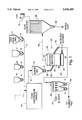
- FIG. 1 is a diagrammatic view of one embodiment of the apparatus used to practice the method of the present invention
- FIG. 2 is a diagrammatic view of another embodiment of the apparatus for carrying out the process of the present invention in which an embodiment of the feed preparation circuit is shown in greater detail.
- FIG. 3 is a graph that plots, inter alia, amounts of SO 2 emissions after the introduction of a cement kiln dust feed containing K 2 CO 3 as an add-on.
- cement forming raw materials are metered from a bin such as that illustrated at 5 in FIG. 1 onto a belt conveyer 6.
- the raw material may include some cement kiln dust (CKD) or, in fact, it may consist of all CKD.
- recycle product may be metered from a optional bin 7 to belt 6.
- the raw materials must be low in coloring elements, that is low in iron, manganese and chromium.
- Carbon bearing materials such as coal or coke may be added to the belt 6 from a bin 8 in an amount sufficient to bring the carbon content of the final raw material to the range of approximately 5% to 9% by weight carbon content.
- a source of potassium optionally in solid form, such as K 2 CO 3 or KOH, may be added in an amount suitable to effect a stoichiometric reaction with the SO 2 generated by the process and is metered onto belt 6 from bin 9.
- the apparatus may also optionally include additional bin or bins (not shown) which may be used for other additives if required by the process.
- feed preparation circuit 10 which may consist of dryers, mills, and/or pelletizers, etc. where the material is dried and sized for the fluidized bed. If it is desired to add the potassium in a solution form., such as in the form of a caustic waste, to the process it will be added during the feed preparation step via inlet 11.
- the add-on source of potassium may be added either in the form of a solid, a solution, or in both forms if desired.
- material is supplied from feed preparation circuit 10 via conduit 12 to a surge or storage bin 15.
- Material is metered out of the bin 15 and conveyed through line 16 to a fluidized bed reactor generally indicated at 20 for thermal processing the material to produce cement clinker.
- the fluidized bed reactor 20 includes a vessel having an inlet 22 for the dried and sized material from the feed preparation system 10.
- the vessel 20 is divided into an upper material chamber 23 and a lower plenum chamber 24 by means of a gas permeable grid 25 known in the art.
- the grid air distribution plate
- the size and quantity of these openings are designed based on particle sizing and calculated grid pressure drop requirements. A properly designed grid plate generates a pressure drop equal to approximately one half of the bed to ensure even air distribution.
- a positive displacement blower (not shown) supplies the pressurized air to the plenum.
- This air before entering the plenum, passes through an auxiliary air heater (not shown) required to bring the reactor up to the fuel ignition temperature (500° C.+).
- the volume of pressurized air supplied to the plenum generates a superficial fluidization velocity in the reaction zone in the range of eight to twelve feet per second. This maintains the bed material in a highly active fluidized state above the air distribution plate. Inadequate velocities result in reduced capacity and inter-particular adhesion, while extreme velocities lead to rapid particle degradation. After bed combustion is self-sustaining, fuel flow to the air heater is discontinued.
- Gas/oil injection is started to supplement coal combustion and to control the fluid bed temperature to obtain clinkering reactions; this temperature is typically in the range of 2350° to 2450° F. (1285°-1335° C.).
- Means are provided for supplying air under pressure of fluidizing gas to the plenum chamber 24 for passage upwardly through the grid 25 and a bed of feed material to thereby establish and maintain a fluidized bed 30 of nodules.
- Fuel in addition to that combined with the feed material is supplied through inlet 31 for supporting combustion within the fluidized bed 30.
- the amount of fuel added is sufficient to maintain the material within the fluidized bed at cement clinkering temperatures.
- carbon bearing material when carbon bearing material is incorporated in the original feed such carbon bearing material will be preferably mixed with cement raw meal in an amount sufficient to supply approximately 60 to 90% of the fuel requirements for thermal processing the feed material within the fluidized bed.
- product is discharged, such as by displacement through overflow conduit 45 to cooler 46.
- Material discharged from fluid bed reactor 20 is preferably discharged by displacement so that the rate of discharge of material depends upon the rate of feed of material to the vessel.
- Material retention time is typically on the order of 1 to 2 hours.
- Product discharged through conduit 45 is supplied to cooler means 46 where it is cooled, preferably by direct contact heat exchange with cooling air supplied from a source such as a blower 47. Air heated in the cooler means may be recycled to the process, such as by utilizing the thus heated cooling air for drying materials in the feed preparation circuit thereby reducing overall fuel consumption of the process.
- Product discharged from cooler 46 through outlet(s) 50 may, depending upon the raw material content and the temperature of bed 30, be either cement clinker or an intermediate product. If desired, cold water coils can be used for the final cooling step of the product in heat exchanger 46.
- Spend fluidizing gases may entrain a portion of the incoming feed and some fine product. Such gases will be discharged through an outlet 55 and eventually they may be supplied through conduit 58 to a high efficiency dust collector 59 wherein the solid material, typically in the form of an alkali dust, is separated and discharged at 60 and the gas is discharged to atmosphere through fan 61.
- SO 2 present in the off-gas stream will undergo reaction with a potassium oxide fume, which is formed by the heat decomposition of the potassium add-ons, to thereby form a potassium sulfate in the form of a fine white powder entrained in the gas stream.
- the potassium sulfate product will be separated from the gases in dust collector 59.
- FIG. 2 illustrates one embodiment of a portion of a feed preparation circuit of the present invention.
- raw material which as indicated may be CKD, plus coal/coke and other additives and, if desired, a solid source of potassium are metered through bins to a pug mill 101 for mixing of the solid materials with 10-15% water supplied via conduit 102. This water is required to react any freelime present, and is needed for pellet formation. If desired, a potassium solution may be added directly to the pug mill.
- the wet CKD blend in the pug mill is transferred via conduit 103 to pin-type pelletizer 104 where it is formed into small, uniform pellets, which are subsequently treated in rotating disc 105 where they are densifted and hardened and the pellet sizing is controlled.
- the pelletized material is screened (not shown), preferably to 4 ⁇ 20 mesh and sent to a dryer (not shown), such as a rotary drier, which may be optionally supplied with hot air from clinker cooler 46.
- a dryer such as a rotary drier, which may be optionally supplied with hot air from clinker cooler 46.
- exhaust gases from the dryer may be taken to a high efficiency dust collector (not shown), and the dust collected and recycled back to the pelletizing system along with undersized pellets from screening.
- Oversized pellets from screening may be crushed, such as in a mill (not shown), re-screened and dried.
- This representative feed preparation process most preferably generates a dry, approximately 4 ⁇ 20 mesh, pellet ( ⁇ 1% H 2 O) that is ideal for fluidized bed processing, although the actual size of the pellet feed utilized in the fluid bed process will depend on many factors including the particular needs of the individual practitioner of the invention. It has been found that some CKD samples will not pelletize properly without a binder. In these cases, approximately 2% to 5% portland cement is added as a binder to increase pellet strength and reduce particle degradation in the drying and calcining circuits. A curing period of several hours is required prior to drying of the pellets.
- a briquetting/compaction system may be instead utilized in the feed preparation circuit.
- a briquetting/compaction system requires a high-speed pug mill to blend CKD, coal and additives, including the potassium additives added according to the present invention.
- briquettes are crushed and screened, preferably to approximate 4 ⁇ 20 mesh with the--20 mesh fines recycled back to the briquetting unit.
- a drying circuit is typically not required as the only moisture present in the 4 ⁇ 20 mesh pellets is that which is present in the CKD prior to blending.
- an extruder may be utilized to prepare 1/2-1" diameter ⁇ 1-2" long wet extrusions from the blended CKD prepared by the pug mill. These extrusions require drying, followed by crushing and sizing.
- the extrusions are dried on a tray dryer to produced a hard nodule, which is then sent to storage for a period of 1 to 3 days for aging to allow the binder to increase the pellet or nodule strength.
- the stored or aged pellets may then be supplied to a crusher. While able to produce a suitable feed pellet, this process is at present the most energy intensive approach.
- the amount of potassium added to the system will depend on the amount of available potassium and sulfur present in the cement feed materials. Available sulfur will typically be in the form of CaSO 4 , the decomposition of which will generate the SO 2 in the system. Therefore the ideal molar ratios between the K 2 CO 3 add-on and the CaSO 4 present in the system will be 1:1, and the ideal molar ratio between the KOH add-on and the CaSO 4 present will be 2:1. Obviously, the amount of potassium added to the system will depend upon the composition of the original feed (ideally, a chemical analysis of the feed material should be made to determine the ideal amount of potassium to be added) and the needs of the practitioner of the invention.
- a 100 g dust sample contains the following compounds (assuming the chloride initially combines with the Na 2 O present):
- the graph of FIG. 3 illustrates the reduction in SO 2 emissions that occurred after introducing a cement kiln dust feed containing an addition of K 2 CO 3 .
- Phase I incorporated the processing of kiln dust without alkali addition, while Phase II was performed processing the same cement kiln dust feed with the addition of potassium carbonate.
- the reduction in SO 2 emissions was four fold following the introduction of the feed containing the potassium carbonate addition.
- the fluid bed system was effective in volatilizing most of the alkali present in the feed material to successfully generate a low alkali clinker while reducing SO 2 emissions, which, if significantly reduced according to the present process may result in the practitioner of the invention not requiring modifications to the calciner or off gas handling system to meet sulfur emission limitations.
- the alkali sulfate compounds formed are cooled to generate a fine, crystalline powder, which is collected at dust collector 59.
- this dust may be comprised of up to 90% potassium sulfate, making it suitable for marketing as a by-product.
Landscapes
- Chemical & Material Sciences (AREA)
- Engineering & Computer Science (AREA)
- Ceramic Engineering (AREA)
- Physics & Mathematics (AREA)
- Thermal Sciences (AREA)
- Materials Engineering (AREA)
- Structural Engineering (AREA)
- Organic Chemistry (AREA)
- Processing Of Solid Wastes (AREA)
Abstract
Description
Potassium Carbonate Source:
K.sub.2 CO.sub.3 →K.sub.2 O+CO.sub.2 ↑
2K.sub.2 O+2SO.sub.2 +O.sub.2 →2K.sub.2 SO.sub.4
Potassium Hydroxide Source:
2KOH→K.sub.2 O+H.sub.2 O↑
2K.sub.2 O+2SO.sub.2 +O.sub.2 →2K.sub.2 SO.sub.4
______________________________________
        CaO   40.42%
        K.sub.2 O
              1.41%
        Na.sub.2 O
              0.34%
        SO.sub.3
              4.98%
        Cl    0.52%
______________________________________
______________________________________
NaCl:           0.6435 g (0.0110 gmol)
KCl:            0.2758 g (0.2758 gmol)
Na.sub.2 SO.sub.4 :
                0.0000 g (0.0000 gmol)
K.sub.2 SO.sub.4 :
                2.2907 g (0.0132 gmol)
CaSO.sub.4 :    6.6912 g (0.0492 gmol)
CaO/CaCO.sub.3 :
                37.6700 g (0.6726 gmol CaO)
______________________________________
______________________________________
K.sub.2 CO.sub.3 Addition:
                   6.7994 g/100 g Feed
                   or
KOH Addition:      5.5202 g/100 g Feed
______________________________________
______________________________________
SiO.sub.2 :
           20.37%       C3S:    61.51
Al.sub.2 O.sub.3 :
           4.94%        C2S:    12.00
Fe.sub.2 O.sub.3 :
           3.17%        C3A:    7.73
CaO:       66.55%       C4AF:   9.65
MgO:       3.71%        LSF:    100.4
K.sub.2 O: 0.03%        HM:     2.34
Na.sub.2 O 0.04%        SR:     2.51
SO.sub.3 : 0.14%        AR:     1.56
P.sub.2 O.sub.5 :
           0.07%
TiO.sub.2 :
           0.29%
Mn.sub.2 O.sub.3 :
           0.07%
LOI.sub.@900°C. :
           0.40%
TOTAL:     99.83%
______________________________________
Claims (20)
Priority Applications (1)
| Application Number | Priority Date | Filing Date | Title |
|---|---|---|---|
| US08/482,927 US5556459A (en) | 1995-06-08 | 1995-06-08 | Method for the reduction of SO2 emissions as generated by the fluid bed cement process |
Applications Claiming Priority (1)
| Application Number | Priority Date | Filing Date | Title |
|---|---|---|---|
| US08/482,927 US5556459A (en) | 1995-06-08 | 1995-06-08 | Method for the reduction of SO2 emissions as generated by the fluid bed cement process |
Publications (1)
| Publication Number | Publication Date |
|---|---|
| US5556459A true US5556459A (en) | 1996-09-17 |
Family
ID=23917977
Family Applications (1)
| Application Number | Title | Priority Date | Filing Date |
|---|---|---|---|
| US08/482,927 Expired - Lifetime US5556459A (en) | 1995-06-08 | 1995-06-08 | Method for the reduction of SO2 emissions as generated by the fluid bed cement process |
Country Status (1)
| Country | Link |
|---|---|
| US (1) | US5556459A (en) |
Cited By (8)
| Publication number | Priority date | Publication date | Assignee | Title |
|---|---|---|---|---|
| US5800610A (en) * | 1994-11-11 | 1998-09-01 | F.L. Smidth & Co. A/S | Method for manufacturing cement clinker |
| US6142771A (en) * | 1997-12-02 | 2000-11-07 | Cement Petcoptimizer Company | Control of cement clinker production using high sulfur fuel in a Lelep-Lepol travelling grate rotary kiln by analysis of sulfur in the end product |
| US6183244B1 (en) | 1999-04-14 | 2001-02-06 | Cement Petcoptimizer Company | Control of cement clinker production in a wet process rotary kiln by analysis of sulfur in the end product |
| US6383283B1 (en) | 1997-12-02 | 2002-05-07 | Cement Petcoptimizer Company | Control of cement clinker production by analysis of sulfur in the end product |
| US20020083831A1 (en) * | 2000-12-29 | 2002-07-04 | Fcb Ciment Societe Anonyme | Process and device for eliminating harmful volatile elements, in particular chlorides and/or sulfates, contained in a stream of particle-laden fumes |
| WO2010016922A1 (en) * | 2008-08-07 | 2010-02-11 | Flsmidth A/S | Apparatus and method for reducing emissions resulting from raw meal grinding |
| US20110159449A1 (en) * | 2009-12-31 | 2011-06-30 | Flsmidth A/S | Integrated Material Cooler and Heat Recovery Exchanger Apparatus and Process |
| CN112299713A (en) * | 2020-11-13 | 2021-02-02 | 郑州市华源玻璃制品有限公司 | Production process of beer bottle |
Citations (6)
| Publication number | Priority date | Publication date | Assignee | Title |
|---|---|---|---|---|
| US4001030A (en) * | 1974-02-28 | 1977-01-04 | The Associated Portland Cement Manufacturers Limited | Treatment of waste products from portland cement manufacture |
| US4173487A (en) * | 1974-10-07 | 1979-11-06 | Fuller Company | Process for treating cement plant dust catch |
| US4179302A (en) * | 1976-08-20 | 1979-12-18 | Tashkentsky Nauchno-Issledovatelsky I Proektny Institut Stroitelnykh Materialov "Niistromproekt" | Raw mixture for the production of cement clinker |
| US4469664A (en) * | 1982-04-28 | 1984-09-04 | Klockner-Humboldt-Deutz Ag | Method for reducing the concentration of sulfur compounds in a system for calcining fine grained materials |
| US4584022A (en) * | 1984-08-27 | 1986-04-22 | Fuller Company | Cement plant dust recovery system |
| US4708855A (en) * | 1985-11-07 | 1987-11-24 | Passanaquoddy Tribe | Method and system for exhaust gas stream scrubbing |
-
1995
- 1995-06-08 US US08/482,927 patent/US5556459A/en not_active Expired - Lifetime
Patent Citations (6)
| Publication number | Priority date | Publication date | Assignee | Title |
|---|---|---|---|---|
| US4001030A (en) * | 1974-02-28 | 1977-01-04 | The Associated Portland Cement Manufacturers Limited | Treatment of waste products from portland cement manufacture |
| US4173487A (en) * | 1974-10-07 | 1979-11-06 | Fuller Company | Process for treating cement plant dust catch |
| US4179302A (en) * | 1976-08-20 | 1979-12-18 | Tashkentsky Nauchno-Issledovatelsky I Proektny Institut Stroitelnykh Materialov "Niistromproekt" | Raw mixture for the production of cement clinker |
| US4469664A (en) * | 1982-04-28 | 1984-09-04 | Klockner-Humboldt-Deutz Ag | Method for reducing the concentration of sulfur compounds in a system for calcining fine grained materials |
| US4584022A (en) * | 1984-08-27 | 1986-04-22 | Fuller Company | Cement plant dust recovery system |
| US4708855A (en) * | 1985-11-07 | 1987-11-24 | Passanaquoddy Tribe | Method and system for exhaust gas stream scrubbing |
Cited By (12)
| Publication number | Priority date | Publication date | Assignee | Title |
|---|---|---|---|---|
| US5800610A (en) * | 1994-11-11 | 1998-09-01 | F.L. Smidth & Co. A/S | Method for manufacturing cement clinker |
| US6142771A (en) * | 1997-12-02 | 2000-11-07 | Cement Petcoptimizer Company | Control of cement clinker production using high sulfur fuel in a Lelep-Lepol travelling grate rotary kiln by analysis of sulfur in the end product |
| US6383283B1 (en) | 1997-12-02 | 2002-05-07 | Cement Petcoptimizer Company | Control of cement clinker production by analysis of sulfur in the end product |
| US6183244B1 (en) | 1999-04-14 | 2001-02-06 | Cement Petcoptimizer Company | Control of cement clinker production in a wet process rotary kiln by analysis of sulfur in the end product |
| US20020083831A1 (en) * | 2000-12-29 | 2002-07-04 | Fcb Ciment Societe Anonyme | Process and device for eliminating harmful volatile elements, in particular chlorides and/or sulfates, contained in a stream of particle-laden fumes |
| US6755906B2 (en) * | 2000-12-29 | 2004-06-29 | Fcb Ciment, Societe Anonyme | Process and device for eliminating harmful volatile elements, in particular chlorides and/or sulfates, contained in a stream of particle-laden fumes |
| WO2010016922A1 (en) * | 2008-08-07 | 2010-02-11 | Flsmidth A/S | Apparatus and method for reducing emissions resulting from raw meal grinding |
| RU2504427C2 (en) * | 2008-08-07 | 2014-01-20 | Эф-Эл-Смидт А/С | Device and method of reduction of emissions in grinding raw stock mix |
| EP2321036A4 (en) * | 2008-08-07 | 2014-03-26 | Smidth As F L | APPARATUS AND METHOD FOR REDUCING EMISSIONS RESULTING FROM MILLING OF RAW FLOUR |
| CN102149447B (en) * | 2008-08-07 | 2015-09-16 | Fl史密斯公司 | For reducing the apparatus and method of emissions resulting from raw meal grinding |
| US20110159449A1 (en) * | 2009-12-31 | 2011-06-30 | Flsmidth A/S | Integrated Material Cooler and Heat Recovery Exchanger Apparatus and Process |
| CN112299713A (en) * | 2020-11-13 | 2021-02-02 | 郑州市华源玻璃制品有限公司 | Production process of beer bottle |
Similar Documents
| Publication | Publication Date | Title |
|---|---|---|
| US5049198A (en) | Calcium sulfate process for the coproduction of Portland cement clinker and concentrated sulfur dioxide adequate to manufacture sulfuric acid | |
| US7387662B2 (en) | Method and device for separating gaseous pollutants from hot process gases by absorption and a mixer for moistening particulate dust | |
| US4600438A (en) | Co-production of cementitious products | |
| GB2118924A (en) | Method of and apparatus for reducing the sulphur circulation and/or the so2 emission in a plant for burning fine-grained material | |
| CZ287497A3 (en) | Process and apparatus for utilization of blast furnace slag when producing cement clinker | |
| US5976243A (en) | Process for producing cement clinker containing blast furnace slag | |
| CZ232097A3 (en) | Process for improving powders occurred during reduction of iron ore | |
| US4682948A (en) | Method and apparatus for producing cement clinker including white cement | |
| US5556459A (en) | Method for the reduction of SO2 emissions as generated by the fluid bed cement process | |
| US4913068A (en) | Method for improving utilization of sulphur-absorbent containing calcium in a power plant and equipment for performing the method | |
| JP6696053B2 (en) | Apparatus and method for treating organic sludge | |
| US4584022A (en) | Cement plant dust recovery system | |
| US5137704A (en) | Process of decreasing nox content of exhaust gases | |
| US5800610A (en) | Method for manufacturing cement clinker | |
| US5782973A (en) | Cement dust recovery system | |
| CN107108211A (en) | The increased phosphorus pentoxide preparation method of aggregation block compressive strength and system | |
| US4321239A (en) | Method of thermal treatment of a carbonate suspension | |
| US4404032A (en) | Process for producing cement clinker | |
| CN212610314U (en) | Copper-nickel-containing solid hazardous waste sintering system | |
| WO2012025852A1 (en) | Low emission production process of scm | |
| CA1221674A (en) | Desulfurizing method for combustion exhaust gases | |
| US3998596A (en) | Apparatus for treating by-product gypsum to be used as an inhibitor for setting of cement | |
| SU1664774A1 (en) | Method of producing granulated lime fertilizers | |
| AU683774C (en) | Method for manufacturing cement clinker in a stationary burning reactor | |
| CA1239153A (en) | Method and apparatus for producing cement clinker including white cement |
Legal Events
| Date | Code | Title | Description |
|---|---|---|---|
| AS | Assignment |
Owner name: DEJOSEPH, DANIEL, PENNSYLVANIA Free format text: ASSIGNMENT OF ASSIGNORS INTEREST;ASSIGNORS:COHEN, SIDNEY M.;PROKESCH, MICHAEL E.;REEL/FRAME:007563/0481 Effective date: 19950602 |
|
| REMI | Maintenance fee reminder mailed | ||
| FPAY | Fee payment |
Year of fee payment: 4 |
|
| SULP | Surcharge for late payment | ||
| REMI | Maintenance fee reminder mailed | ||
| FPAY | Fee payment |
Year of fee payment: 8 |
|
| SULP | Surcharge for late payment |
Year of fee payment: 7 |
|
| FEPP | Fee payment procedure |
Free format text: PETITION RELATED TO MAINTENANCE FEES FILED (ORIGINAL EVENT CODE: PMFP); ENTITY STATUS OF PATENT OWNER: LARGE ENTITY |
|
| REMI | Maintenance fee reminder mailed | ||
| REIN | Reinstatement after maintenance fee payment confirmed | ||
| FP | Lapsed due to failure to pay maintenance fee |
Effective date: 20080917 |
|
| FEPP | Fee payment procedure |
Free format text: PETITION RELATED TO MAINTENANCE FEES GRANTED (ORIGINAL EVENT CODE: PMFG); ENTITY STATUS OF PATENT OWNER: LARGE ENTITY |
|
| FPAY | Fee payment |
Year of fee payment: 12 |
|
| SULP | Surcharge for late payment | ||
| PRDP | Patent reinstated due to the acceptance of a late maintenance fee |
Effective date: 20090213 |
|
| STCF | Information on status: patent grant |
Free format text: PATENTED CASE |