US5551889A - Low profile insulation displacement connection programmable block and wire to board connector - Google Patents
Low profile insulation displacement connection programmable block and wire to board connector Download PDFInfo
- Publication number
- US5551889A US5551889A US08/176,073 US17607393A US5551889A US 5551889 A US5551889 A US 5551889A US 17607393 A US17607393 A US 17607393A US 5551889 A US5551889 A US 5551889A
- Authority
- US
- United States
- Prior art keywords
- wire
- terminating cover
- block
- contact
- wires
- Prior art date
- Legal status (The legal status is an assumption and is not a legal conclusion. Google has not performed a legal analysis and makes no representation as to the accuracy of the status listed.)
- Expired - Fee Related
Links
Images


Classifications
-
- H—ELECTRICITY
- H01—ELECTRIC ELEMENTS
- H01R—ELECTRICALLY-CONDUCTIVE CONNECTIONS; STRUCTURAL ASSOCIATIONS OF A PLURALITY OF MUTUALLY-INSULATED ELECTRICAL CONNECTING ELEMENTS; COUPLING DEVICES; CURRENT COLLECTORS
- H01R4/00—Electrically-conductive connections between two or more conductive members in direct contact, i.e. touching one another; Means for effecting or maintaining such contact; Electrically-conductive connections having two or more spaced connecting locations for conductors and using contact members penetrating insulation
- H01R4/24—Connections using contact members penetrating or cutting insulation or cable strands
- H01R4/2416—Connections using contact members penetrating or cutting insulation or cable strands the contact members having insulation-cutting edges, e.g. of tuning fork type
- H01R4/2445—Connections using contact members penetrating or cutting insulation or cable strands the contact members having insulation-cutting edges, e.g. of tuning fork type the contact members having additional means acting on the insulation or the wire, e.g. additional insulation penetrating means, strain relief means or wire cutting knives
- H01R4/245—Connections using contact members penetrating or cutting insulation or cable strands the contact members having insulation-cutting edges, e.g. of tuning fork type the contact members having additional means acting on the insulation or the wire, e.g. additional insulation penetrating means, strain relief means or wire cutting knives the additional means having two or more slotted flat portions
-
- H—ELECTRICITY
- H01—ELECTRIC ELEMENTS
- H01R—ELECTRICALLY-CONDUCTIVE CONNECTIONS; STRUCTURAL ASSOCIATIONS OF A PLURALITY OF MUTUALLY-INSULATED ELECTRICAL CONNECTING ELEMENTS; COUPLING DEVICES; CURRENT COLLECTORS
- H01R29/00—Coupling parts for selective co-operation with a counterpart in different ways to establish different circuits, e.g. for voltage selection, for series-parallel selection, programmable connectors
-
- H—ELECTRICITY
- H01—ELECTRIC ELEMENTS
- H01R—ELECTRICALLY-CONDUCTIVE CONNECTIONS; STRUCTURAL ASSOCIATIONS OF A PLURALITY OF MUTUALLY-INSULATED ELECTRICAL CONNECTING ELEMENTS; COUPLING DEVICES; CURRENT COLLECTORS
- H01R31/00—Coupling parts supported only by co-operation with counterpart
- H01R31/08—Short-circuiting members for bridging contacts in a counterpart
-
- H—ELECTRICITY
- H01—ELECTRIC ELEMENTS
- H01R—ELECTRICALLY-CONDUCTIVE CONNECTIONS; STRUCTURAL ASSOCIATIONS OF A PLURALITY OF MUTUALLY-INSULATED ELECTRICAL CONNECTING ELEMENTS; COUPLING DEVICES; CURRENT COLLECTORS
- H01R4/00—Electrically-conductive connections between two or more conductive members in direct contact, i.e. touching one another; Means for effecting or maintaining such contact; Electrically-conductive connections having two or more spaced connecting locations for conductors and using contact members penetrating insulation
- H01R4/24—Connections using contact members penetrating or cutting insulation or cable strands
- H01R4/2416—Connections using contact members penetrating or cutting insulation or cable strands the contact members having insulation-cutting edges, e.g. of tuning fork type
- H01R4/242—Connections using contact members penetrating or cutting insulation or cable strands the contact members having insulation-cutting edges, e.g. of tuning fork type the contact members being plates having a single slot
- H01R4/2425—Flat plates, e.g. multi-layered flat plates
- H01R4/2429—Flat plates, e.g. multi-layered flat plates mounted in an insulating base
- H01R4/2433—Flat plates, e.g. multi-layered flat plates mounted in an insulating base one part of the base being movable to push the cable into the slot
Definitions
- Headers and shunts are commonly used on printed circuit boards for programming a device.
- the present invention is an improved low cost device for providing a programmable electrical insulation displacement contact block and/or wire to board connector, having a low profile.
- Devices such as headers and shunts, dip switches and hand soldering have been used to provide programmability for devices such as disk drives, garage door openers or theft deterrent systems. Such a device is assembled in a standard form and then prior to shipment needs to be programmed for a specific application or keyed with a specific code. Some of these devices are also programmed by the customer after shipment by orienting dip switches, placing shunts or soldering jumpers to provide a security code.
- a header is soldered or attached to a printed circuit board having multiple pairs of contacts protruding therefrom.
- shunts are placed across specific pairs of contacts in order to short the connector across the pairs of contacts.
- the shunts are sometimes difficult to use or are expensive and may have too high a profile. As many devices become more and more miniaturized, lower and lower profile connectors are required.
- a principal object of this invention is to provide an insulation displacement contact (IDC) programmable block, including at least one cavity having at least one contact member to receive an electrical wire.
- the IDC block further includes a contact having knife-like arms which penetrate the insulation surrounding a wire upon insertion in the cavity. The contact provides electrical contact between the wire and the contact and a printed circuit board.
- the IDC block includes contacts having contact tails to allow mounting of the IDC block to a printed circuit board.
- a terminating cover may be provided having regularly spaced passages for receiving electrical wires spaced corresponding to the channels of the IDC block. The terminating cover when mated with the IDC block, terminates the wires automatically.
- the terminating cover or the IDC block may be previously supplied with wires for preprogramming or a specific wire or wires could be removed from the supplied wired block or terminating cover to allow customer programming of the IDC block.
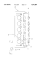
- FIG. 1 s a perspective view of an IDC programmable block and terminating cover
- FIG. 2 is a front elevation view of an IDC block having a terminating cover staged above the terminating block;
- FIG. 3 s a side elevation view of an IDC block having a terminating cover staged above the IDC block;
- FIG. 4 is a side elevation view of the IDC block having a terminating cover fully mated to the IDC block;
- FIG. 5 is a front elevation view of an IDC block having a terminating cover fully mated to the IDC block;
- FIG. 6 is an alternative embodiment of an IDC block and terminating cover having through board contact mounting
- FIG. 7 is an IDC block having a further alternative configuration having cover tape attached to the IDC block.
- FIG. 1 illustrates an IDC block 10 having five cavities, however, this invention is not limited to a block having only five cavities but may have any number of cavities and contacts disposed therein.
- the contacts 12 in the preferred embodiment are U-shaped and have upright arms 13,14 and base 15. Protruding from the contact base 15 through the insulator 18 is a contact tail 16.
- FIG. 1 shows a configuration of the contact 12 providing for surface mounting to a printed circuit board, wherein the contact tail 16 is parallel to the bottom surface 20 of the block 10. In another embodiment, the contact tail may also be perpendicular to the bottom 20 of the block 10 to provide through board mounting of the block on a printed circuit board (see FIG. 6). Any contact configuration which allows mounting of the block on a printed circuit board is encompassed by this invention.
- the insulator 18 of the block 10 is made of a polymer material such as polyester.
- the height of the IDC block 10 would be approximately 0.100 inches to 0.150 inches. This design allows for a miniaturized IDC block which will take up the smallest amount of space on a printed circuit board.
- Other important dimensions of a preferred embodiment of the IDC block include contact spacings on 2 mm(0.079 inches) and 2.54 mm(0.100 inches).
- the programmable block invention may function alone, or it may be used in combination with a terminating cover 30.
- the programmable block 10 as shown in FIG. 1 may function alone by placing wires by hand into the cavities 11 and IDC'ing the wires to the block 10 to provide a programmed block for a security code or some other purpose. Any wire may be inserted in the IDC block 10.
- jumper wire 9 may be used. The jumper wire 9 does not connect to an external device but is placed across pairs of contacts 12 in order to short the IDC block 10 across the pairs of contacts in the cavity 8. The jumper wire 9 is used for programming the IDC block 10.
- color-coded wires may be preinserted in the cavities 11 and then later removed by the customer to provide the specific combination of programming required by removing some or all of the wires.
- these programming functions may also be accomplished by inserting jumper wires 9 into terminating cover 30.
- the present invention allows for mass termination of wires without use of special tools, complicated methods, or time-consuming methods such as soldering.
- a terminating cover 30 may also be used to provide simple termination of wires from an external unit inserted in the cavities 11 for wire to board termination.
- the terminating cover 30 includes a top 31 and two sides 32,33. Uniformly spaced along the sides 32,33 are holes 34 for receiving electrical wires. Any wire may be inserted in the cover 30.
- device wire 35 which connects to an external device is used for termination of the device wire 35 to a board.
- the device wires 35 include insulation 36 surrounding a metal wire core 37.
- Corresponding to the holes 34 inside of the terminating cover 30 are support blocks 38. Upon insertion of the device wire 35 through hole 34 into the terminating cover 30 the device wire 35 will rest against support block 38.
- the support block 38 Upon mating of the terminating cover 30 with the IDC block 10 the support block 38 will terminate and retain the device wire 35 in a taught position.
- the contacts 12 pierce the insulation 36 and make electrical contact with the metal wire core 37.
- the support blocks 38 are separated a distance from the walls 32,33 of the terminating cover 30 so that upon mating with the IDC block 10 the contact arms 13,14 may pierce through and above the device wire 35 without making contact with the support block 38 or the top 31.
- the terminating cover 30 in a preferred embodiment is configured so that its width is greater than the width of the IDC block 10 so that the terminating cover 30 can easily mate with and fit over the IDC block 10.
- FIG. 2 shows a front view of the combination IDC block 10 and terminating cover 30.
- This drawings shows the terminating cover 30 staged over the top the IDC block 10 in a partially mated configuration. It can be seen that the holes 34 align with the cavities 11 which contain contacts 12 having arms 13,14. Contact tail 16 is shown in FIG. 2 having a surface mount configuration.
- FIG. 3 shows a side view of the IDC block 10 having a terminating cover 30 partially mated in a staged position above the IDC block 10.
- Device wire 35 is shown inserted in hole 34.
- the device wire 35 is illustrated cut-away at the end, but actually continues and connects to an external device.
- FIG. 3 also shows the terminating cover 30 partially cut-away so that the hole 34 containing device wire 35 is exposed.
- Contacts 12 are shown having a surface mount configuration wherein contact tail 16 can be mounted to a solder pad of a printed circuit board (not shown) and mounted thereto via infrared soldering or other manner. It can be seen in FIG. 3 that as the terminating cover 30 is pushed downwardly in the direction of arrow 39 the device wire 35 will come into contact with metal contacts 12.
- FIG. 4 shows the terminating cover 30 fully mated with IDC block 10.
- the contacts 12 have penetrated device wire 35 providing for wire to board termination.
- the device wire 35 may also be IDC'd directly to the IDC block 10 without use of the terminating cover 30.
- the contacts in a preferred embodiment are formed with knife-like edges so that they may easily penetrate the insulation 36 of device wire 35.
- FIG. 5 shows a front elevation of the IDC block 10 and terminating cover 30 in a fully mated configuration. It can be seen that contacts 12 have a narrow gap 17 so that when device wire 35 is inserted therein the arms of the contact 12 make electrical contact with the metal wire core 37 of device wire 35.
- FIG. 6 shows an alternative embodiment of the present invention having through board contacts 40. Also shown are mounting pegs 41. This configuration allows the IDC block 10 and terminating cover 30 combination to be mounted to a printed circuit board by insertion of the through board contact tails 40 into a printed circuit board and soldered thereto. The mounting pegs 40 are also inserted in a printed circuit board to provide for proper placement of the IDC block on the printed circuit board and to maintain stable placement thereon. Other usage of mounting pegs is with blocks having surface mount tails.
- FIG. 7 Another alternative embodiment is shown in FIG. 7 wherein the IDC block 10 includes a cover tape 45.
- the cover tape 45 is temporarily adhered to the top surface of the IDC block 10 to allow for robotic assembly such as vacuum pick-and-placement of the IDC block 10 onto a printed circuit board.
- the cover tape 45 may be removed after the IDC block 10 is robotically placed onto the printed circuit board and mounted thereto, to allow for mating with the terminating cover.
Landscapes
- Multi-Conductor Connections (AREA)
Abstract
A wire to board connector is provided having an insulation block including cavities for insulation displacement contact which allow for programmability by insertion of wires in a predetermined orientation in cavities having contacts having contact tails for mounting on a circuit board. A terminating cover may also be provided for receiving wires therein and providing automatic termination when the terminating cover is mated with the insulation block whereby the wires inserted in the terminating cover are terminated in the corresponding cavities of the insulation block.
Description
Headers and shunts are commonly used on printed circuit boards for programming a device. The present invention is an improved low cost device for providing a programmable electrical insulation displacement contact block and/or wire to board connector, having a low profile.
Devices such as headers and shunts, dip switches and hand soldering have been used to provide programmability for devices such as disk drives, garage door openers or theft deterrent systems. Such a device is assembled in a standard form and then prior to shipment needs to be programmed for a specific application or keyed with a specific code. Some of these devices are also programmed by the customer after shipment by orienting dip switches, placing shunts or soldering jumpers to provide a security code.
In a typical device, for illustration, a header is soldered or attached to a printed circuit board having multiple pairs of contacts protruding therefrom. In order to program the device, shunts are placed across specific pairs of contacts in order to short the connector across the pairs of contacts. The shunts are sometimes difficult to use or are expensive and may have too high a profile. As many devices become more and more miniaturized, lower and lower profile connectors are required.
Therefore, it is an object of the present invention to provide a programmable type shunt connector having a low profile.
It is a further objective of the present invention to provide a shunt type connector which may be manufactured at a low cost.
It is another object of the present invention to provide an insulation displacement contact and/or wire to board connection which is quickly and simply accomplished.
It is a further object of the present invention to provide a wire to board connector having a low profile.
It is another object of the present invention to provide multiple insulation displacement contact terminals in a unitary block.
A principal object of this invention is to provide an insulation displacement contact (IDC) programmable block, including at least one cavity having at least one contact member to receive an electrical wire. The IDC block further includes a contact having knife-like arms which penetrate the insulation surrounding a wire upon insertion in the cavity. The contact provides electrical contact between the wire and the contact and a printed circuit board. The IDC block includes contacts having contact tails to allow mounting of the IDC block to a printed circuit board. A terminating cover may be provided having regularly spaced passages for receiving electrical wires spaced corresponding to the channels of the IDC block. The terminating cover when mated with the IDC block, terminates the wires automatically. The terminating cover or the IDC block may be previously supplied with wires for preprogramming or a specific wire or wires could be removed from the supplied wired block or terminating cover to allow customer programming of the IDC block.
These and other features of the invention are set forth below in the following detailed description of the presently preferred embodiments.
There is shown in the drawings a presently preferred embodiment of the present invention, wherein like numerals in the various figures pertain to like elements, and wherein:
FIG. 1 s a perspective view of an IDC programmable block and terminating cover;
FIG. 2 is a front elevation view of an IDC block having a terminating cover staged above the terminating block;
FIG. 3 s a side elevation view of an IDC block having a terminating cover staged above the IDC block;
FIG. 4 is a side elevation view of the IDC block having a terminating cover fully mated to the IDC block;
FIG. 5 is a front elevation view of an IDC block having a terminating cover fully mated to the IDC block;
FIG. 6 is an alternative embodiment of an IDC block and terminating cover having through board contact mounting; and
FIG. 7 is an IDC block having a further alternative configuration having cover tape attached to the IDC block.
The present invention relates to an IDC block 10 and having cavities 11 having contacts 12 disposed therein. FIG. 1 illustrates an IDC block 10 having five cavities, however, this invention is not limited to a block having only five cavities but may have any number of cavities and contacts disposed therein. The contacts 12 in the preferred embodiment are U-shaped and have upright arms 13,14 and base 15. Protruding from the contact base 15 through the insulator 18 is a contact tail 16. FIG. 1 shows a configuration of the contact 12 providing for surface mounting to a printed circuit board, wherein the contact tail 16 is parallel to the bottom surface 20 of the block 10. In another embodiment, the contact tail may also be perpendicular to the bottom 20 of the block 10 to provide through board mounting of the block on a printed circuit board (see FIG. 6). Any contact configuration which allows mounting of the block on a printed circuit board is encompassed by this invention.
In a preferred embodiment, the insulator 18 of the block 10 is made of a polymer material such as polyester. In a preferred embodiment, the height of the IDC block 10 would be approximately 0.100 inches to 0.150 inches. This design allows for a miniaturized IDC block which will take up the smallest amount of space on a printed circuit board. Other important dimensions of a preferred embodiment of the IDC block include contact spacings on 2 mm(0.079 inches) and 2.54 mm(0.100 inches).
The programmable block invention may function alone, or it may be used in combination with a terminating cover 30. The programmable block 10 as shown in FIG. 1 may function alone by placing wires by hand into the cavities 11 and IDC'ing the wires to the block 10 to provide a programmed block for a security code or some other purpose. Any wire may be inserted in the IDC block 10. In a preferred embodiment, jumper wire 9 may be used. The jumper wire 9 does not connect to an external device but is placed across pairs of contacts 12 in order to short the IDC block 10 across the pairs of contacts in the cavity 8. The jumper wire 9 is used for programming the IDC block 10. In an alternative embodiment, color-coded wires may be preinserted in the cavities 11 and then later removed by the customer to provide the specific combination of programming required by removing some or all of the wires. However, these programming functions may also be accomplished by inserting jumper wires 9 into terminating cover 30. The present invention allows for mass termination of wires without use of special tools, complicated methods, or time-consuming methods such as soldering.
As shown in FIG. 1, a terminating cover 30 may also be used to provide simple termination of wires from an external unit inserted in the cavities 11 for wire to board termination. The terminating cover 30 includes a top 31 and two sides 32,33. Uniformly spaced along the sides 32,33 are holes 34 for receiving electrical wires. Any wire may be inserted in the cover 30. In a preferred embodiment device wire 35 which connects to an external device is used for termination of the device wire 35 to a board. The device wires 35 include insulation 36 surrounding a metal wire core 37. Corresponding to the holes 34 inside of the terminating cover 30 are support blocks 38. Upon insertion of the device wire 35 through hole 34 into the terminating cover 30 the device wire 35 will rest against support block 38. Upon mating of the terminating cover 30 with the IDC block 10 the support block 38 will terminate and retain the device wire 35 in a taught position. Upon mating of the terminating cover 30 with the IDC block 10, the contacts 12 pierce the insulation 36 and make electrical contact with the metal wire core 37. The support blocks 38 are separated a distance from the walls 32,33 of the terminating cover 30 so that upon mating with the IDC block 10 the contact arms 13,14 may pierce through and above the device wire 35 without making contact with the support block 38 or the top 31. The terminating cover 30 in a preferred embodiment is configured so that its width is greater than the width of the IDC block 10 so that the terminating cover 30 can easily mate with and fit over the IDC block 10.
FIG. 2 shows a front view of the combination IDC block 10 and terminating cover 30. This drawings shows the terminating cover 30 staged over the top the IDC block 10 in a partially mated configuration. It can be seen that the holes 34 align with the cavities 11 which contain contacts 12 having arms 13,14. Contact tail 16 is shown in FIG. 2 having a surface mount configuration.
FIG. 3 shows a side view of the IDC block 10 having a terminating cover 30 partially mated in a staged position above the IDC block 10. Device wire 35 is shown inserted in hole 34. The device wire 35 is illustrated cut-away at the end, but actually continues and connects to an external device. FIG. 3 also shows the terminating cover 30 partially cut-away so that the hole 34 containing device wire 35 is exposed. Contacts 12 are shown having a surface mount configuration wherein contact tail 16 can be mounted to a solder pad of a printed circuit board (not shown) and mounted thereto via infrared soldering or other manner. It can be seen in FIG. 3 that as the terminating cover 30 is pushed downwardly in the direction of arrow 39 the device wire 35 will come into contact with metal contacts 12.
FIG. 4 shows the terminating cover 30 fully mated with IDC block 10. In the fully mated configuration, it can be seen that the contacts 12 have penetrated device wire 35 providing for wire to board termination. However, the device wire 35 may also be IDC'd directly to the IDC block 10 without use of the terminating cover 30. The contacts in a preferred embodiment are formed with knife-like edges so that they may easily penetrate the insulation 36 of device wire 35.
FIG. 5 shows a front elevation of the IDC block 10 and terminating cover 30 in a fully mated configuration. It can be seen that contacts 12 have a narrow gap 17 so that when device wire 35 is inserted therein the arms of the contact 12 make electrical contact with the metal wire core 37 of device wire 35.
FIG. 6 shows an alternative embodiment of the present invention having through board contacts 40. Also shown are mounting pegs 41. This configuration allows the IDC block 10 and terminating cover 30 combination to be mounted to a printed circuit board by insertion of the through board contact tails 40 into a printed circuit board and soldered thereto. The mounting pegs 40 are also inserted in a printed circuit board to provide for proper placement of the IDC block on the printed circuit board and to maintain stable placement thereon. Other usage of mounting pegs is with blocks having surface mount tails.
Another alternative embodiment is shown in FIG. 7 wherein the IDC block 10 includes a cover tape 45. The cover tape 45 is temporarily adhered to the top surface of the IDC block 10 to allow for robotic assembly such as vacuum pick-and-placement of the IDC block 10 onto a printed circuit board. The cover tape 45 may be removed after the IDC block 10 is robotically placed onto the printed circuit board and mounted thereto, to allow for mating with the terminating cover.
The description above has been offered for illustrative purposes only, and it is not intended to limit the scope of the invention of this application which is defined in the following claims.
Claims (8)
1. A wire to board connector providing insulation displacement contact (IDC) connection and programmability comprising:
an insulation block including a bottom surface and at least one cavity having at least a pair of IDC contacts mounted in said cavity for receiving a wire having insulation that is pierced by knife-like edges of the contacts, said contacts having two arms each having, length and the cavity surrounding the entire said length of the contact arms and surface mount contact tails protruding parallel to said bottom surface for mounting on a circuit board.
2. The connector of claim 1 comprising:
a terminating cover including parallel sides having at least one pair of holes, said holes for receiving said wire and correspondingly positioned to said cavity; said terminating cover matable with said insulation block.
3. The connector of claim 1 wherein said insulation block has a height of less than 0.150 inches.
4. The connector of claim 2 wherein said insulation block includes multiple cavities having a contact having two arms;
said terminating cover includes multiple holes oriented along said sides to receive said wires therein; said holes corresponding to said cavities; said wires being pierced by said arms upon mating of said insulation block with said terminating cover.
5. The connector of claim 4 wherein said terminating cover includes multiple support blocks adjacent said parallel sides; said support blocks abutting said wires and providing support of said wires upon mating of said insulation block with said terminating cover whereby said contact pushes said wire against said support block and pierces said wire.
6. A wire to board connector providing insulation displacement contact (IDC) connection and programmability comprising:
an insulation block including a bottom surface and multiple cavities having at least a pair of IDC contacts mounted in said cavities for receiving a wire having insulation that is pierced by knife-like edges of the contacts, said contacts having two arms each having a length and the cavity surrounding the entire said length of said contact arms and a surface mount contact tail protruding parallel to said bottom surface for mounting on a circuit board;
a terminating cover including parallel sides having multiple pairs of holes, said holes for receiving said wire and correspondingly positioned to said cavity, said terminating cover matable with said insulation block and said wires being pierced by said arms upon mating of said insulation block with said terminating cover.
7. The connector of claim 6 wherein said wire includes a device wire.
8. The connector of claim 6 wherein said terminating cover includes multiple support blocks adjacent said parallel sides; said support blocks abutting said wires and providing support of said wires upon mating of said insulation block with said terminating cover whereby said contact pushes said wire against said support block and pierces said wire.
Priority Applications (1)
| Application Number | Priority Date | Filing Date | Title |
|---|---|---|---|
| US08/176,073 US5551889A (en) | 1993-12-30 | 1993-12-30 | Low profile insulation displacement connection programmable block and wire to board connector |
Applications Claiming Priority (1)
| Application Number | Priority Date | Filing Date | Title |
|---|---|---|---|
| US08/176,073 US5551889A (en) | 1993-12-30 | 1993-12-30 | Low profile insulation displacement connection programmable block and wire to board connector |
Publications (1)
| Publication Number | Publication Date |
|---|---|
| US5551889A true US5551889A (en) | 1996-09-03 |
Family
ID=22642870
Family Applications (1)
| Application Number | Title | Priority Date | Filing Date |
|---|---|---|---|
| US08/176,073 Expired - Fee Related US5551889A (en) | 1993-12-30 | 1993-12-30 | Low profile insulation displacement connection programmable block and wire to board connector |
Country Status (1)
| Country | Link |
|---|---|
| US (1) | US5551889A (en) |
Cited By (35)
| Publication number | Priority date | Publication date | Assignee | Title |
|---|---|---|---|---|
| USD396475S (en) | 1996-10-04 | 1998-07-28 | Reltec Corporation | Terminal block housing |
| USD414466S (en) | 1998-05-06 | 1999-09-28 | Reltec Corporation | Terminal block housing |
| US6050845A (en) * | 1997-11-20 | 2000-04-18 | The Whitaker Corporation | Electrical connector for terminating insulated conductors |
| US6074240A (en) * | 1996-10-16 | 2000-06-13 | Marconi Communications Inc. | Terminal block |
| WO2002086367A3 (en) * | 2001-04-20 | 2003-03-27 | Woodhead Ind Inc | Field-attachable connector |
| WO2003047040A1 (en) * | 2001-11-21 | 2003-06-05 | Woodhead Industries, Inc. | Molded electrical connector |
| US20040053532A1 (en) * | 2002-09-12 | 2004-03-18 | Jones Dennis B. | Low crosstalk insulation displacement connector for terminating cable to circuit board |
| US20060057884A1 (en) * | 2004-09-15 | 2006-03-16 | Xavier Fasce | Connector assembly for housing insulation displacement elements |
| US20060089040A1 (en) * | 2004-09-15 | 2006-04-27 | 3M Innovative Properties Company | Cap configured to removably connect to an insulation displacement connector block |
| US20060160404A1 (en) * | 2004-09-15 | 2006-07-20 | Alarcon Sergio A | Connector assembly for housing insulation displacement elements |
| USD530679S1 (en) * | 2005-08-31 | 2006-10-24 | Hon Hai Precision Ind. Co., Ltd. | Electrical connector |
| US7134903B1 (en) * | 2005-10-12 | 2006-11-14 | Lear Corporation | Insulation displacement connection |
| US20070047732A1 (en) * | 2005-08-26 | 2007-03-01 | Bryan Kennedy | System for broadband service delivery |
| US20070274508A1 (en) * | 2002-11-22 | 2007-11-29 | Adc Incorporated | System and method of delivering DSL services |
| US7320616B1 (en) * | 2006-11-10 | 2008-01-22 | Zierick Manufacturing Corp. | Insulation displacement connector assembly and system adapted for surface mounting on printed circuit board and method of using same |
| US7409053B1 (en) * | 2002-11-22 | 2008-08-05 | Adc Telecommunications, Inc. | System and method of providing DSL services on a telephone network |
| US20090269954A1 (en) * | 2008-04-25 | 2009-10-29 | Vern Loch | Circuit protection block |
| US20110059632A1 (en) * | 2009-09-10 | 2011-03-10 | Avx Corporation | Capped insulation displacement connector (idc) |
| DE102009060521A1 (en) * | 2009-12-23 | 2011-06-30 | ERNI Electronics GmbH, 73099 | Device for contact-receiving a cable core |
| US20120258614A1 (en) * | 2011-04-08 | 2012-10-11 | Fhf Funke + Huster Fernsig Gmbh | Explosion-protected plug-in connector |
| CN102801046A (en) * | 2012-08-16 | 2012-11-28 | 昆山嘉华电子有限公司 | Electric connector assembly and line end connector |
| EP2634862A1 (en) * | 2012-02-29 | 2013-09-04 | AVX Corporation | Cap body insulation displacement connector (IDC) |
| USD702644S1 (en) * | 2011-12-21 | 2014-04-15 | Timotion Technology Co. Ltd. | Electric controller |
| US8758041B2 (en) | 2010-06-30 | 2014-06-24 | Avx Corporation | Insulation displacement connector (IDC) |
| GB2510280A (en) * | 2009-09-10 | 2014-07-30 | Avx Corp | IDC connector with cap |
| WO2014172414A1 (en) * | 2013-04-18 | 2014-10-23 | Fci Asia Pte. Ltd | Insulation displacement connector and contacts thereof |
| US9184515B1 (en) * | 2012-09-28 | 2015-11-10 | Anthony Freakes | Terminal blocks for printed circuit boards |
| DE102014211756A1 (en) * | 2014-06-18 | 2015-12-24 | Conti Temic Microelectronic Gmbh | Plug device, socket device and connector system for a plug connection |
| US9543664B2 (en) | 2013-08-02 | 2017-01-10 | Fci Americas Technology Llc | Insulation displacement connector |
| DE102016124172A1 (en) * | 2016-12-13 | 2018-06-14 | HARTING Electronics GmbH | Connector for powerless contacting on a printed circuit board |
| US10050395B2 (en) | 2013-12-06 | 2018-08-14 | Fci Usa Llc | Cable for electrical power connection |
| WO2019097368A1 (en) * | 2017-11-15 | 2019-05-23 | Avx Corporation | Wire-to-wire connector with insulation displacement connection contact for integral strain relief |
| US10312608B2 (en) | 2015-03-03 | 2019-06-04 | Fci Usa Llc | Insulation displacement connector |
| US10756461B2 (en) | 2017-05-30 | 2020-08-25 | Erico International Corporation | Adapter for splice block openings |
| DE102018126141B4 (en) | 2017-10-24 | 2024-06-13 | Weidmüller Interface GmbH & Co. KG | Arrangement with a PCB connection device |
Citations (13)
| Publication number | Priority date | Publication date | Assignee | Title |
|---|---|---|---|---|
| US3335327A (en) * | 1965-01-06 | 1967-08-08 | Augat Inc | Holder for attaching flat pack to printed circuit board |
| US4089041A (en) * | 1975-08-07 | 1978-05-09 | Amp Incorporated | Circuit programming device |
| US4138184A (en) * | 1978-03-06 | 1979-02-06 | Amp Incorporated | Terminating means for a multi-wire cable |
| US4181384A (en) * | 1978-02-06 | 1980-01-01 | Amp Incorporated | Flat cable connector having wire deployment means |
| US4192570A (en) * | 1978-08-21 | 1980-03-11 | Bell Telephone Laboratories, Incorporated | Insulated electrical conductor termination construction |
| US4217022A (en) * | 1977-12-30 | 1980-08-12 | Socapex | Connector with optical inspections means for ribbon cable |
| US4227763A (en) * | 1979-04-09 | 1980-10-14 | Amp Incorporated | Commoning connector |
| US4545635A (en) * | 1983-10-19 | 1985-10-08 | Amp Incorporated | Matrix connector |
| US4753608A (en) * | 1986-09-30 | 1988-06-28 | Hirose Electric Co., Ltd. | Electrical connector and its termination method |
| US4969829A (en) * | 1987-03-18 | 1990-11-13 | Amp Incorporated | Surface mounted connector having a securing tab |
| US5125850A (en) * | 1991-11-27 | 1992-06-30 | Amp Incorporated | Strain relief for an electrical connector |
| US5156557A (en) * | 1990-11-06 | 1992-10-20 | Yazaki Corporation | Electrical interconnection assembly, process of and apparatus for manufacturing the same and wire laying jig therefor |
| US5188536A (en) * | 1992-03-16 | 1993-02-23 | Compaq Computer Corporation | Space-saving insulation displacement type interconnect device for electrically coupling a ribbon connector to a printed circuit board |
-
1993
- 1993-12-30 US US08/176,073 patent/US5551889A/en not_active Expired - Fee Related
Patent Citations (13)
| Publication number | Priority date | Publication date | Assignee | Title |
|---|---|---|---|---|
| US3335327A (en) * | 1965-01-06 | 1967-08-08 | Augat Inc | Holder for attaching flat pack to printed circuit board |
| US4089041A (en) * | 1975-08-07 | 1978-05-09 | Amp Incorporated | Circuit programming device |
| US4217022A (en) * | 1977-12-30 | 1980-08-12 | Socapex | Connector with optical inspections means for ribbon cable |
| US4181384A (en) * | 1978-02-06 | 1980-01-01 | Amp Incorporated | Flat cable connector having wire deployment means |
| US4138184A (en) * | 1978-03-06 | 1979-02-06 | Amp Incorporated | Terminating means for a multi-wire cable |
| US4192570A (en) * | 1978-08-21 | 1980-03-11 | Bell Telephone Laboratories, Incorporated | Insulated electrical conductor termination construction |
| US4227763A (en) * | 1979-04-09 | 1980-10-14 | Amp Incorporated | Commoning connector |
| US4545635A (en) * | 1983-10-19 | 1985-10-08 | Amp Incorporated | Matrix connector |
| US4753608A (en) * | 1986-09-30 | 1988-06-28 | Hirose Electric Co., Ltd. | Electrical connector and its termination method |
| US4969829A (en) * | 1987-03-18 | 1990-11-13 | Amp Incorporated | Surface mounted connector having a securing tab |
| US5156557A (en) * | 1990-11-06 | 1992-10-20 | Yazaki Corporation | Electrical interconnection assembly, process of and apparatus for manufacturing the same and wire laying jig therefor |
| US5125850A (en) * | 1991-11-27 | 1992-06-30 | Amp Incorporated | Strain relief for an electrical connector |
| US5188536A (en) * | 1992-03-16 | 1993-02-23 | Compaq Computer Corporation | Space-saving insulation displacement type interconnect device for electrically coupling a ribbon connector to a printed circuit board |
Cited By (73)
| Publication number | Priority date | Publication date | Assignee | Title |
|---|---|---|---|---|
| USD396475S (en) | 1996-10-04 | 1998-07-28 | Reltec Corporation | Terminal block housing |
| US6074240A (en) * | 1996-10-16 | 2000-06-13 | Marconi Communications Inc. | Terminal block |
| US6050845A (en) * | 1997-11-20 | 2000-04-18 | The Whitaker Corporation | Electrical connector for terminating insulated conductors |
| USD414466S (en) | 1998-05-06 | 1999-09-28 | Reltec Corporation | Terminal block housing |
| WO2002086367A3 (en) * | 2001-04-20 | 2003-03-27 | Woodhead Ind Inc | Field-attachable connector |
| US6604957B2 (en) | 2001-04-20 | 2003-08-12 | Woodhead Industries, Inc. | Field-attachable connector |
| WO2003047040A1 (en) * | 2001-11-21 | 2003-06-05 | Woodhead Industries, Inc. | Molded electrical connector |
| US20040029431A1 (en) * | 2001-11-21 | 2004-02-12 | Riccardo Comini | Molded electrical connector |
| EP1449277A4 (en) * | 2001-11-21 | 2005-07-20 | Woodhead Ind Inc | Molded electrical connector |
| US6979222B2 (en) | 2001-11-21 | 2005-12-27 | Woodhead Industries, Inc. | Molded electrical connector with plural paired insulation displacement contacts |
| US20040053532A1 (en) * | 2002-09-12 | 2004-03-18 | Jones Dennis B. | Low crosstalk insulation displacement connector for terminating cable to circuit board |
| US6752658B2 (en) * | 2002-09-12 | 2004-06-22 | Hon Hai Precision Ind. Co., Ltd. | Low crosstalk insulation displacement connector for terminating cable to circuit board |
| US7684557B2 (en) | 2002-11-22 | 2010-03-23 | Adc Telecommunications, Inc. | System and method of delivering DSL services |
| US20070274508A1 (en) * | 2002-11-22 | 2007-11-29 | Adc Incorporated | System and method of delivering DSL services |
| US20090086960A1 (en) * | 2002-11-22 | 2009-04-02 | Adc Incorporated | System and method of delivering DSL services |
| US20090052472A1 (en) * | 2002-11-22 | 2009-02-26 | Adc Telecommunications, Inc. | System and method of providing DSL services on a telephone networks |
| US7742397B2 (en) | 2002-11-22 | 2010-06-22 | Adc Telecommunications, Inc. | System and method of providing DSL services on a telephone networks |
| US7412052B2 (en) | 2002-11-22 | 2008-08-12 | Adc Telecommunications, Inc. | System and method of delivering DSL services |
| US7409053B1 (en) * | 2002-11-22 | 2008-08-05 | Adc Telecommunications, Inc. | System and method of providing DSL services on a telephone network |
| US7458840B2 (en) | 2004-09-15 | 2008-12-02 | 3M Innovative Properties Company | Cap configured to removably connect to an insulation displacement connector block |
| US20060089040A1 (en) * | 2004-09-15 | 2006-04-27 | 3M Innovative Properties Company | Cap configured to removably connect to an insulation displacement connector block |
| US7335049B2 (en) | 2004-09-15 | 2008-02-26 | 3M Innovative Properties Company | Connector assembly for housing insulation displacement elements |
| US7399197B2 (en) | 2004-09-15 | 2008-07-15 | 3M Innovative Properties Company | Connector assembly for housing insulation displacement elements |
| US20060160404A1 (en) * | 2004-09-15 | 2006-07-20 | Alarcon Sergio A | Connector assembly for housing insulation displacement elements |
| US20060057884A1 (en) * | 2004-09-15 | 2006-03-16 | Xavier Fasce | Connector assembly for housing insulation displacement elements |
| US20070047732A1 (en) * | 2005-08-26 | 2007-03-01 | Bryan Kennedy | System for broadband service delivery |
| US7522721B2 (en) * | 2005-08-26 | 2009-04-21 | Adc Telecommunications, Inc. | System for broadband service delivery |
| USD530679S1 (en) * | 2005-08-31 | 2006-10-24 | Hon Hai Precision Ind. Co., Ltd. | Electrical connector |
| US7134903B1 (en) * | 2005-10-12 | 2006-11-14 | Lear Corporation | Insulation displacement connection |
| WO2007067439A1 (en) * | 2005-12-08 | 2007-06-14 | 3M Innovative Properties Company | Cap configured to removably connect to an insulation displacement connector block |
| US7320616B1 (en) * | 2006-11-10 | 2008-01-22 | Zierick Manufacturing Corp. | Insulation displacement connector assembly and system adapted for surface mounting on printed circuit board and method of using same |
| EP1921714A3 (en) * | 2006-11-10 | 2010-11-17 | Zierick Manufacturing Corporation | Insulation displacement connector assembly and system adapted for surface mounting on printed circuitboard and method of using the same |
| US7946863B2 (en) | 2008-04-25 | 2011-05-24 | Adc Telecommunications, Inc. | Circuit protection block |
| US20090269954A1 (en) * | 2008-04-25 | 2009-10-29 | Vern Loch | Circuit protection block |
| US8714996B2 (en) * | 2009-09-10 | 2014-05-06 | Avx Corporation | Capped insulation displacement connector (IDC) |
| US20110059632A1 (en) * | 2009-09-10 | 2011-03-10 | Avx Corporation | Capped insulation displacement connector (idc) |
| DE102010039244B4 (en) * | 2009-09-10 | 2019-05-23 | Avx Corporation | Insulation displacement connector (LSA connector) with cap |
| US7976334B2 (en) * | 2009-09-10 | 2011-07-12 | Avx Corporation | Capped insulation displacement connector (IDC) |
| US8192223B2 (en) * | 2009-09-10 | 2012-06-05 | Avx Corporation | Capped insulation displacement connector (IDC) |
| US20120238127A1 (en) * | 2009-09-10 | 2012-09-20 | Avx Corporation | Capped insulation displacement connector (idc) |
| GB2510280B (en) * | 2009-09-10 | 2014-10-08 | Avx Corp | Capped insulation displacement connector (IDC) |
| GB2510280A (en) * | 2009-09-10 | 2014-07-30 | Avx Corp | IDC connector with cap |
| DE102009060521A1 (en) * | 2009-12-23 | 2011-06-30 | ERNI Electronics GmbH, 73099 | Device for contact-receiving a cable core |
| CN102859796A (en) * | 2009-12-23 | 2013-01-02 | 埃尔尼电子有限责任公司 | Device for receiving a cable conductor in a contacting manner |
| WO2011076185A1 (en) * | 2009-12-23 | 2011-06-30 | Erni Electronics Gmbh | Device for receiving a cable conductor in a contacting manner |
| JP2013516028A (en) * | 2009-12-23 | 2013-05-09 | エルニ エレクトロニクス ゲゼルシャフト ミット ベシュレンクテル ハフツング | Device for receiving cable conductors in contact |
| CN102859796B (en) * | 2009-12-23 | 2015-09-30 | 埃尔尼生产有限责任两合公司 | For receiving the device of cable core contiguously |
| US8740638B2 (en) | 2009-12-23 | 2014-06-03 | Erni Production Gmbh & Co. Kg | Device for receiving a cable conductor in a contacting manner |
| US8758041B2 (en) | 2010-06-30 | 2014-06-24 | Avx Corporation | Insulation displacement connector (IDC) |
| US20120258614A1 (en) * | 2011-04-08 | 2012-10-11 | Fhf Funke + Huster Fernsig Gmbh | Explosion-protected plug-in connector |
| USD702644S1 (en) * | 2011-12-21 | 2014-04-15 | Timotion Technology Co. Ltd. | Electric controller |
| JP2013182889A (en) * | 2012-02-29 | 2013-09-12 | Avx Corp | Cap body insulation displacement connector |
| US8568157B2 (en) | 2012-02-29 | 2013-10-29 | Avx Corporation | Cap body insulation displacement connector (IDC) |
| EP2634862A1 (en) * | 2012-02-29 | 2013-09-04 | AVX Corporation | Cap body insulation displacement connector (IDC) |
| CN103296503A (en) * | 2012-02-29 | 2013-09-11 | Avx公司 | Cap body insulation displacement connector (IDC) |
| CN102801046A (en) * | 2012-08-16 | 2012-11-28 | 昆山嘉华电子有限公司 | Electric connector assembly and line end connector |
| US9184515B1 (en) * | 2012-09-28 | 2015-11-10 | Anthony Freakes | Terminal blocks for printed circuit boards |
| WO2014172414A1 (en) * | 2013-04-18 | 2014-10-23 | Fci Asia Pte. Ltd | Insulation displacement connector and contacts thereof |
| US20160072200A1 (en) * | 2013-04-18 | 2016-03-10 | Fci Americas Technology Llc | Insulation displacement connector and contacts thereof |
| US9705209B2 (en) * | 2013-04-18 | 2017-07-11 | Fci Americas Technology Llc | Insulation displacement connector and contacts thereof |
| US9543664B2 (en) | 2013-08-02 | 2017-01-10 | Fci Americas Technology Llc | Insulation displacement connector |
| US10050395B2 (en) | 2013-12-06 | 2018-08-14 | Fci Usa Llc | Cable for electrical power connection |
| DE102014211756A1 (en) * | 2014-06-18 | 2015-12-24 | Conti Temic Microelectronic Gmbh | Plug device, socket device and connector system for a plug connection |
| DE102014211756B4 (en) | 2014-06-18 | 2021-12-16 | Vitesco Technologies Germany Gmbh | Connector system for a connector and method |
| US10312608B2 (en) | 2015-03-03 | 2019-06-04 | Fci Usa Llc | Insulation displacement connector |
| CN108232508A (en) * | 2016-12-13 | 2018-06-29 | 浩亭电子有限公司 | For not stressing contact connectors on a printed circuit |
| US10218100B2 (en) * | 2016-12-13 | 2019-02-26 | HARTING Electronics GmbH | Connector for zero-force contacting on a printed circuit board |
| DE102016124172A1 (en) * | 2016-12-13 | 2018-06-14 | HARTING Electronics GmbH | Connector for powerless contacting on a printed circuit board |
| CN108232508B (en) * | 2016-12-13 | 2021-04-23 | 浩亭电子有限公司 | Plug connector for force-free contacting on a printed circuit board |
| US10756461B2 (en) | 2017-05-30 | 2020-08-25 | Erico International Corporation | Adapter for splice block openings |
| DE102018126141B4 (en) | 2017-10-24 | 2024-06-13 | Weidmüller Interface GmbH & Co. KG | Arrangement with a PCB connection device |
| WO2019097368A1 (en) * | 2017-11-15 | 2019-05-23 | Avx Corporation | Wire-to-wire connector with insulation displacement connection contact for integral strain relief |
| US10476202B2 (en) | 2017-11-15 | 2019-11-12 | Avx Corporation | Wire-to-wire connector with insulation displacement connection contact for integral strain relief |
Similar Documents
| Publication | Publication Date | Title |
|---|---|---|
| US5551889A (en) | Low profile insulation displacement connection programmable block and wire to board connector | |
| US6050845A (en) | Electrical connector for terminating insulated conductors | |
| EP0519196B1 (en) | A terminal block for printed circuit boards | |
| US5876240A (en) | Stacked electrical connector with visual indicators | |
| JP3462077B2 (en) | Electrical connector and method of forming contact used therein | |
| KR970000122B1 (en) | Multi-conductor electrical connector and stamped and formed contacts for use therewith | |
| JP2567344Y2 (en) | Surface mount type electrical connector | |
| US9543664B2 (en) | Insulation displacement connector | |
| EP1368862B1 (en) | Electrical connector for power conductors | |
| JPH06168766A (en) | Stack type connector | |
| EP0585731A1 (en) | Connecting block | |
| US4354718A (en) | Dual-in-line package carrier and socket assembly | |
| US3416122A (en) | Electrical connectors for terminating leads of micro-modular components or the like | |
| US4797112A (en) | Wire holders and harnesses incorporating wire holders | |
| EP0409463B1 (en) | Electrical connector for connecting heat seal film to a printed wiring board | |
| CA2214656C (en) | Surface mount wire connector | |
| US4501464A (en) | Modular connector with improved housing and contact structure | |
| JPS5933778A (en) | Cable and connector mounting implement | |
| US7591654B2 (en) | Conductor connecting module for printed circuit boards | |
| US4653828A (en) | Pin shroud with universal latch means | |
| US4871326A (en) | Electrical harness having one connector intended for circuit board mounting | |
| US3832770A (en) | Electrical connectors | |
| US20050042938A1 (en) | Electrical connector | |
| EP0578487B1 (en) | Electrical pin field | |
| US4662067A (en) | Apparatus and method for providing orientation of a coax cable having a ground termination bar |
Legal Events
| Date | Code | Title | Description |
|---|---|---|---|
| AS | Assignment |
Owner name: METHODE ELECTRONICS, INC., ILLINOIS Free format text: ASSIGNMENT OF ASSIGNORS INTEREST;ASSIGNORS:KOZEL, CHARLES A.;EDGERTON, CATHY J.;REEL/FRAME:006843/0032;SIGNING DATES FROM 19931229 TO 19931230 |
|
| FEPP | Fee payment procedure |
Free format text: PAYOR NUMBER ASSIGNED (ORIGINAL EVENT CODE: ASPN); ENTITY STATUS OF PATENT OWNER: LARGE ENTITY |
|
| FPAY | Fee payment |
Year of fee payment: 4 |
|
| REMI | Maintenance fee reminder mailed | ||
| LAPS | Lapse for failure to pay maintenance fees | ||
| FP | Lapsed due to failure to pay maintenance fee |
Effective date: 20040903 |
|
| STCH | Information on status: patent discontinuation |
Free format text: PATENT EXPIRED DUE TO NONPAYMENT OF MAINTENANCE FEES UNDER 37 CFR 1.362 |