US5546901A - Engine housing for an engine-device assembly - Google Patents
Engine housing for an engine-device assembly Download PDFInfo
- Publication number
- US5546901A US5546901A US08/497,298 US49729895A US5546901A US 5546901 A US5546901 A US 5546901A US 49729895 A US49729895 A US 49729895A US 5546901 A US5546901 A US 5546901A
- Authority
- US
- United States
- Prior art keywords
- engine
- housing
- engine housing
- crankshaft
- aperture
- Prior art date
- Legal status (The legal status is an assumption and is not a legal conclusion. Google has not performed a legal analysis and makes no representation as to the accuracy of the status listed.)
- Expired - Lifetime
Links
Images


Classifications
-
- F—MECHANICAL ENGINEERING; LIGHTING; HEATING; WEAPONS; BLASTING
- F02—COMBUSTION ENGINES; HOT-GAS OR COMBUSTION-PRODUCT ENGINE PLANTS
- F02B—INTERNAL-COMBUSTION PISTON ENGINES; COMBUSTION ENGINES IN GENERAL
- F02B63/00—Adaptations of engines for driving pumps, hand-held tools or electric generators; Portable combinations of engines with engine-driven devices
- F02B63/04—Adaptations of engines for driving pumps, hand-held tools or electric generators; Portable combinations of engines with engine-driven devices for electric generators
-
- F—MECHANICAL ENGINEERING; LIGHTING; HEATING; WEAPONS; BLASTING
- F02—COMBUSTION ENGINES; HOT-GAS OR COMBUSTION-PRODUCT ENGINE PLANTS
- F02B—INTERNAL-COMBUSTION PISTON ENGINES; COMBUSTION ENGINES IN GENERAL
- F02B75/00—Other engines
- F02B75/007—Other engines having vertical crankshafts
-
- F—MECHANICAL ENGINEERING; LIGHTING; HEATING; WEAPONS; BLASTING
- F02—COMBUSTION ENGINES; HOT-GAS OR COMBUSTION-PRODUCT ENGINE PLANTS
- F02B—INTERNAL-COMBUSTION PISTON ENGINES; COMBUSTION ENGINES IN GENERAL
- F02B75/00—Other engines
- F02B75/16—Engines characterised by number of cylinders, e.g. single-cylinder engines
-
- F—MECHANICAL ENGINEERING; LIGHTING; HEATING; WEAPONS; BLASTING
- F02—COMBUSTION ENGINES; HOT-GAS OR COMBUSTION-PRODUCT ENGINE PLANTS
- F02F—CYLINDERS, PISTONS OR CASINGS, FOR COMBUSTION ENGINES; ARRANGEMENTS OF SEALINGS IN COMBUSTION ENGINES
- F02F7/00—Casings, e.g. crankcases
- F02F7/0065—Shape of casings for other machine parts and purposes, e.g. utilisation purposes, safety
- F02F7/0068—Adaptations for other accessories
-
- F—MECHANICAL ENGINEERING; LIGHTING; HEATING; WEAPONS; BLASTING
- F02—COMBUSTION ENGINES; HOT-GAS OR COMBUSTION-PRODUCT ENGINE PLANTS
- F02B—INTERNAL-COMBUSTION PISTON ENGINES; COMBUSTION ENGINES IN GENERAL
- F02B63/00—Adaptations of engines for driving pumps, hand-held tools or electric generators; Portable combinations of engines with engine-driven devices
- F02B63/04—Adaptations of engines for driving pumps, hand-held tools or electric generators; Portable combinations of engines with engine-driven devices for electric generators
- F02B63/044—Adaptations of engines for driving pumps, hand-held tools or electric generators; Portable combinations of engines with engine-driven devices for electric generators the engine-generator unit being placed on a frame or in an housing
- F02B2063/045—Frames for generator-engine sets
-
- F—MECHANICAL ENGINEERING; LIGHTING; HEATING; WEAPONS; BLASTING
- F02—COMBUSTION ENGINES; HOT-GAS OR COMBUSTION-PRODUCT ENGINE PLANTS
- F02B—INTERNAL-COMBUSTION PISTON ENGINES; COMBUSTION ENGINES IN GENERAL
- F02B63/00—Adaptations of engines for driving pumps, hand-held tools or electric generators; Portable combinations of engines with engine-driven devices
Definitions
- This invention relates to assemblies in which a device is driven by and mounted to an engine. More particularly, this invention relates to an engine housing that is used to directly mount an electrical generator end (herein known as a "generator end”) or a pump to a vertical shaft, internal combustion engine.
- a generator end an electrical generator end
- a pump a pump to a vertical shaft, internal combustion engine.
- Generators are commonly used to provide either emergency power or power at remote locations. These generators are typically driven by an internal combustion engine, with the engine-generator end assembly being mounted in a generator frame structure.
- Pressure washers provide a fluid, such as water, at high pressure to wash motor vehicles, buildings, and other items.
- a standard device such as a generator or a pump, may be mounted to a vertical shaft engine.
- a unique engine housing for a vertical shaft engine is provided that enables a standard generator end, pump or other device to be directly mounted to the engine housing, without modification.
- the engine housing includes an upper engine housing section that encloses a portion of the engine components, and a unique lower engine housing section having a first side that at least partially encloses the engine.
- the first side may have a recess that receives an engine component, such as an oil slinger.
- the lower engine housing section also includes a second side that may have a projection opposite to the recess. The projection extends from the second side by a height H.
- a plurality of raised mounting bosses extend from the second side of the lower engine housing section, the mounting bosses extending a length L from the second side.
- length L of the raised mounting bosses is greater than or equal to height H of the projection.
- the lower engine housing section may not have a recess in its first side nor an opposed projection extending from its second side. However, the raised mounting bosses are still used for proper alignment between lower engine housing section and the device housing.
- the engine housing also includes an aperture through the first and second sides of the lower housing section, with the extended crankshaft extending through the aperture.
- a raised pilot extends from the second side, and is disposed and spaced from the aperture.
- An oil seal is preferably disposed between the pilot and the crankshaft in an oil recess groove.
- an adapter member is at least partially disposed between the engine pilot and the crankshaft, and at least partially surrounds the crankshaft.
- the adapter member helps maintain the concentricity between the engine crankshaft and the drive shaft of the driven device.
- the adapter member is not necessary if the housing of the driven device includes a device pilot that is at least partially received within a specially-designed engine pilot on the lower engine housing section.
- the raised mounting bosses on the lower engine housing section are arranged according to a SAE standard, in which the mounting bosses are disposed 90° from each other, and about 1.8125 inches from the centerline of the aperture. This arrangement of the mounting bosses ensures that a standard generator, pump or other device may be mounted to the vertical shaft engine without modification.
- the lower engine housing section also includes a second plurality of mounting bosses that are used to mount the engine housing to a frame.
- FIG. 1 is a side view of a vertical shaft engine-generator assembly according to the present invention, shown in partial section.
- FIG. 2 is a bottom view of one embodiment of a lower engine housing section according to the present invention, taken along line 2--2 of FIG. 1.
- FIG. 3 is an exploded view of an engine mounting boss according to the present invention, taken along line 3--3 of FIG. 2.
- FIG. 4 is a side cross sectional view of a generator housing mounted to an engine housing section according to the present invention, taken along line 4--4 of FIG. 2.
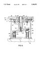
- FIG. 5 is an alternate embodiment of the engine housing section of the present invention for use with a second type of generator housing.
- FIG. 6 is a side view of a vertical shaft engine-pump assembly according to the present invention, shown in partial section.
- FIG. 1 is a side view, shown in partial section, of a vertical shaft engine-generator assembly according to the present invention.
- the engine housing may comprise a unitary housing, or it may have an upper section and one or more lower housing sections.
- engine 10 has a vertically-disposed crankshaft 12 (shown in phantom) that extends through an aperture 14 in a lower engine housing section 16.
- Crankshaft 12 has a centerline 12b that is coincident with the centerline of aperture 14.
- Housing section 16 includes the oil reservoir or sump for the engine.
- Housing section 16 has a first side 18 (FIGS. 3 through 5) and an opposite second side 20 (FIGS. 3 through 5).
- Lower engine housing section 16 also includes a threaded oil drain boss 21 having an oil drain plug 23.
- second side 20 Extending from second side 20 are a plurality of raised mounting bosses 22 and an engine pilot ring 24.
- the mounting bosses and the pilot ring are best shown in FIGS. 4 and 5.
- a projection 26 Also extending from second side 20 is a projection 26, which is opposite to a well or recess 28 in first side 18 of engine housing section 20.
- Well 28 and projection 26 are best shown in FIGS. 3 through 5.
- Some lower engine housing sections will not have a well 28 or a projection 26.
- the engine housing according to the present invention may be mounted to a standard generator housing, without modifying the generator housing.
- a customized generator housing is required.
- a key feature of the present invention is that the generator shaft is directly mounted to the engine crankshaft, and the generator housing is directly mounted to the engine housing, without modification to the generator assembly.
- engine crankshaft 12 is directly connected to generator shaft 30 at a crankshaft tapered end 12a.
- generator shaft 30 may be connected to crankshaft end 12a, including the use of tapers, keyways, and threaded connections.
- Generator 29 includes an upper generator housing 32 that is directly mounted to engine housing section 16. Extending from generator housing section 32 is a generator pilot ring 34 which, together with engine pilot 24, helps ensure concentricity between engine crankshaft 12 and generator stator 40. There are a number of other ways to ensure concentricity between crankshaft 12 and stator 40, such as including cast or machined features on lower engine housing section 16.
- Generator 29 also includes a plurality of throughbolts 34 that keep the generator housing together.
- Generator 29 also includes a rotor 36 affixed to shaft 30.
- a plurality of fan blades 38 extend from shaft 30.
- Disposed about rotor 36 and shaft 30 is a stator 40, as is well known in the art.
- FIG. 2 is a bottom view of engine housing 16 that more clearly depicts several features of the present invention.
- mounting bosses 16 are arranged about centerline 12b of crankshaft 12 in a pattern that corresponds to a SAE Recommended Practice, entitled “Mounting Flanges and Power Take-Off Shafts for Small Engines-SAE J609a” last revised July, 1965, Chapter 26, pages 26 through 27, FIG. 1, and incorporated by reference herein.
- Mounting bosses 22 have this arrangement, so that a generator, pump, or other device may be mounted to the vertical-shaft engine without modification of the device or device housing.
- the mounting bosses are disposed 90° from each other, so that angle a in FIG. 2 equals 90°.
- each of mounting bosses 22 is disposed at a radius r of 1 13/16 inches from centerline 12b, or 1.8125 inches.
- r of 1 13/16 inches from centerline 12b, or 1.8125 inches.
- other arrangements of the mounting bosses could be used, as long as the arrangement complies with a commonly-accepted practice, so that the device housing need not be modified for direct connection to the engine housing.
- engine housing section 16 includes a plurality of additional mounting bosses 42 that are used to mount the engine to a frame structure for stability. As also shown in FIG. 2, bolts 44 mount lower engine section 16 to an upper engine section.
- FIGS. 3 through 5 depict another important feature of the present invention.
- the vertical crankshaft engine depicted in FIGS. 3 through 5 has an oil slinger disposed in well 28 (FIG. 3) that slings the oil in the sump (engine housing section 16) to lubricate the moving components of the engine.
- Well 28 has a corresponding projection 26 that projects a height H from second side 20 of engine housing section 16.
- the present invention includes a plurality of raised mounting bosses 22 that extend from second side 20 by a length L, with length L being greater than or equal to height H. Length L is preferably between 0.0625 to 0.500 inches. In this way, projection 26 does not contact generator mounting section 32, so that the engine and the generator may be properly aligned with each other.
- a mounting bolt 46 is disposed in each of mounting bosses 22.
- FIGS. 4 and 5 depict other features of the present invention that are used to maintain the concentricity between engine crankshaft 12 and generator stator 40.
- FIGS. 4 and 5 are alternate embodiments of the lower engine housing section that are used with different types of standard generators. The embodiment depicted in FIG. 4 corresponds to the embodiment depicted in FIGS. 1 and 2.
- crankshaft 12 is kept in alignment by a crankshaft bearing 48 disposed within engine housing 16 and formed integral with housing 16.
- Engine pilot 24 extends from bearing 48 and is spaced from crankshaft 12.
- Engine pilot 24 defines an oil recess groove 50 in which an oil seal 52 is disposed.
- Oil seal 52 may be of the single-lipped or the double-lipped type.
- the type of generator housing depicted in FIG. 4 includes a raised generator pilot 54 that engages a raised portion of engine pilot 24.
- a substantially cylindrical adapter ring 56 is disposed radially inward from engine pilot 24 in oil recess groove 50, as well as radially inward from generator pilot 54.
- Adapter ring 56 may be spaced from crankshaft 12, as best shown in FIG. 2.
- FIG. 5 The embodiment depicted in FIG. 5 has a slightly different configuration due to the differences in the generator housing.
- a generator housing 32' has an extended generator pilot 54' that is substantially longer in the axial direction than generator pilot 54 in FIG. 4.
- engine housing section 16' has engine pilot 24' that is spaced further from crankshaft 12 when compared to engine pilot 24 in FIG. 4, so that generator pilot 54' is at least partially disposed within radially inward engine pilot 24'.
- Adapter ring 56 in FIG. 4 is unnecessary in the embodiment of FIG. 5 since extended generator pilot 54' has the same function as the adapter ring, namely to maintain the concentricity between crankshaft 12 and generator shaft 30 and the proper alignment of engine housing section 16' to generator housing section 32'.
- FIG. 6 is a side view, shown in partial section, of an engine-pump assembly incorporating the present invention.
- lower engine housing section 60 includes a first side 62 and an opposite second side 64.
- Lower engine housing 60 includes a threaded oil drain boss 61 that receives an oil drain plug 63.
- Extending from second side 64 are a plurality of raised mounting bosses 66, each having a length L.
- a projection 68 that has a height H.
- Projection 68 is opposed by a well (not shown) that holds an oil slinger, as discussed above in connection with FIGS. 1 through 4.
- Some engine housing sections do not have a projection 68. In the event that projection 68 is provided, it is desirable that length L be greater than or equal to height H to provide for proper alignment between the pump and the engine housing.
- an engine pilot 70 that at least partially surrounds an adapter ring 71 disposed in oil recess groove 72.
- An oil seal 73 is also disposed in groove 72.
- Pump housing 74 includes a pump pilot 75 extending therefrom. A portion of adapter ring 71 is disposed radially inward from pump pilot 75. Pump housing 74 is mounted to the low engine housing section via bolts 76, which in turn are received within mounting bosses 66.
- pump housing 74 includes an aperture 78 through which extends an engine crankshaft 80.
- a swash plate 82 receives extended crankshaft 80, and is bolted thereto via a bolt 84.
- swash plate 82 Affixed to swash plate 82 is a wear plate 86 that engages reciprocable pistons 88.
- a needle bearing 90 is disposed between wear plate 86 and swash plate 82.
- Return springs 92 return pistons 88 to their uppermost positions.
- Swash plate 82 is kept in registration with crankshaft 80 by a keyway 94.
- the engine-pump assembly operates in the following manner. As crankshaft 80 rotates, swash plate 82 and wear plate 86 rotate therewith. The wear plate engages pistons 88, thereby causing them to reciprocate in a manner that is well known in the art. As the pistons reciprocate, they compress water or another fluid in pump head 96 to pump the fluid.
- engine housing section 60 preferably includes 4 spaced mounting bosses 66 that are arranged in accordance with the SAE J609a Standard, such that the mounting bosses are disposed 90° from each other and each of the mounting bosses is disposed 1.8125 inches from centerline 80a of crankshaft 80.
- FIG. 6 depicts the invention incorporated into an engine-swash plate pump assembly, it will be apparent to those skilled in the art that the present invention may be incorporated into assemblies that include other types of pumps, or even other types of devices altogether, as long as the pump or other device does not need to be modified for connection to the vertical shaft engine housing.
Landscapes
- Engineering & Computer Science (AREA)
- Chemical & Material Sciences (AREA)
- Combustion & Propulsion (AREA)
- Mechanical Engineering (AREA)
- General Engineering & Computer Science (AREA)
- Cylinder Crankcases Of Internal Combustion Engines (AREA)
Abstract
Description
Claims (16)
Priority Applications (4)
| Application Number | Priority Date | Filing Date | Title |
|---|---|---|---|
| US08/497,298 US5546901A (en) | 1995-06-30 | 1995-06-30 | Engine housing for an engine-device assembly |
| EP96913269A EP0835369A1 (en) | 1995-06-30 | 1996-04-30 | Engine housing for an engine-device assembly |
| AU56334/96A AU5633496A (en) | 1995-06-30 | 1996-04-30 | Engine housing for an engine-device assembly |
| PCT/US1996/005981 WO1997002415A1 (en) | 1995-06-30 | 1996-04-30 | Engine housing for an engine-device assembly |
Applications Claiming Priority (1)
| Application Number | Priority Date | Filing Date | Title |
|---|---|---|---|
| US08/497,298 US5546901A (en) | 1995-06-30 | 1995-06-30 | Engine housing for an engine-device assembly |
Publications (1)
| Publication Number | Publication Date |
|---|---|
| US5546901A true US5546901A (en) | 1996-08-20 |
Family
ID=23976282
Family Applications (1)
| Application Number | Title | Priority Date | Filing Date |
|---|---|---|---|
| US08/497,298 Expired - Lifetime US5546901A (en) | 1995-06-30 | 1995-06-30 | Engine housing for an engine-device assembly |
Country Status (4)
| Country | Link |
|---|---|
| US (1) | US5546901A (en) |
| EP (1) | EP0835369A1 (en) |
| AU (1) | AU5633496A (en) |
| WO (1) | WO1997002415A1 (en) |
Cited By (34)
| Publication number | Priority date | Publication date | Assignee | Title |
|---|---|---|---|---|
| WO1998025049A1 (en) * | 1996-12-03 | 1998-06-11 | Generac Corporation | Engine-generator set with integral gear reduction |
| US5823752A (en) * | 1997-02-28 | 1998-10-20 | Generac Portable Products, Llc | Adapter for mechanically coupling a pump and a prime mover |
| US5965999A (en) * | 1997-03-20 | 1999-10-12 | Coleman Powermate, Inc. | Vertical generator assembly |
| USD418809S (en) * | 1998-08-13 | 2000-01-11 | Coleman Powermate, Inc. | Generator system |
| WO2000010241A1 (en) * | 1998-08-13 | 2000-02-24 | Coleman Powermate, Inc. | Generator system with vertically shafted engine |
| GB2360878A (en) * | 2000-02-08 | 2001-10-03 | Honda Motor Co Ltd | Structure for fitting alternative generator stators to an engine |
| US20020149203A1 (en) * | 2001-04-13 | 2002-10-17 | Fuji Jukogyo Kabushiki Kaisha | Engine generator |
| US20030037755A1 (en) * | 2001-08-22 | 2003-02-27 | Akifumi Nomura | Crankshaft phase adjustment structure |
| US6568355B2 (en) * | 2000-04-14 | 2003-05-27 | Fuji Jukogyo Kabushiki Kaisha | Engine generator |
| US6624543B1 (en) * | 1999-09-23 | 2003-09-23 | Illinois Tool Works Inc. | Method and apparatus for centering a generator stator and rotor |
| US20040191091A1 (en) * | 2003-03-28 | 2004-09-30 | Kevin Steffes | Engine and pump assembly having combined housing |
| US6952056B2 (en) | 2003-08-06 | 2005-10-04 | Briggs & Stratton Power Products Group, Llc | Generator including vertically shafted engine |
| EP1247055A4 (en) * | 2000-01-10 | 2006-03-15 | Us Environment | HYDRAULIC HYBRID VEHICLE |
| US20060258237A1 (en) * | 2005-05-13 | 2006-11-16 | Sodemann Wesley C | Standby generator |
| US20080184702A1 (en) * | 2007-02-02 | 2008-08-07 | Gen-Tran Corporation | Exhaust system for enclosures for engine-powered equipment |
| US8056333B1 (en) | 2007-08-01 | 2011-11-15 | Hydro-Gear Limited Partnership | Pump and engine configuration |
| US8334604B1 (en) * | 2010-09-30 | 2012-12-18 | The United States Of America As Represented By The Secretary Of The Navy | Integrated external combustion cam engine-generator |
| US8496079B2 (en) | 2009-09-16 | 2013-07-30 | Swissauto Powersport Llc | Electric vehicle and on-board battery charging apparatus therefore |
| US8925311B1 (en) | 2009-07-24 | 2015-01-06 | Hydro-Gear Limited Partnership | Transmission and engine configuration |
| US9187083B2 (en) | 2009-09-16 | 2015-11-17 | Polaris Industries Inc. | System and method for charging an on-board battery of an electric vehicle |
| US9470269B2 (en) | 2013-08-22 | 2016-10-18 | Stanley Black & Decker, Inc. | Hydraulic power unit |
| CN107420191A (en) * | 2016-03-15 | 2017-12-01 | 斯太尔动力有限责任公司 | Generating equipment for Mobile solution |
| US20180331597A1 (en) * | 2017-05-15 | 2018-11-15 | Briggs & Stratton Corporation | Electric powerhead |
| US10744868B2 (en) | 2016-06-14 | 2020-08-18 | Polaris Industries Inc. | Hybrid utility vehicle |
| US10780770B2 (en) | 2018-10-05 | 2020-09-22 | Polaris Industries Inc. | Hybrid utility vehicle |
| US11370266B2 (en) | 2019-05-16 | 2022-06-28 | Polaris Industries Inc. | Hybrid utility vehicle |
| US12122228B2 (en) | 2014-12-19 | 2024-10-22 | Polaris Industries Inc. | Utility vehicle |
| US12172518B2 (en) | 2019-04-30 | 2024-12-24 | Polaris Industries Inc. | Vehicle |
| US12187127B2 (en) | 2020-05-15 | 2025-01-07 | Polaris Industries Inc. | Off-road vehicle |
| US12214654B2 (en) | 2021-05-05 | 2025-02-04 | Polaris Industries Inc. | Exhaust assembly for a utility vehicle |
| US12385429B2 (en) | 2022-06-13 | 2025-08-12 | Polaris Industries Inc. | Powertrain for a utility vehicle |
| US12384464B2 (en) | 2020-05-15 | 2025-08-12 | Polaris Industries Inc. | Off-road vehicle |
| US12485981B2 (en) | 2021-03-24 | 2025-12-02 | Polaris Industries Inc. | Electric recreational vehicle |
| US12552246B2 (en) | 2015-05-15 | 2026-02-17 | Polaris Industries Inc. | Utility vehicle |
Families Citing this family (1)
| Publication number | Priority date | Publication date | Assignee | Title |
|---|---|---|---|---|
| CN217769776U (en) | 2019-11-08 | 2022-11-08 | 米沃奇电动工具公司 | Battery-powered independent motor unit |
Citations (12)
| Publication number | Priority date | Publication date | Assignee | Title |
|---|---|---|---|---|
| US1701340A (en) * | 1929-02-05 | Intern ax-combustion engine and generator | ||
| US3046899A (en) * | 1959-08-14 | 1962-07-31 | Rockwell Gmbh | Generator or pump assembly |
| US4203710A (en) * | 1976-10-20 | 1980-05-20 | Tecumseh Products Company | Unified pump and generator arrangement |
| US4622923A (en) * | 1984-07-31 | 1986-11-18 | Yanmar Diesel Engine Co., Ltd. | Encased engine generator |
| US4676065A (en) * | 1985-03-04 | 1987-06-30 | Hale Fire Pump Company | Portable engine-pump assembly |
| US4677940A (en) * | 1985-08-09 | 1987-07-07 | Kohler Co. | Cooling system for a compact generator |
| US4698975A (en) * | 1984-07-16 | 1987-10-13 | Honda Giken Kogyo Kabushiki Kaisha | Engine-operated machine |
| US4779905A (en) * | 1986-08-25 | 1988-10-25 | Kubato Ltd. | Forcedly air-cooled engine generator of vertical shaft type |
| US4859886A (en) * | 1986-02-28 | 1989-08-22 | Honda Giken Kogyo Kabushiki Kaisha | Portable engine-operated electric generator |
| US5031591A (en) * | 1989-01-30 | 1991-07-16 | Honda Giken Kogyo Kabushiki Kaisha | OHC vertical crankshaft engine |
| US5376877A (en) * | 1992-06-11 | 1994-12-27 | Generac Corporation | Engine-driven generator |
| US5458100A (en) * | 1994-11-10 | 1995-10-17 | Kohler Co. | Pilot ring attachment assembly |
Family Cites Families (2)
| Publication number | Priority date | Publication date | Assignee | Title |
|---|---|---|---|---|
| JPS6032331Y2 (en) * | 1981-06-05 | 1985-09-27 | 株式会社クボタ | Impeller type lubrication system for vertical engine |
| DE4304630A1 (en) * | 1993-02-16 | 1994-08-18 | Prettl Rolf | Generators for uses such as camping, gardening or boats |
-
1995
- 1995-06-30 US US08/497,298 patent/US5546901A/en not_active Expired - Lifetime
-
1996
- 1996-04-30 AU AU56334/96A patent/AU5633496A/en not_active Abandoned
- 1996-04-30 WO PCT/US1996/005981 patent/WO1997002415A1/en not_active Ceased
- 1996-04-30 EP EP96913269A patent/EP0835369A1/en not_active Withdrawn
Patent Citations (12)
| Publication number | Priority date | Publication date | Assignee | Title |
|---|---|---|---|---|
| US1701340A (en) * | 1929-02-05 | Intern ax-combustion engine and generator | ||
| US3046899A (en) * | 1959-08-14 | 1962-07-31 | Rockwell Gmbh | Generator or pump assembly |
| US4203710A (en) * | 1976-10-20 | 1980-05-20 | Tecumseh Products Company | Unified pump and generator arrangement |
| US4698975A (en) * | 1984-07-16 | 1987-10-13 | Honda Giken Kogyo Kabushiki Kaisha | Engine-operated machine |
| US4622923A (en) * | 1984-07-31 | 1986-11-18 | Yanmar Diesel Engine Co., Ltd. | Encased engine generator |
| US4676065A (en) * | 1985-03-04 | 1987-06-30 | Hale Fire Pump Company | Portable engine-pump assembly |
| US4677940A (en) * | 1985-08-09 | 1987-07-07 | Kohler Co. | Cooling system for a compact generator |
| US4859886A (en) * | 1986-02-28 | 1989-08-22 | Honda Giken Kogyo Kabushiki Kaisha | Portable engine-operated electric generator |
| US4779905A (en) * | 1986-08-25 | 1988-10-25 | Kubato Ltd. | Forcedly air-cooled engine generator of vertical shaft type |
| US5031591A (en) * | 1989-01-30 | 1991-07-16 | Honda Giken Kogyo Kabushiki Kaisha | OHC vertical crankshaft engine |
| US5376877A (en) * | 1992-06-11 | 1994-12-27 | Generac Corporation | Engine-driven generator |
| US5458100A (en) * | 1994-11-10 | 1995-10-17 | Kohler Co. | Pilot ring attachment assembly |
Cited By (57)
| Publication number | Priority date | Publication date | Assignee | Title |
|---|---|---|---|---|
| WO1998025049A1 (en) * | 1996-12-03 | 1998-06-11 | Generac Corporation | Engine-generator set with integral gear reduction |
| US5816102A (en) * | 1996-12-03 | 1998-10-06 | Generac Corporation | Engine-generator set with integral gear reduction |
| US5823752A (en) * | 1997-02-28 | 1998-10-20 | Generac Portable Products, Llc | Adapter for mechanically coupling a pump and a prime mover |
| US5965999A (en) * | 1997-03-20 | 1999-10-12 | Coleman Powermate, Inc. | Vertical generator assembly |
| US6310404B1 (en) | 1998-08-13 | 2001-10-30 | Coleman Powermate, Inc. | Generator system with vertically shafted engine |
| WO2000010241A1 (en) * | 1998-08-13 | 2000-02-24 | Coleman Powermate, Inc. | Generator system with vertically shafted engine |
| US6084313A (en) * | 1998-08-13 | 2000-07-04 | Coleman Powermate, Inc. | Generator system with vertically shafted engine |
| US6181019B1 (en) | 1998-08-13 | 2001-01-30 | Coleman Powermate, Inc. | Generator system with vertically shafted engine |
| US6313543B1 (en) * | 1998-08-13 | 2001-11-06 | Coleman Powermate, Inc. | Generator system with vertically shafted engine |
| USD418809S (en) * | 1998-08-13 | 2000-01-11 | Coleman Powermate, Inc. | Generator system |
| US6624543B1 (en) * | 1999-09-23 | 2003-09-23 | Illinois Tool Works Inc. | Method and apparatus for centering a generator stator and rotor |
| EP1247055A4 (en) * | 2000-01-10 | 2006-03-15 | Us Environment | HYDRAULIC HYBRID VEHICLE |
| GB2360878B (en) * | 2000-02-08 | 2004-12-29 | Honda Motor Co Ltd | Structure for fitting generator stator to engine |
| GB2360878A (en) * | 2000-02-08 | 2001-10-03 | Honda Motor Co Ltd | Structure for fitting alternative generator stators to an engine |
| US6570281B2 (en) | 2000-02-08 | 2003-05-27 | Honda Giken Kogyo Kabushiki Kaisha | Structure for fitting generator stator to engine |
| US6568355B2 (en) * | 2000-04-14 | 2003-05-27 | Fuji Jukogyo Kabushiki Kaisha | Engine generator |
| US20020149203A1 (en) * | 2001-04-13 | 2002-10-17 | Fuji Jukogyo Kabushiki Kaisha | Engine generator |
| US6825573B2 (en) * | 2001-04-13 | 2004-11-30 | Fuji Jukogyo Kabushiki Kaisha | Engine generator |
| EP1249590A3 (en) * | 2001-04-13 | 2003-07-02 | Fuji Jukogyo Kabushiki Kaisha | Engine generator |
| US20030037755A1 (en) * | 2001-08-22 | 2003-02-27 | Akifumi Nomura | Crankshaft phase adjustment structure |
| US6698393B2 (en) * | 2001-08-22 | 2004-03-02 | Honda Giken Kogyo Kabushiki Kaisha | Crankshaft phase adjustment structure |
| US20040191091A1 (en) * | 2003-03-28 | 2004-09-30 | Kevin Steffes | Engine and pump assembly having combined housing |
| US6886523B2 (en) * | 2003-03-28 | 2005-05-03 | Tecumseh Products Company | Engine and pump assembly having combined housing |
| US6952056B2 (en) | 2003-08-06 | 2005-10-04 | Briggs & Stratton Power Products Group, Llc | Generator including vertically shafted engine |
| US20050264014A1 (en) * | 2003-08-06 | 2005-12-01 | Briggs & Stratton Corp. | Generator including vertically shafted engine |
| US6998725B2 (en) | 2003-08-06 | 2006-02-14 | Briggs & Stratton Power Products Group, Llc | Generator including vertically shafted engine |
| US20060258237A1 (en) * | 2005-05-13 | 2006-11-16 | Sodemann Wesley C | Standby generator |
| US7314397B2 (en) | 2005-05-13 | 2008-01-01 | Briggs & Stratton Corporation | Standby generator |
| US20080184702A1 (en) * | 2007-02-02 | 2008-08-07 | Gen-Tran Corporation | Exhaust system for enclosures for engine-powered equipment |
| US8733091B1 (en) | 2007-08-01 | 2014-05-27 | Hydro-Gear Limited Partnership | Pump and engine configuration |
| US8056333B1 (en) | 2007-08-01 | 2011-11-15 | Hydro-Gear Limited Partnership | Pump and engine configuration |
| US8468819B1 (en) | 2007-08-01 | 2013-06-25 | Hydro-Gear Limited Partnership | Pump and engine configuration |
| US9394892B1 (en) | 2007-08-01 | 2016-07-19 | Hydro-Gear Limited Partnership | Pump assembly and support |
| US10364874B1 (en) | 2009-07-24 | 2019-07-30 | Hydro-Gear Limited Partnership | Transmission and engine configuration |
| US8925311B1 (en) | 2009-07-24 | 2015-01-06 | Hydro-Gear Limited Partnership | Transmission and engine configuration |
| US9726269B1 (en) | 2009-07-24 | 2017-08-08 | Hydro-Gear Limited Partnership | Transmission and engine configuration |
| US9187083B2 (en) | 2009-09-16 | 2015-11-17 | Polaris Industries Inc. | System and method for charging an on-board battery of an electric vehicle |
| US8496079B2 (en) | 2009-09-16 | 2013-07-30 | Swissauto Powersport Llc | Electric vehicle and on-board battery charging apparatus therefore |
| US8334604B1 (en) * | 2010-09-30 | 2012-12-18 | The United States Of America As Represented By The Secretary Of The Navy | Integrated external combustion cam engine-generator |
| US9470269B2 (en) | 2013-08-22 | 2016-10-18 | Stanley Black & Decker, Inc. | Hydraulic power unit |
| US12122228B2 (en) | 2014-12-19 | 2024-10-22 | Polaris Industries Inc. | Utility vehicle |
| US12552246B2 (en) | 2015-05-15 | 2026-02-17 | Polaris Industries Inc. | Utility vehicle |
| CN107420191A (en) * | 2016-03-15 | 2017-12-01 | 斯太尔动力有限责任公司 | Generating equipment for Mobile solution |
| US10744868B2 (en) | 2016-06-14 | 2020-08-18 | Polaris Industries Inc. | Hybrid utility vehicle |
| US20180331597A1 (en) * | 2017-05-15 | 2018-11-15 | Briggs & Stratton Corporation | Electric powerhead |
| US10780770B2 (en) | 2018-10-05 | 2020-09-22 | Polaris Industries Inc. | Hybrid utility vehicle |
| US12420624B2 (en) | 2018-10-05 | 2025-09-23 | Polaris Industries, Inc. | Hybrid utility vehicle |
| US12172518B2 (en) | 2019-04-30 | 2024-12-24 | Polaris Industries Inc. | Vehicle |
| US12194808B2 (en) | 2019-05-16 | 2025-01-14 | Polaris Industries Inc. | Hybrid utility vehicle |
| US12311728B2 (en) | 2019-05-16 | 2025-05-27 | Polaris Industries Inc. | Hybrid utility vehicle |
| US11370266B2 (en) | 2019-05-16 | 2022-06-28 | Polaris Industries Inc. | Hybrid utility vehicle |
| US12187127B2 (en) | 2020-05-15 | 2025-01-07 | Polaris Industries Inc. | Off-road vehicle |
| US12337690B2 (en) | 2020-05-15 | 2025-06-24 | Polaris Industries Inc. | Off-road vehicle |
| US12384464B2 (en) | 2020-05-15 | 2025-08-12 | Polaris Industries Inc. | Off-road vehicle |
| US12485981B2 (en) | 2021-03-24 | 2025-12-02 | Polaris Industries Inc. | Electric recreational vehicle |
| US12214654B2 (en) | 2021-05-05 | 2025-02-04 | Polaris Industries Inc. | Exhaust assembly for a utility vehicle |
| US12385429B2 (en) | 2022-06-13 | 2025-08-12 | Polaris Industries Inc. | Powertrain for a utility vehicle |
Also Published As
| Publication number | Publication date |
|---|---|
| WO1997002415A1 (en) | 1997-01-23 |
| AU5633496A (en) | 1997-02-05 |
| EP0835369A1 (en) | 1998-04-15 |
Similar Documents
| Publication | Publication Date | Title |
|---|---|---|
| US5546901A (en) | Engine housing for an engine-device assembly | |
| US3552886A (en) | Compressor unit with self-contained drive means | |
| EP0780573A2 (en) | High pressure water pump system | |
| US5876188A (en) | Oil pump arrangement for four-cycle outboard motor | |
| US5653584A (en) | Motor/pump mounting arrangement for a vertically mounting high pressure water pump | |
| EP0386320A1 (en) | Suction line connector for hermetic compressor | |
| JP3380548B2 (en) | Hydraulic pump for vehicle engine | |
| CA1322741C (en) | Hermetic compressor having resilient internal mounting | |
| US5332368A (en) | Air compressor having a high pressure output | |
| JPS6029604Y2 (en) | Internal combustion engine lubricating oil pump | |
| US5848959A (en) | Lubicated vertical transmission shaft for driving a centrifugal drum | |
| KR940010465B1 (en) | Low noise pump assembly | |
| US6056515A (en) | Hydrocleaning machine with pump mounting closure lid | |
| US4664228A (en) | Lubrication system for a vertical shaft engine | |
| CA1172220A (en) | Oil pump for hermetic compressor | |
| US4944265A (en) | Oil restricting head gasket construction | |
| US6481981B1 (en) | Motor-driven assembly | |
| US6886523B2 (en) | Engine and pump assembly having combined housing | |
| US7866956B2 (en) | Oil pump for motorcycle | |
| GB2023719A (en) | Radial piston pump | |
| US5108271A (en) | Multiple connection for rotation vacuum pumps | |
| US3583833A (en) | Motor driven pump | |
| US11261876B2 (en) | Fan with integrated shaft guard | |
| US4384555A (en) | Cap for larger end portion of connecting rod of two-stroke internal combustion engine | |
| US4650398A (en) | Bearing unit with integrated pump |
Legal Events
| Date | Code | Title | Description |
|---|---|---|---|
| AS | Assignment |
Owner name: BRIGGS & STRATTON CORPORATION, WISCONSIN Free format text: ASSIGNMENT OF ASSIGNORS INTEREST;ASSIGNORS:ACKER, RICHARD M.;BRUNELLI, BRIAN T.;KAUTZER, DOUGLAS H.;REEL/FRAME:007631/0730 Effective date: 19950626 |
|
| STCF | Information on status: patent grant |
Free format text: PATENTED CASE |
|
| FPAY | Fee payment |
Year of fee payment: 4 |
|
| FEPP | Fee payment procedure |
Free format text: PAYOR NUMBER ASSIGNED (ORIGINAL EVENT CODE: ASPN); ENTITY STATUS OF PATENT OWNER: LARGE ENTITY |
|
| FPAY | Fee payment |
Year of fee payment: 8 |
|
| FPAY | Fee payment |
Year of fee payment: 12 |
|
| FEPP | Fee payment procedure |
Free format text: PAYER NUMBER DE-ASSIGNED (ORIGINAL EVENT CODE: RMPN); ENTITY STATUS OF PATENT OWNER: LARGE ENTITY Free format text: PAYOR NUMBER ASSIGNED (ORIGINAL EVENT CODE: ASPN); ENTITY STATUS OF PATENT OWNER: LARGE ENTITY |