US5546175A - Image fixing device and method thereof - Google Patents
Image fixing device and method thereof Download PDFInfo
- Publication number
- US5546175A US5546175A US08/528,012 US52801295A US5546175A US 5546175 A US5546175 A US 5546175A US 52801295 A US52801295 A US 52801295A US 5546175 A US5546175 A US 5546175A
- Authority
- US
- United States
- Prior art keywords
- heat roller
- roller
- pressure
- image fixing
- area
- Prior art date
- Legal status (The legal status is an assumption and is not a legal conclusion. Google has not performed a legal analysis and makes no representation as to the accuracy of the status listed.)
- Expired - Fee Related
Links
- 238000000034 method Methods 0.000 title claims description 31
- 230000002093 peripheral effect Effects 0.000 claims abstract description 35
- 238000012546 transfer Methods 0.000 claims abstract description 19
- 239000013013 elastic material Substances 0.000 claims abstract description 12
- 238000010438 heat treatment Methods 0.000 claims abstract description 5
- 238000003825 pressing Methods 0.000 claims abstract description 4
- 239000000463 material Substances 0.000 claims description 12
- 239000010410 layer Substances 0.000 description 74
- 238000002474 experimental method Methods 0.000 description 20
- 239000000853 adhesive Substances 0.000 description 15
- 230000001070 adhesive effect Effects 0.000 description 15
- XAGFODPZIPBFFR-UHFFFAOYSA-N aluminium Chemical compound [Al] XAGFODPZIPBFFR-UHFFFAOYSA-N 0.000 description 11
- 230000008569 process Effects 0.000 description 11
- 229910052782 aluminium Inorganic materials 0.000 description 10
- 229920001296 polysiloxane Polymers 0.000 description 10
- 239000003795 chemical substances by application Substances 0.000 description 9
- 229920001971 elastomer Polymers 0.000 description 9
- 238000007788 roughening Methods 0.000 description 8
- 230000003746 surface roughness Effects 0.000 description 7
- 239000011248 coating agent Substances 0.000 description 5
- 238000000576 coating method Methods 0.000 description 5
- 238000005452 bending Methods 0.000 description 4
- 238000010276 construction Methods 0.000 description 4
- 230000000694 effects Effects 0.000 description 4
- 238000004519 manufacturing process Methods 0.000 description 4
- 229910052751 metal Inorganic materials 0.000 description 4
- 239000002184 metal Substances 0.000 description 4
- 229920002379 silicone rubber Polymers 0.000 description 4
- 239000004945 silicone rubber Substances 0.000 description 4
- 229910000831 Steel Inorganic materials 0.000 description 3
- 230000006866 deterioration Effects 0.000 description 3
- 238000005498 polishing Methods 0.000 description 3
- 230000009467 reduction Effects 0.000 description 3
- 238000005488 sandblasting Methods 0.000 description 3
- 229920002545 silicone oil Polymers 0.000 description 3
- 239000010959 steel Substances 0.000 description 3
- XEEYBQQBJWHFJM-UHFFFAOYSA-N Iron Chemical compound [Fe] XEEYBQQBJWHFJM-UHFFFAOYSA-N 0.000 description 2
- 229920001774 Perfluoroether Polymers 0.000 description 2
- 230000015572 biosynthetic process Effects 0.000 description 2
- 238000005520 cutting process Methods 0.000 description 2
- 230000003247 decreasing effect Effects 0.000 description 2
- -1 fluororesin Substances 0.000 description 2
- 238000012986 modification Methods 0.000 description 2
- 230000004048 modification Effects 0.000 description 2
- 229910000838 Al alloy Inorganic materials 0.000 description 1
- RYGMFSIKBFXOCR-UHFFFAOYSA-N Copper Chemical compound [Cu] RYGMFSIKBFXOCR-UHFFFAOYSA-N 0.000 description 1
- 229910000881 Cu alloy Inorganic materials 0.000 description 1
- 235000010724 Wisteria floribunda Nutrition 0.000 description 1
- 239000002775 capsule Substances 0.000 description 1
- 239000010949 copper Substances 0.000 description 1
- 229910052802 copper Inorganic materials 0.000 description 1
- 230000008878 coupling Effects 0.000 description 1
- 238000010168 coupling process Methods 0.000 description 1
- 238000005859 coupling reaction Methods 0.000 description 1
- 230000003467 diminishing effect Effects 0.000 description 1
- 238000009503 electrostatic coating Methods 0.000 description 1
- 239000004744 fabric Substances 0.000 description 1
- 238000010304 firing Methods 0.000 description 1
- 229920001973 fluoroelastomer Polymers 0.000 description 1
- 229910052742 iron Inorganic materials 0.000 description 1
- 238000005259 measurement Methods 0.000 description 1
- 239000000155 melt Substances 0.000 description 1
- 239000000203 mixture Substances 0.000 description 1
- 239000004033 plastic Substances 0.000 description 1
- 239000000843 powder Substances 0.000 description 1
- 238000007639 printing Methods 0.000 description 1
- 230000000452 restraining effect Effects 0.000 description 1
- 229920002050 silicone resin Polymers 0.000 description 1
- 239000002904 solvent Substances 0.000 description 1
- 239000002344 surface layer Substances 0.000 description 1
Images


Classifications
-
- G—PHYSICS
- G03—PHOTOGRAPHY; CINEMATOGRAPHY; ANALOGOUS TECHNIQUES USING WAVES OTHER THAN OPTICAL WAVES; ELECTROGRAPHY; HOLOGRAPHY
- G03G—ELECTROGRAPHY; ELECTROPHOTOGRAPHY; MAGNETOGRAPHY
- G03G15/00—Apparatus for electrographic processes using a charge pattern
- G03G15/20—Apparatus for electrographic processes using a charge pattern for fixing, e.g. by using heat
- G03G15/2003—Apparatus for electrographic processes using a charge pattern for fixing, e.g. by using heat using heat
- G03G15/2014—Apparatus for electrographic processes using a charge pattern for fixing, e.g. by using heat using heat using contact heat
- G03G15/2064—Apparatus for electrographic processes using a charge pattern for fixing, e.g. by using heat using heat using contact heat combined with pressure
Definitions
- the present invention relates to an image fixing device and a method thereof used in a machine employing the electrophotographic method such as a copying machine, facsimile apparatus or printer.
- the releasing layer 5 is formed on purpose to prevent attachment of toner, which has transferred from the surface of the recording sheet, to the peripheral surface of the core 3 and is made of heat-resisting material such as fluororesin, silicone rubber or silicone resin.
- the core 3 is a cylinder made of material such as aluminum, aluminum alloy, copper or copper alloy, and the diameter of which is 20 mm to 40 mm, thickness is 0.5 mm to 3 mm.
- the core 3 is coated with fluororesin as a releasing layer 5 whose thickness is 20 ⁇ m to 100 ⁇ m.
- the pressure roller 2 is disposed to press-contact the heat roller 1 and apply pressure thereto, and comprises a core 6 and a releasing layer 7 made of heat-resisting rubber and coating the peripheral surface of the core 6 to improve paper stripping capability.
- heat-resisting rubber for example, silicone rubber or fluororubber can be used.
- the fixing device employing the heat roller method has a problem that wrinkling is apt to be generated on the recording sheet 9 when the sheet passes through a nip between the roller 1 and roller 2.
- a heat roller 1 with a gradient on its peripheral surface for example, a heat roller 1 with the diameter of the central portion smaller than that of the end portions by 30 ⁇ m to 200 ⁇ m, approximately (hereinafter referred to this heat roller as a reversed crown roller), has been conventionally used.
- Use of the reversed crown roller generates difference in carrying speed of the recording sheet in the direction of width of the recording sheet, whereby the recording sheet is pulled in the direction of both ends and generation of wrinkling can be prevented.
- the core 3 is plastically deformed by extruding a bar or pipe, and is cut in plural rollers having a predetermined length. Then the peripheral surface of the core 3 is formed in a shape of reversed crown by cutting work by lathing or by centerless polishing, and is coated with the releasing layer 5.
- accuracy is required in forming the core 3 in the shape of reversed crown so that the generation of wrinkling on the recording sheet 9 is prevented; therefore, the cost increases.
- inventors of the present invention has studied to prevent occurrence of wrinkling on the recording sheet 9 while using a roller having a uniform diameter over the longitudinal direction.
- the peripheral surface of the core 3 is finished to be almost a mirror surface. Therefore, despite the releasing layer 5 formed on the peripheral surface of the core 3, there is a fear that the releasing layer is debonded from the core 3 because the adhesive force between the core 3 and the releasing layer 5 is weakened though the life of the releasing layer still remains.
- the peripheral surface of the core 3 is roughened, for example, by sand blasting on purpose to increase the mechanical coupling force (anchor effect) by increase of area which contacts the releasing layer.
- the core 3 having uniform diameter over the longitudinal direction which is made by extruding alone may be used; therefore polishing for forming the core 3 into the shape of reversed crown is unnecessary.
- the surface of the core 3 after extruding is also like a mirror surface, the adhesive force between the core 3 and the releasing layer 5 should be improved by the surface roughening process which is complicated and expensive to prevent alebonding of the releasing layer 5 from the core 3 before expiration of life of the releasing layer 5.
- a stripper finger has been conventionally used for stripping the recording sheet 9 from the heat roller 1 compulsorily.
- Such stripper finger always scratches the releasing layer 5 with its sharp point, whereby generation of the scratches or cracks and wear of the releasing layer 5 is accelerated, and accordingly the deterioration of the releasing layer 5 is induced. This wear or deterioration has been the cause of debonding of the releasing layer 5 from the core 3.
- the present invention has been made in view of the above circumstances and has as an object of provision of an image fixing device capable of preventing occurrence of wrinkling in a recording sheet while a heat roller with a uniform outer diameter over the longitudinal direction is used.
- Another object of the present invention is to provide an image fixing method, in the case where a heat roller comprising a core having a uniform outer diameter and a releasing layer is used as the heat roller having uniform outer diameter, which prevents debonding of the releasing layer from the core before expiration of life of the releasing layer without executing a surface roughening process on the core which is expensive and requires much labor.
- an image fixing device of the present invention comprises a heat roller which is a hollow cylindrical member rotatably supported at both end portions and having heating means inside thereof, pressure means press-contacted to the heat roller for pressing the transfer member passing between the heat roller and the pressure means against to a peripheral surface of the heat roller, and the pressure means is a pressure roller disposed approximately parallel to the heat roller and supported rotatably, at least one of the heat roller and the pressure roller has a layer of elastic material on its peripheral surface, and a value A/B is set to be within a range from 0.7 to 0.8 wherein A represents a nip width at an approximate central portion of an area between the heat roller and the pressure roller where the transfer member passes through and B represents a nip width at end portions of the area.
- FIG. 1 is a sectional side elevation view showing a first embodiment of an image fixing device according to the present invention
- FIG. 3 shows a relation among the flexural rigidity of the heat roller, the press-contact force and a nip area shape index C and a relation between the nip area shape index C and the rate of occurrence of wrinkling in the case where the heat roller of 15 mm outer diameter is used;
- FIG. 4 shows a relation among the flexural rigidity of the heat roller, the press-contact force and the nip area shape index C and a relation between the nip area shape index C and the rate of occurrence of wrinkling in the case where the heat roller of 20 mm outer diameter is used;
- FIG. 5 shows a relation among the flexural rigidity of the heat roller, the press-contact force and the nip area shape index C and a relation between the nip area shape index C and the rate of occurrence of wrinkling in the case where the heat roller of 25 mm outer diameter is used;
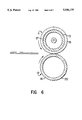
- FIG. 6 is a schematic construction view showing a variation of the image fixing device shown in FIG. 1;
- FIGS. 7(a)-7(b) and 7(c) are schematic construction views showing a second embodiment of the image fixing device according to the present invention and a view showing a shape of the nip area formed between the heat roller and the pressure applying means in the second embodiment, respectively.
- the inventors of the present invention has made experiments on occurrence of wrinkling in a recording sheet using a heat roller with a uniform outer diameter over the longitudinal direction (hereinafter, referred to as a roller having uniform outer diameter).
- shape of a contact area hereinafter referred to as a nip area
- the shape of the nip area can be represented by a nip area shape index C as follows:
- A is the width of the nip area (a spacing between the heat roller 1 and pressure applying means 2) at the central portion
- B is the width of the nip area at both ends of the widest recording sheet which passes the nip area as shown in FIG. 2.
- the nip area shape index C for a roller with a uniform outer diameter is determined based on the length of the heat roller, the load between the heat roller and pressure applying means, and rigidity of the heat roller and the pressure applying means. That is, even in the case of the roller having the same length and rigidity, the nip area shape index C becomes smaller as the load increases. If the length of the roller is fixed and the same load is applied, the nip area shape index C becomes larger as the rigidity of the roller increases. Even if the load and the rigidity of the roller are fixed, the degree of bending of the roller becomes higher as the length of the roller increases, thus decreasing the nip area shape index C.
- the nip area shape index C is approximately in proportion to EI/W (the roller rigidity) on condition that the length of the roller is fixed, wherein W is the load, E is Young's modulus of material of the core of the roller, I is the second moment of area of the roller and EI represents flexural rigidity of the roller.
- nip area shape index C exceeds 0.8, effect of restraining of wrinkling occurrence according to difference between the recording sheet carrying speed at the central portion of the roller and that at the end portions of the roller. If the nip area shape index C is less than 0.7, phenomenon of increasing of wrinkling occurrence caused by the nip pressure is larger than the effect of reduction of wrinkling occurrence according to the difference in the recording sheet carrying speed.
- the use of the oilless toner in forming a toner image resolves the fear that the toner fuses to the heat roller; accordingly, use of the conventional releasing agent is unnecessary, and moreover, the conventional stripper finger also becomes unnecessary because it is easy to strip the recording sheet from the heat roller. Consequently, deterioration of the releasing layer can be prevented, and furthermore the releasing layer is hard to be debonded from the core.
- a heat roller 1 used here is made by coating the surface of a core 3 made of aluminum having the diameter of 20 mm and length of 245 mm with fluororesin of 35 ⁇ m thickness over 220 mm length in the longitudinal direction.
- the core 3 is a cylinder having uniform outer diameter made by extruding and plastic forming of a bar or pipe.
- Various dies for the extruding process are used here, and thereby 6 types of core 3 having different thicknesses ranging from 0.7 mm to 2.5 mm as shown in Table 1 below are formed.
- No special process is provided to the surface of the core 3 after extruding, and the value of 10 point average roughness Rz of the surface is 0.1 ⁇ m to 0.4 ⁇ m, which is almost like a mirror surface.
- Primer is coated on the peripheral surfaces of these cores 3, and after that fluororesin powder, a mixture of PFA (perfluoroalkoxy) with 5-10 percent by weight of silicone carbide is applied to electrostatic coating, and then fired in the oven of 400° C. for 2 hours, thus forming the releasing layer 5. After firing, the surface of the releasing layer 5 is polished by polishing cloth to complete the heat roller 1. That is, the heat roller 1 is formed by directly coating fluororesin on the smooth peripheral surface of the core 3, without the sand blasting roughening process on the peripheral surface of the core 3, which is made of aluminum and having uniform outer diameter.
- PFA perfluoroalkoxy
- a pressure roller 2 is made by coating a core 6 which is cylindrical and made of iron with silicone rubber as a releasing layer 7.
- the diameter of the core 6 is 13 mm, the length is 260 mm, and the releasing layer of the thickness of 3.5 mm is formed on the surface of the core 6 over 220 mm in the longitudinal direction. Because the heat roller 1 and the pressure roller 2 are deformed when they are pressed against to each other, the nip area shape index C corresponding to the pressure load can be obtained.
- A means the nip width (spacing between the heat roller 1 and the pressure roller 2) at the central portion of the area where the recording sheet 9 having the largest acceptable width passes
- B means the nip width at both end portions of the area where the recording sheet having the largest acceptable width passes.
- 6 types of the heat roller 1 described above and the pressure roller 2 are pressed against to each other with the load of 2.5, 5.0 and 8.0 kgf, and the nip area shape index C is measured in each case.
- the result is shown in Table 1.
- the rate of occurrence of wrinkling means a value obtained by dividing the number of recording sheets 9 (L-series A4 size paper manufactured by Fuji Xerox Co., Ltd.) in which wrinkling occurs by the total number of recording sheets which passed the nip area, namely 60.
- the above-described recording sheets 9 are left by twenties in three different environments for a whole day and night.
- the recording sheets 9 pass through in the direction such that the shorter edge of the sheet is parallel to the center axis of the heat roller 1.
- the occurrence of wrinkling is not practically sufficient though the value of the nip area shape index C ranges from 0.7 to 0.8, but it is understood that the occurrence of wrinkling is tend to be more restrained in the case where the nip area shape index C is within the above range than in the case where the index C is not within the above range.
- heat rollers whose core outer diameters are 15 mm, 20 mm and 25 mm are used. Some of these cores of the heat rollers are made of aluminum (A5052) and others are made of steel. They are cylindrical members having uniform outer diameters and length of 245 mm, and their flexural rigidities can be determined to be within the range from 13.5 kg ⁇ mm 2 to 41.0 kg ⁇ mm 2 by selecting appropriate thicknesses.
- the outer diameters, flexural rigidities and thicknesses of the above cores are shown in Table 2.
- the pressure roller used in this experiment is a cylindrical core made of steel coated with silicone elastic material (silicone sponge type) of 5 mm as the releasing layer.
- the outer diameter of the core is 18 mm and the length is 260 mm.
- FIGS. 3-5 show relation between the nip area shape index C and rigidity of the heat roller, the nip area shape index C and the state of occurrence of wrinkling in the case of the heat roller having 15 mm outer diameter.
- FIGS. 4 and 5 show the results of the cases of the heat rollers having outer diameters of 20 mm and 25 mm, respectively.
- the mark X indicates that the rate of occurrence of wrinkling is high, not less than 60/240
- the mark ⁇ indicates that the rate of occurrence of wrinkling ranges from 1/240 to 59/240
- the mark ⁇ indicates that no wrinkling occurs.
- the press-contact force is fixed to be a predetermined value, the nip area shape index becomes smaller as the outer diameter of the heat roller increases. If the press-contact force becomes larger, the nip area shape index is reduced. Little or no wrinkling occurs when the nip area shape index is approximately within the range from 0.7 to 0.8 while the press-contact force may be any of 3 kgf, 5 kgf and 8 kgf.
- the heat roller has the releasing layer on the peripheral surface of the core and the pressure roller has the elastic material layer on its peripheral surface.
- a similar effect can be obtained by using a heat roller 11 as shown in FIG. 6, which comprises a metal core 13 and an elastic material layer 17 around thereof, and further a releasing layer 15 thereon.
- a pressure roller 12 whose surface and vicinity are hard to be deformed, for example, a core 16 coated with a thin surface layer 20, should be used.
- the surface of the aluminum sample which is material of the core 2 is coated with a fluororesin film (material of the releasing layer 5) of length of 25.4 mm, and then the film is pulled in the direction vertical to the surface of the sample to measure the force by which the film is debonded from the surface.
- the force is referred to as the adhesive force.
- the adhesive force in the case the surface roughness of the sample (10 point average roughness Rz) is 4 ⁇ m is twice as large as the adhesive force in the case the surface roughness is 2 ⁇ m, that is, the surface is almost like a mirror surface.
- the surface roughness (Rz) of the core 3 in this embodiment is 0.1 ⁇ m to 0.4 ⁇ m, and on the other hand, the surface roughness (Rz) of the conventional core processed with sand blasting is 2.0 ⁇ m to 8.0 ⁇ m; therefore, the adhesive force in the case the surface of the core 3 in this embodiment is considered to be decreased to about half of that of the conventional core.
- trouble of debonding of the releasing layer 5 does not occur when an experiment is carried out on condition that the core 3 having 1.3 mm thickness as the heat roller 1 is used, the load applied between the heat roller 1 and the pressure roller 2 is set to be 5 kgf, and 100,000 recording sheets 9 are passed through the nip area.
- the number of recording sheets, 100,000 corresponds to the number of recording sheets at the time the life of the releasing layer 5 made of fluororesin practically expires because of wear.
- the toner image 8 is formed by the oilless toner, and accordingly the stripper finger and the releasing agent are not used.
- the rate of occurrence of wrinkling in the recording sheet 9 is 1% or less (see FIG. 1 ), so, there is no problem in practice.
- the releasing layer 5 is not debonded from the core 3 before its life expires though the surface roughening process is not provided on the peripheral surface of the core 3 on condition that the load applied between the heat roller 1 and the pressure roller 2 is 5 kgf or less, the toner image 8 is formed with the oilless toner, and neither stripper fingers nor releasing agent is used.
- FIG. 7(a) is a schematic construction view showing another embodiment of the image fixing device according to the present invention.
- the image fixing device has a heat roller 21 supported at both end portions and rotationally driven, a pressure applying member 22 fastened to be supported and press-contacted against to the heat roller 21, whereby a recording sheet 8 forwarded between the heat roller 21 and the pressure applying member 22 is passed through while heat and pressure are applied thereto.
- the heat roller 21 has a heater 24 inside a core 23, an elastic material layer 27 on the peripheral surface of the core 23, and a releasing layer 25 formed on the elastic material layer 27.
- the core 23 is formed by extruding an aluminum and has a uniform outer diameter.
- the elastic material layer 27 is made of silicone rubber and the releasing layer 25 is dip-coated silicone RTV rubber of 30 ⁇ m thickness.
- the heater 24 is a 100 V-300 W infrared ray lamp which heats the heat roller from inside.
- the surface temperature of the heat roller is constantly measured by a temperature sensor (not shown in the figure), and on-off control of the heater 24 is performed so that the surface temperature is maintained to be 150° C.
- the pressure applying member 22 has an almost even section in the axial direction of the heat roller 21, and a surface of a portion in contact with the heat roller 21 is curved so that a recording sheet is easily passed. Since the curved surface is rubbed by the recording sheet, a layer 26 for reducing the friction, for example, a fluororesin layer, is formed thereon.
- the peripheral velocity v of press-contact portion is larger than the peripheral velocity vo of the other portion, and moreover, the peripheral velocity ve of both end portions of the heat roller 21 in its axial direction is larger than the peripheral velocity vc of the central portion.
- the nip area shape index C which is closely related to the difference of the peripheral velocity, is 0.78 when the press-contact force is 3 kgf in this embodiment.
- the adhesive force between silicone RTV rubber and the aluminum sample of 0.2 ⁇ m of surface roughness (10 point average surface roughness Rz), which is almost like a mirror surface, is 0.5 kgf, smaller than the adhesive force in the case where fluororesin is used (see Table 3). Therefore, it is also expected in this case that the adhesive force between the releasing layer 5 and the core 3 is comparatively small.
- a toner image 8 is formed with oilless toner and copying for 50,000 recording sheets 9 is carried out, and there occurs no debonding of silicone RTV rubber.
- the number of sheets, 50,000 is the number at which parts of the releasing layer 5 made of silicone RTV rubber corresponding to the end portions of the recording sheet 9 are wear out and difference occurs in level of the releasing layer 5 which results in undesirable printing in the image. The number corresponds to the practical life of the releasing layer 5. Thereby the releasing layer 5 is not debonded from the core 3 until the life of the releasing layer 5 made of silicone RTV rubber expires.
- the releasing layer 5 is debonded from the core 3 before the life of the releasing layer 5 expires though the peripheral surface of the core 3 is not processed with the surface roughening process, on condition that the load applied between the heat roller 1 and the heat-resisting and elastic press-contact member 11 is 5 kgf or less, the toner image 8 is formed with the oilless toner, and neither stripper fingers nor releasing agent is used.
- occurrence of wrinkling in the recording sheet can be prevented by controlling the nip area shape index C to be 0.7 to 0.8 though the heat roller has the uniform outer diameter, not be tapered, in the case of comparatively short heat roller. So, it is possible to prevent occurrence of wrinkling without using a so-called reversed crown roller which costs so much in manufacturing, and therefore reduction of manufacturing cost of the image fixing device can be realized.
- the image fixing device of the present invention it is possible to reduce wear of the releasing layer by diminishing the force applied to the nip area. Furthermore, since formation of the toner image with oilless toner makes it unnecessary to use the stripper fingers and the releasing agent such as silicone oil which deteriorate the releasing layer, debonding of the releasing layer from the core before the life of the releasing layer expires can be prevented without surface roughening process which is expensive and requires much labor in the case where the cylindrical core having uniform outer diameter directly coated with the releasing layer is used as the heat roller.
Landscapes
- Physics & Mathematics (AREA)
- General Physics & Mathematics (AREA)
- Fixing For Electrophotography (AREA)
Abstract
Description
C=A/B
              TABLE 1
______________________________________
                                The number of
               Nip area Occurrence
                                recording sheets at
Load Thickness shape    of      which releasing layer
(kgf)
     (mm)      index C  wrinkling
                                begins to be debonded
______________________________________
2.5  0.7       0.75     **
     1.0       0.78     **      80,000 (Oil is used
                                as releasing
                                agent)
     1.3       0.80     *
     1.7       0.83     *
     2.0       0.86     *
     2.5       0.90     *
5.0  0.7       0.73     ***
     1.0       0.74     ***
     1.3       0.77     ***     100,000 (Oilless
                                toner is used)
     1.7       0.81     ***
     2.0       0.83     **
     2.5       0.85     *
8.0  0.7       0.61     *
     1.0       0.65     **
     1.3       0.70     ***
     1.7       0.70     ***
     2.0       0.74     ***
     2.5       0.75     ***
______________________________________
              TABLE 2
______________________________________
Outer Diameter
            Flexural     Thickness of the
of the Core Rigidity     Core [mm]
[mm]        [kg · mm]
                         Aluminum  Steel
______________________________________
15          18.5 × 10.sup.6
                         2.5       0.55
            20.5 × 10.sup.6
                         --        0.87
            27.0 × 10.sup.6
                         --        1.26
            34.0 × 10.sup.6
                         --        1.74
            41.0 × 10.sup.6
                         --        2.38
20          18.5 × 10.sup.6
                         0.7       0.21
            20.5 × 10.sup.6
                         1.1       0.32
            27.0 × 10.sup.6
                         1.6       0.44
            34.0 × 10.sup.6
                         2.2       0.56
            41.0 × 10.sup.6
                         3.0       0.69
25          18.5 × 10.sup.6
                         0.34      --
            20.5 × 10.sup.6
                         0.52      0.16
            27.0 × 10.sup.6
                         0.71      0.22
            34.0 × 10.sup.6
                         0.91      0.27
            41.0 × 10.sup.6
                         1.12      0.33
______________________________________
              TABLE 3
______________________________________
Roughness of the
surface of sample
               Adhesive force of
(μm)        fluororesin (kgf)
______________________________________
0.2            0.9
1.0            1.2
4.0            1.8
______________________________________
              TABLE 4
______________________________________
Roughness of the
               Adhesive force of
surface of sample
               silicone RTV rubber
(μm)        (kgf)
______________________________________
0.2            0.5
1.0            0.6
4.0            0.8
______________________________________
Claims (12)
Applications Claiming Priority (2)
| Application Number | Priority Date | Filing Date | Title |
|---|---|---|---|
| JP7259487A JPH08146806A (en) | 1994-09-20 | 1995-09-13 | Image fixing device and image forming device |
| JP7-259487 | 1995-09-13 |
Publications (1)
| Publication Number | Publication Date |
|---|---|
| US5546175A true US5546175A (en) | 1996-08-13 |
Family
ID=17334775
Family Applications (1)
| Application Number | Title | Priority Date | Filing Date |
|---|---|---|---|
| US08/528,012 Expired - Fee Related US5546175A (en) | 1995-09-13 | 1995-09-14 | Image fixing device and method thereof |
Country Status (1)
| Country | Link |
|---|---|
| US (1) | US5546175A (en) |
Cited By (6)
| Publication number | Priority date | Publication date | Assignee | Title |
|---|---|---|---|---|
| US5906881A (en) * | 1996-10-15 | 1999-05-25 | Eastman Kodak Company | Coated fuser members |
| US6118967A (en) * | 1995-12-27 | 2000-09-12 | Sharp Kabushiki Kaisha | Toner image fixing device for preventing curling of recording medium |
| US6226487B1 (en) * | 1998-10-21 | 2001-05-01 | Fuji Xerox Co., Ltd. | Transfer and fixing device having specific nip ratio |
| US20030190177A1 (en) * | 2002-04-03 | 2003-10-09 | Samsung Electronics Co., Ltd. | Fusing and fixing unit of image forming apparatus |
| US20070258742A1 (en) * | 2006-02-14 | 2007-11-08 | Canon Kabushiki Kaisha | Image heating apparatus and flexible sleeve used for the same |
| US7764915B2 (en) | 2006-02-13 | 2010-07-27 | Fuji Xerox Co., Ltd. | Elastic roll and fixing device |
Citations (4)
| Publication number | Priority date | Publication date | Assignee | Title |
|---|---|---|---|---|
| JPS5317740A (en) * | 1976-08-02 | 1978-02-18 | Ricoh Co Ltd | Roller fixing device |
| JPH02230175A (en) * | 1989-03-03 | 1990-09-12 | Canon Inc | Fixing device |
| US5111249A (en) * | 1989-10-06 | 1992-05-05 | Konica Corporation | Heat roller fixing device |
| US5319430A (en) * | 1993-01-04 | 1994-06-07 | Xerox Corporation | Fuser mechanism having crowned rolls |
-
1995
- 1995-09-14 US US08/528,012 patent/US5546175A/en not_active Expired - Fee Related
Patent Citations (4)
| Publication number | Priority date | Publication date | Assignee | Title |
|---|---|---|---|---|
| JPS5317740A (en) * | 1976-08-02 | 1978-02-18 | Ricoh Co Ltd | Roller fixing device |
| JPH02230175A (en) * | 1989-03-03 | 1990-09-12 | Canon Inc | Fixing device |
| US5111249A (en) * | 1989-10-06 | 1992-05-05 | Konica Corporation | Heat roller fixing device |
| US5319430A (en) * | 1993-01-04 | 1994-06-07 | Xerox Corporation | Fuser mechanism having crowned rolls |
Cited By (9)
| Publication number | Priority date | Publication date | Assignee | Title |
|---|---|---|---|---|
| US6118967A (en) * | 1995-12-27 | 2000-09-12 | Sharp Kabushiki Kaisha | Toner image fixing device for preventing curling of recording medium |
| US5906881A (en) * | 1996-10-15 | 1999-05-25 | Eastman Kodak Company | Coated fuser members |
| US6113830A (en) * | 1996-10-15 | 2000-09-05 | Eastman Kodak Company | Coated fuser member and methods of making coated fuser members |
| US6226487B1 (en) * | 1998-10-21 | 2001-05-01 | Fuji Xerox Co., Ltd. | Transfer and fixing device having specific nip ratio |
| US20030190177A1 (en) * | 2002-04-03 | 2003-10-09 | Samsung Electronics Co., Ltd. | Fusing and fixing unit of image forming apparatus |
| US6862423B2 (en) * | 2002-04-03 | 2005-03-01 | Samsung Electronics Co., Ltd. | Fusing and fixing unit of image forming apparatus having infrared heat source |
| US7764915B2 (en) | 2006-02-13 | 2010-07-27 | Fuji Xerox Co., Ltd. | Elastic roll and fixing device |
| US20070258742A1 (en) * | 2006-02-14 | 2007-11-08 | Canon Kabushiki Kaisha | Image heating apparatus and flexible sleeve used for the same |
| US7389079B2 (en) * | 2006-02-14 | 2008-06-17 | Canon Kabushiki Kaisha | Image heating apparatus and flexible sleeve used for the same |
Similar Documents
| Publication | Publication Date | Title |
|---|---|---|
| EP0707244B1 (en) | Fixing apparatus | |
| US6898388B2 (en) | Fixing device, fixing method and image forming apparatus | |
| US5722026A (en) | Pressing rotator and heating-fixing apparatus using the same | |
| EP0606143B1 (en) | Fuser mechanism having crowned rolls | |
| JP3970122B2 (en) | Image heating apparatus having metal rotating body in contact with heater, rotating body, and method of manufacturing the rotating body | |
| JP4933002B2 (en) | Heat fixing device and metal sleeve for heating | |
| EP1376263B1 (en) | Image forming and recording apparatus | |
| KR100271335B1 (en) | Oil coating roll and manufacturing method for electrophotographic fixing | |
| WO1998014837A1 (en) | Belt type fixing device | |
| US7024148B2 (en) | Fixing device, fixing method and image forming apparatus | |
| JP2003076189A (en) | Fixing device and image forming device | |
| EP0312058B1 (en) | Image fixing roller and image fixing apparatus having same | |
| US5546175A (en) | Image fixing device and method thereof | |
| JP5225028B2 (en) | Image heating apparatus, gloss increasing apparatus, and image forming apparatus | |
| US7149464B2 (en) | Belt-type fixing device | |
| JPH08146806A (en) | Image fixing device and image forming device | |
| US5819646A (en) | Pressing roll for a fixing device | |
| JP3267416B2 (en) | Heat fixing device | |
| JPH09126225A (en) | Pressure rotating body and heat fixing device having the same | |
| US20040081478A1 (en) | Image formation apparatus | |
| JPH10213980A (en) | Heat fixing device | |
| JP3087663B2 (en) | Fixing device | |
| JP2004125942A (en) | Heat fixing roller and heat fixing device having the same | |
| JP2000321913A (en) | Fixing device | |
| JPH1124465A (en) | Fixing device and image forming method |
Legal Events
| Date | Code | Title | Description |
|---|---|---|---|
| AS | Assignment |
Owner name: FUJI XEROX CO., LTD., JAPAN Free format text: ASSIGNMENT OF ASSIGNORS INTEREST;ASSIGNORS:UEHARA, YASUHIRO;KUSUMOTO, YASUHIRO;KANESAWA, YOSHIO;AND OTHERS;REEL/FRAME:007673/0587 Effective date: 19950913 |
|
| CC | Certificate of correction | ||
| FEPP | Fee payment procedure |
Free format text: PAYOR NUMBER ASSIGNED (ORIGINAL EVENT CODE: ASPN); ENTITY STATUS OF PATENT OWNER: LARGE ENTITY |
|
| FEPP | Fee payment procedure |
Free format text: PAYER NUMBER DE-ASSIGNED (ORIGINAL EVENT CODE: RMPN); ENTITY STATUS OF PATENT OWNER: LARGE ENTITY Free format text: PAYOR NUMBER ASSIGNED (ORIGINAL EVENT CODE: ASPN); ENTITY STATUS OF PATENT OWNER: LARGE ENTITY |
|
| FEPP | Fee payment procedure |
Free format text: PAYER NUMBER DE-ASSIGNED (ORIGINAL EVENT CODE: RMPN); ENTITY STATUS OF PATENT OWNER: LARGE ENTITY |
|
| FPAY | Fee payment |
Year of fee payment: 4 |
|
| FPAY | Fee payment |
Year of fee payment: 8 |
|
| REMI | Maintenance fee reminder mailed | ||
| LAPS | Lapse for failure to pay maintenance fees | ||
| STCH | Information on status: patent discontinuation |
Free format text: PATENT EXPIRED DUE TO NONPAYMENT OF MAINTENANCE FEES UNDER 37 CFR 1.362 |
|
| FP | Lapsed due to failure to pay maintenance fee |
Effective date: 20080813 |