US5542220A - Hydrostatic anti-vibration system and adjusting method therefor - Google Patents
Hydrostatic anti-vibration system and adjusting method therefor Download PDFInfo
- Publication number
- US5542220A US5542220A US08/297,886 US29788694A US5542220A US 5542220 A US5542220 A US 5542220A US 29788694 A US29788694 A US 29788694A US 5542220 A US5542220 A US 5542220A
- Authority
- US
- United States
- Prior art keywords
- vibration
- pair
- working liquid
- damping
- medium
- Prior art date
- Legal status (The legal status is an assumption and is not a legal conclusion. Google has not performed a legal analysis and makes no representation as to the accuracy of the status listed.)
- Expired - Fee Related
Links
- 230000002706 hydrostatic effect Effects 0.000 title claims abstract description 54
- 238000000034 method Methods 0.000 title claims description 10
- 238000010276 construction Methods 0.000 claims abstract description 113
- 238000013016 damping Methods 0.000 claims abstract description 113
- 239000007788 liquid Substances 0.000 claims abstract description 108
- 230000007246 mechanism Effects 0.000 claims abstract description 70
- 238000006073 displacement reaction Methods 0.000 claims abstract description 7
- 230000002093 peripheral effect Effects 0.000 claims abstract description 7
- 230000033001 locomotion Effects 0.000 claims description 38
- 230000000694 effects Effects 0.000 claims description 37
- 230000005540 biological transmission Effects 0.000 claims description 24
- 238000004891 communication Methods 0.000 claims description 11
- XLYOFNOQVPJJNP-UHFFFAOYSA-N water Substances O XLYOFNOQVPJJNP-UHFFFAOYSA-N 0.000 description 57
- 239000012530 fluid Substances 0.000 description 13
- 238000000638 solvent extraction Methods 0.000 description 10
- 238000012986 modification Methods 0.000 description 4
- 230000004048 modification Effects 0.000 description 4
- 238000013461 design Methods 0.000 description 3
- 230000001360 synchronised effect Effects 0.000 description 3
- 230000006835 compression Effects 0.000 description 2
- 238000007906 compression Methods 0.000 description 2
- 230000001629 suppression Effects 0.000 description 2
- 238000007792 addition Methods 0.000 description 1
- 239000002131 composite material Substances 0.000 description 1
- 230000003247 decreasing effect Effects 0.000 description 1
- 239000003651 drinking water Substances 0.000 description 1
- 235000020188 drinking water Nutrition 0.000 description 1
- 230000000670 limiting effect Effects 0.000 description 1
- 238000005259 measurement Methods 0.000 description 1
- 230000007935 neutral effect Effects 0.000 description 1
- 230000036961 partial effect Effects 0.000 description 1
- 230000002441 reversible effect Effects 0.000 description 1
- 230000003068 static effect Effects 0.000 description 1
Images


Classifications
-
- E—FIXED CONSTRUCTIONS
- E04—BUILDING
- E04H—BUILDINGS OR LIKE STRUCTURES FOR PARTICULAR PURPOSES; SWIMMING OR SPLASH BATHS OR POOLS; MASTS; FENCING; TENTS OR CANOPIES, IN GENERAL
- E04H9/00—Buildings, groups of buildings or shelters adapted to withstand or provide protection against abnormal external influences, e.g. war-like action, earthquake or extreme climate
- E04H9/02—Buildings, groups of buildings or shelters adapted to withstand or provide protection against abnormal external influences, e.g. war-like action, earthquake or extreme climate withstanding earthquake or sinking of ground
- E04H9/021—Bearing, supporting or connecting constructions specially adapted for such buildings
- E04H9/0215—Bearing, supporting or connecting constructions specially adapted for such buildings involving active or passive dynamic mass damping systems
Definitions
- the present invention relates generally to a hydrostatic anti-vibration system for suppressing vibration of a construction utilizing motion of a hydraulic fluid filled in a tank.
- the invention also relates to a method for adjusting an active vibration frequency range to a natural period of the actual construction.
- the hydrostatic anti-vibration system generally comprises a tank 103 having a lower tank portion 101 of essentially rectangular configuration and hollow vertical extensions 102 extending upwardly from respective of the four corners of the lower tank portions 101.
- Water as an anti-vibration medium fills up the entire volume of the lower tank portion 101 and further fills the hollow vertical extensions 102 for approximately half of their heights with upper air containing spaces maintained thereabove.
- the air containing spaces of respectively adjacent hollow vertical extensions 102 are communicated through four ducts 105.
- intermediate tank portions 106 are defined.
- the intermediate tank portions 106 are filled with water to a level substantially equal to the level of water in the hollow vertical extensions 102.
- Partitioning plate 107 depending from the ceilings of the intermediate tank portions 106 extend into the interior space of each intermediate tank for dividing the upper portion of the interior space of the intermediate tank, thereby defining substantially U-shaped water communication paths.
- Rotary shafts 108 are rotatably mounted on the lower ends of respective partitioning plate 107 in horizontal orientation along the lower edges of the partitioning plates.
- Pivotal plates 109 are secured on the rotary shafts 108 for pivotal movement with the rotary shafts in response to flow of the water contained in the intermediate tank portions 106.
- Coil springs 110 are provided between the partitioning plates 107 and the rotary shafts 108.
- the coil springs 110 exert a biasing spring force to rotary shafts 108 for restricting rotary motion thereof and thereby restricting pivotal motion of the pivotal plates 109.
- resistance against pivotal motion of the pivotal plates 109 can be adjusted depending upon the natural period (natural frequency) of the construction of which vibration is to be suppressed.
- the hydrostatic anti-vibration system is installed on the roof or top of the construction.
- the water in the tank 103 causes rocking motion.
- this rocking motion due to inertia moments of the water, water collides on the interior walls of the tank 103 with a delay to the natural period or vibratory phase of the vibration of the construction.
- the rocking motion of water in the tank 103 the water level in each hollow vertical extension 102 is varied, thus increasing or decreasing the air pressure therein.
- Variation of the air pressure in the air containing spaces of two adjacent of the hollow vertical extensions 102 is introduced to opposite sides of the substantially U-shaped water flow path in the respective intermediate tank portion 106, thus causing rocking water flow in such intermediate tank portion 106 along such U-shaped flow path.
- the spring biased pivotal plate 109 serves to provide resistance. This resistance cancels vibratory energy of the construction.
- the natural frequency of the hydrostatic anti-vibration may be determined on the basis of an approximated value of the natural period of the construction derived from calculation of construction of the primary body thereof. Then, on the basis of such natural frequency, the dimensions and volume of the tank, the amount of water to be filled and so forth are designed for the anti-vibration system.
- the anti-vibration system is thus constructed on the roof or in the vicinity of the top of the construction, according to the design thereof.
- each such respective water portion has to be managed independently of the others, thus causing management of the water levels to be cumbersome.
- water in the hollow vertical portions 102 of the tank 103 and water in the intermediate tank portions 106 may flow from one to the other when large amplitude vibration occurs.
- the water levels in the hollow vertical extensions and in the intermediate tank portions can be varied to cause variation of the anti-vibration characteristics. Therefore, at every occasion of variation of the water levels in the hollow vertical extensions and in the intermediate tank portions, adjustment of the water levels becomes necessary to maintain the desired anti-vibration characteristics.
- the natural period of the construction varies delicately depending upon variation of the weight of the construction due to interior construction, modification of the construction design, changing of layout and so forth, in practice. Therefore, in the sense of high precision, the natural period of the construction cannot be determined until completion of construction. Furthermore, even after completion of construction, the weight of the construction and weight distribution therein are variable depending upon conditions of use of the construction. Such variation of the weight or weight distribution of the construction may cause variation of the natural period. Thereby, the natural frequency of the anti-vibration system, that is designed based on that of the construction, may be out of the effective range in terms of anti-vibration effect.
- a second object of the present invention is to provide a hydrostatic anti-vibration system which can avoid mutual cancellation of fluid forces, and wherein variation of air pressure due to fluid forces in the main tank and an intermediate tank are positively used for boosting the fluid force.
- a third object of the present invention is to provide a hydrostatic anti-vibration system which can constantly maintain fluid levels in the main tank and the intermediate tank at the same level and thus can achieve high stability of anti-vibration characteristics.
- a fourth object of the present invention is to provide a hydrostatic anti-vibration system which can facilitate fine adjustment of a natural frequency of the hydrostatic anti-vibration system depending upon a natural period (natural frequency) of a construction.
- a fifth object of the present invention is to provide an adjusting method for a passive anti-vibration system which facilitates fine adjustment of the natural frequency of the system depending upon the actual natural period of the construction and which permits quick adjustment.
- a hydrostatic anti-vibration system comprises:
- a main tank provided to be on a construction to be suppressed from vibration and having a main tank body of substantially flat rectangular configuration, and hollow vertical extensions extended upwardly from peripheral edge portions of the main tank body and filled with a working liquid at a predetermined level with upper air chambers maintained thereabove;
- a pivotal plate disposed in each of the intermediate tank portions for separating the interior space of such intermediate tank portion into a pair of chambers respectively connected to corresponding of the ducts, said plate pivoting in response to flow pressure of the vibration suppressing liquid;
- an external adjusting mechanism associated with the damper for adjusting damping characteristics thereof and thereby adjusting the natural frequency of the anti-vibration system in relation to the natural frequency of the construction.
- the intermediate tank portions are arranged outside of the main tank in parallel.
- the ducts may be connected to the intermediate tank portion so that the arrangement of the pair of chambers separated by the pivotal plate may be in opposite phase to the arrangement of the upper air chambers of the vertical extensions connected thereto.
- the duct may be connected to the intermediate tank portion so that the arrangement of the pair of chambers separated by the pivotal plate may be in the same phase to the arrangement of the upper air chambers of the vertical extensions connected thereto.
- the hydrostatic anti-vibration system may further comprise a conduit communicating the main tank body and each intermediate tank portion. Also, the hydrostatic anti-vibration system may further comprise as the adjusting mechanism a threaded shaft perpendicularly connected to a rotary shaft of the pivotal plate and a natural vibration frequency adjusting pendulum threadingly engaged to the threaded shaft for axial movement therealong.
- a method for adjusting a hydrostatic anti-vibration system including a main tank provided on a construction to be suppressed from vibration and having a main tank body of substantially flat rectangular configuration, and hollow vertical extensions extended upwardly from peripheral edge portions of the main tank body and filled with a working liquid at a predetermined level with upper air chambers thereabove, ducts connected to the upper air chambers of the hollow vertical extensions, intermediate tank portions connected to respective ducts and containing a vibration suppressing liquid, a pivotal plate disposed in each of the intermediate tank portions for separating the interior space thereof into a pair of chambers respectively connected to the corresponding ducts, the plate pivoting in response to flow pressure of the vibration suppressing liquid, and a damper for providing a resistance against displacement of the pivotal plate.
- the method comprises the steps of:
- an external adjusting mechanism provided for the anti-vibration system for adjusting the natural vibration frequency of the anti-vibration system, depending upon the actual natural period of the construction measured by the vibration measuring equipment, to be consistent with the natural period of the construction.
- the method further comprising the steps of:
- the external adjusting mechanism may include a threaded shaft perpendicularly connected to a rotary shaft of the pivotal plate and a natural vibration frequency adjusting pendulum threadingly engaged to the threaded shaft for axial movement therealong.
- a hydrostatic anti-vibration system comprising:
- a main container mounted on a top portion of a construction to which an anti-vibration effect is to be applied, and filled with a working liquid anti-vibration medium for converting vibration energy transmitted to the main container from the construction according to vibratory motion thereof, into a reciprocating flow of the working liquid anti-vibration medium in the main container for generating a vibratory counter force against the vibration force exerted on the construction;
- a first pair of the pneumatic chambers being arranged for causing pressure variation of pneumatic energy transmission medium therein in mutually opposite directions in response to reciprocating flow of the working liquid anti-vibration medium in a first direction
- second pair of the pneumatic chambers being arranged for causing pressure variation of pneumatic energy transmission medium therein in mutually opposite directions in response to reciprocating flow of the working liquid anti-vibration medium in a second direction perpendicular to the first direction and in a horizontal plane common therewith;
- a first damping mechanism communicated with the first pair of pneumatic chambers for damping pressure variation in the first pair of pneumatic chambers and thereby damping reciprocating flow of the working liquid anti-vibration medium in the first direction;
- a second damping mechanism communicated with the second pair of pneumatic chambers for damping pressure variation in the second pair of pneumatic chambers and thereby damping reciprocating flow of the working liquid anti-vibration medium in the second direction;
- an external damping force adjusting mechanism provided externally to and cooperated with respective of the first and second damping mechanisms for determining damping characteristics thereof for adjustment of the natural frequency of the anti-vibration system to a natural frequency of the construction.
- a hydrostatic anti-vibration system comprises:
- a main container mounted on a top portion of a construction to which anti-vibration effect is to be applied, and filled with a working liquid anti-vibration medium for converting vibration energy transmitted to the main container from the construction according to vibratory motion thereof into a reciprocating flow of the working liquid anti-vibration medium in the main container for generating a vibratory counter force against the vibration force exerted on the construction;
- a first pair of the pneumatic chambers being arranged for causing pressure variation of pneumatic energy transmission medium therein in mutually opposite directions in response to reciprocating flow of the working liquid anti-vibration medium in a first direction
- a second pair of the pneumatic chambers being arranged for causing pressure variation of pneumatic energy transmission medium therein in mutually opposite directions in response to reciprocating flow of the working liquid anti-vibration medium in a second direction perpendicular to the first direction and in common horizontal plane
- a first damping mechanism communicated with the first pair of pneumatic chambers for damping pressure variation in the first pair of pneumatic chambers and thereby damping reciprocating flow of the working liquid anti-vibration medium in the first direction;
- a first phase reversing means for reversing a phase of pressure variation between the first pair of pneumatic chambers in the main container and the first damping mechanism for accommodating a working liquid anti-vibration medium originated pressure variation, thereby for avoiding influence thereof on the anti-vibration effect of the anti-vibration system;
- a second damping mechanism communicated with the second pair of pneumatic chambers for damping pressure variation in the second pair of pneumatic chambers and thereby damping reciprocating flow of the working liquid anti-vibration medium in the second direction;
- a second phase reversing means for reversing a phase of pressure variation between the second pair of pneumatic chambers in the main container and the second damping mechanism for accommodating a working liquid anti-vibration medium originated pressure variation, thereby for avoiding influence thereof on the anti-vibration effect of the anti-vibration system.
- a hydrostatic anti-vibration system comprises:
- a main container to be mounted on a top portion of a construction to which an anti-vibration effect is to be applied, and filled with a working liquid anti-vibration medium for converting vibration energy transmitted to the main container from the construction according to vibratory motion of the latter into a reciprocating flow of the working liquid anti-vibration medium in the main container for generating a vibratory counter force against the vibration force exerted on the construction;
- a first pair of the pneumatic chambers being arranged for causing pressure variation of pneumatic energy transmission medium therein in mutually opposite directions in response to reciprocating flow of the working liquid anti-vibration medium in a first direction
- a second pair of the pneumatic chambers being arranged for causing pressure variation of pneumatic energy transmission medium therein in mutually opposite directions in response to reciprocating flow of the working liquid anti-vibration medium in a second direction perpendicular to the first direction and in a common horizontal plane
- a first hydropneumatic damping mechanism communicated with the first pair of pneumatic chambers for damping pressure variation in the first pair of pneumatic chambers and thereby damping reciprocating flow of the working liquid anti-vibration medium in the first direction;
- a second hydropneumatic damping mechanism communicated with the second pair of pneumatic chambers for damping pressure variation in the second pair of pneumatic chambers and thereby damping reciprocating flow of the working liquid anti-vibration medium in the second direction;
- conduit means for establishing a limited flow rate of communication of the working liquid anti-vibration medium between the main container and the first and second hydropneumatic damping mechanisms.
- a hydrostatic anti-vibration system comprises:
- a main container to be mounted on a top portion of a construction to which anti-vibration effect is to be applied, and filled with a working liquid anti-vibration medium for converting vibration energy transmitted to the main container from the construction according to vibratory motion of the latter into a reciprocating flow of the working liquid anti-vibration medium in the main container for generating a vibratory counter force against the vibration force exerted on the construction;
- a first pair of the pneumatic chambers being arranged for causing pressure variation of pneumatic energy transmission medium in mutually opposite directions in response to reciprocating flow of the working liquid anti-vibration medium in a first direction
- a second pair of the pneumatic chambers being arranged for causing pressure variation of pneumatic energy transmission medium therein in mutually opposite directions in response to reciprocating flow of the working liquid anti-vibration medium in a second direction perpendicular to the first direction and in a common horizontal plane
- a first damping mechanism communicated with the first pair of pneumatic chambers for damping pressure variation in the first pair of pneumatic chambers and thereby damping reciprocating flow of the working liquid anti-vibration medium in the first direction;
- first phase reversing means for reversing a phase of pressure variation between the first pair of pneumatic chambers in the main container and the first damping mechanism for accommodating a working liquid anti-vibration medium originated pressure variation, thereby avoiding influence thereof on the anti-vibration effect of the anti-vibration system;
- a second damping mechanism communicated with the second pair of pneumatic chambers for damping pressure variation in the second pair of pneumatic chambers and thereby damping reciprocating flow of the working liquid anti-vibration medium in the second direction;
- second phase reversing means for reversing a phase of pressure variation between the second pair of pneumatic chambers in the main container and the second damping mechanism for accommodating a working liquid anti-vibration medium originated pressure variation, thereby avoiding influence thereof on the anti-vibration effect of the anti-vibration system;
- an external damping force adjusting mechanism provided externally to and cooperated with respective of the first and second damping mechanisms for determining damping characteristics thereof for adjustment of the natural frequency of the anti-vibration system to a natural frequency of the construction.
- a hydrostatic anti-vibration system comprises:
- a main container to be mounted on a top portion of a construction to which an anti-vibration effect is to be applied, and filled with a working liquid anti-vibration medium for converting vibration energy transmitted to the main container from the construction according to vibratory motion of the latter into a reciprocating flow of the working liquid anti-vibration medium in the main container for generating a vibratory counter force against the vibration force exerted on the construction;
- a first pair of the pneumatic chambers being arranged for causing pressure variation of pneumatic energy transmission medium therein in mutually opposite directions in response to reciprocating flow of the working liquid anti-vibration medium in a first direction
- a second pair of the pneumatic chambers being arranged for causing pressure variation of pneumatic energy transmission medium therein in mutually opposite directions in response to reciprocating flow of the working liquid anti-vibration medium in a second direction perpendicular to the first direction and in a common horizontal plane
- a first hydropneumatic damping mechanism communicated with the first pair of pneumatic chambers for damping pressure variation in the first pair of pneumatic chambers and thereby damping reciprocating flow of the working liquid anti-vibration medium in the first direction;
- first phase reversing means for reversing a phase of pressure variation between the first pair of pneumatic chambers in the main container and the first damping mechanism for accommodating a working liquid anti-vibration medium originated pressure variation, thereby avoiding influence thereof for anti-vibration effect of the anti-vibration system;
- a second hydropneumatic damping mechanism communicated with the second pair of pneumatic chambers for damping pressure variation in the second pair of pneumatic chambers and thereby damping reciprocating flow of the working liquid anti-vibration medium in the second direction;
- second phase reversing means for reversing a phase of pressure variation between the second pair of pneumatic chambers in the main container and the second damping mechanism for accommodating a working liquid anti-vibration medium originated pressure variation, thereby avoiding influence thereof on the anti-vibration effect of the anti-vibration system;
- conduit means for establishing a limited flow rate of communication of the working liquid anti-vibration medium between the main container and the first and second hydropneumatic damping mechanisms.
- a hydrostatic anti-vibration system comprises:
- a main container to be mounted on a top portion of a construction to which an anti-vibration effect is to be applied, and filled with a working liquid anti-vibration medium for converting vibration energy transmitted to the main container from the construction according to vibratory motion of the latter into a reciprocating flow of the working liquid anti-vibration medium in the main container for generating a vibratory counter force against the vibration force exerted on the construction;
- a first pair of the pneumatic chambers being arranged for causing pressure variation of pneumatic energy transmission medium therein in mutually opposite directions in response to reciprocating flow of the working liquid anti-vibration medium in a first direction
- a second pair of the pneumatic chambers being arranged for causing pressure variation of pneumatic energy transmission medium therein in mutually opposite directions in response to reciprocating flow of the working liquid anti-vibration medium in a second direction perpendicular to the first direction on a common horizontal plane
- a first hydropneumatic damping mechanism communicated with the first pair of pneumatic chambers for damping pressure variation in the first pair of pneumatic chambers and thereby damping reciprocating flow of the working liquid anti-vibration medium in the first direction;
- first phase reversing means for reversing a phase of pressure variation between the first pair of pneumatic chambers in the main container and the first damping mechanism for accommodating a working liquid anti-vibration medium originated pressure variation, thereby avoiding influence thereof on the anti-vibration effect of the anti-vibration system;
- a second hydropneumatic damping mechanism communicated with the second pair of pneumatic chambers for damping pressure variation in the second pair of pneumatic chambers and thereby damping reciprocating flow of the working liquid anti-vibration medium in the second direction;
- second phase reversing means for reversing a phase of pressure variation between the second pair of pneumatic chambers in the main container and the second damping mechanism for accommodating a working liquid anti-vibration medium originated pressure variation, thereby avoiding influence thereof on the anti-vibration effect of the anti-vibration system;
- an external damping force adjusting mechanism provided externally to and cooperated with respective of the first and second damping mechanisms for determining damping characteristics thereof for adjustment of the natural frequency of the anti-vibration system to a natural frequency of the construction;
- conduit means for establishing a limited flow rate of communication of the working liquid anti-vibration medium between the main container and the first and second hydropneumatic damping mechanisms.
- FIG. 1A is a perspective view of a first embodiment of a hydrostatic anti-vibration system according to the present invention
- FIG. 1B is a section taken along line A--A of FIG. 1A.
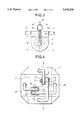
- FIG. 2A is a partial enlarged section of the first embodiment of the hydrostatic anti-vibration system of FIG. 1B;
- FIG. 2B is a section taken along line B--B of FIG. 2A;
- FIG. 3 is a section similar to FIG. 2A but showing a modification of the first embodiment of the hydrostatic anti-vibration system according to the invention
- FIG. 4 is a plan view of a second embodiment of the hydrostatic anti-vibration system according to the present invention.
- FIG. 5 is a plan view of a third embodiment of the hydrostatic anti-vibration system according to the present invention.
- FIG. 6A is a plan view of the fourth embodiment of the hydrostatic anti-vibration system according to the present invention.
- FIG. 6B is a section taken along line C--C of FIG. 6A;
- FIG. 7 is a plan view of the fifth embodiment of the hydrostatic anti-vibration system according to the present invention.
- FIG. 8 is a sectional side elevation of the conventional hydrostatic anti-vibration system.
- FIGS. 1A and 1B show the first embodiment of a hydrostatic anti-vibration system according to the present invention.
- the anti-vibration system includes a main tank 1 and a pair of intermediate tank portions 2 which are arranged in opposition to each other across the main tank 1.
- Each of the intermediate tank portions 2 is communicated with the main tank 1 via a respective pair of communication ducts 3.
- the main tank 1 comprises a flat rectangular main tank body 4 and a hollow vertical extension 5 upwardly extended from the peripheral edge of the main tank body 4 and extending throughout the entire periphery thereof. Therefore, the main tank 1 is constructed in generally rectangular or dish-shaped configuration with a recessed central portion.
- the tank 1 is adapted to be installed on the roof or top or so forth of a construction or building.
- Water 6 as a working fluid or anti-vibration medium fills the entire interior space of the main tank, body 4 and is further filled to an intermediate height level of the vertical extension 5.
- Respective pairs of portions of the vertical extension 5 positioned in opposition to each other are adapted to serve for suppression of vibration exerted in respective directions perpendicular to the longitudinal directions thereof.
- one pair of portions of the vertical extension 5 suppresses vibrations in rearward and forward horizontal directions, and the other pair suppresses vibrations in left and right horizontal directions.
- Adjacent portions of the vertical extension 5 are blocked from communication to each other so that the action of the water for suppressing vibration in one horizontal direction will not affect suppression of vibration in the other horizontal direction.
- Respective portions of the vertical extension 5 are closed at the top.
- Each pair of the portions of the vertical extension 5 are communicated with one of the intermediate tank portions 2 via the respective pair of communication ducts 3 with respective hydropneumatic damping mechanisms described below.
- Each intermediate tank portion 2 is an enclosed tank with a rounded lower half.
- a partitioning plate 7 is disposed within the interior space of the intermediate tank portion 2 depending from the ceiling thereof at the center portion so that a substantially U-shaped water flow path is defined in the intermediate tank portion.
- Water 8 is filled in the intermediate tank portion 2 to a level high than the lower end of the partitioning plate 7.
- a rotary shaft 9 is rotatably supported at the lower end of the partitioning plate 7 to extend horizontally.
- the rotary shaft 9 is rigidly connected to a pivotal plate 10 for pivotal movement within the rounded lower half of the intermediate tank portion 2.
- the pivotal plate 10 thus constructed pivots in response to flowing motion of water 8 induced by vibration of the construction.
- the rotary shaft 9 extends from the intermediate tank portion 2.
- a coil spring 11 is disposed between the extended end of the rotary shaft 9 and the stationary wall of the intermediate tank portion 2 and forms a damper for exerting a spring force for providing a resistance against rotary motion of the rotary shaft 9.
- the rotary shaft 9 is rotationally supported by water tight seal bearings 12 provided at both sides of the intermediate tank portion 2.
- a threaded shaft 13 To the extended end of the rotary shaft 9 positioned outside of the intermediate tank portion 2 is connected a threaded shaft 13 to depend perpendicularly from the rotary shaft 9.
- the threaded shaft 13 carries a pendulum 14 which provides a rotational inertia moment and a restoration force toward an initial position.
- the pendulum 14 is threadingly movable along the threaded shaft 13 for varying a lever ratio and thereby varying the natural frequency.
- Fastening nuts 15 are provided at both axial ends of the pendulum 14.
- each pivotal plate 10 is determined by a combination of the spring coefficient of the respective coil spring 11 and the rotational inertia force and restoration force to be induced by the respective pendulum 14. This further determines the vibration frequency of the overall anti-vibration system.
- the inertia moment to be generated on the pendulum 14 is variable depending upon the axial position thereof on the threaded shaft 13.
- the inertia force thus generated by the pendulum is combined with the resistance against rotation of the rotary shaft 9 exerted by the coil spring 11.
- the rotational inertia moment become smaller so that the resistance against rotation of the rotary shaft 9 becomes smaller
- the rotational inertial moment of the pendulum becomes greater to provide greater resistance against rotation of the rotary shaft 9.
- the natural frequency is variable depending upon the resistance against the rotation of the rotary shaft 9.
- the ducts 3 are connected to mutually opposing portions of the vertical extension 5.
- the phases of rocking motion of the water flow between the associated pairs of the portions of the vertical extension 5 are mutually opposite.
- the ducts 3 illustrated in FIG. 1B as shown by the arrows, the direction of the fluid force of water and the direction of compression of air is serial throughout the system, including through the substantially U-shaped flow path in the intermediate tank portion. Therefore, cancellation of the fluid forces due to opposite phases of action, as occur in the prior art, can be successfully avoided.
- motion of water portions 6 and 8 in the main tank 1 and in the intermediate tank portion 2 are synchronized with each other, a high anti-vibration effect can be achieved with a small size system.
- FIG. 3 shows a modification of the foregoing first embodiment of the hydrostatic anti-vibration system according to the invention.
- the rotational inertial moment and the restoration force to be applied by the pendulum 14 acts in a direction opposite to the direction of the spring force of the coil spring 11.
- the threaded shaft 13 is extended vertically upwardly from the extending end of the rotary shaft 9.
- the pendulum 14 is engaged to the threaded shaft 13 for axial threading adjusted movement therealong.
- Opposite axial ends of the pendulum 14 are fixed by fastening nuts 15.
- the inertia force and restoration force to be generated by the pendulum at the occurrence of vibration is opposite to the direction of the spring force of the coil spring 11. Therefore, such construction will permit adjustment of the vibration frequency of the system by shifting the pendulum 14 along the threaded shaft 13, and thereby adjusting the counter force against the spring force.
- the pendulum 14 is mounted on the threaded shaft 13 and positioned at a position closest to the rotary shaft 9. Then, by manually swinging the threaded shaft 13 for free swinging motion, the vibration period is again measured. Then, by shifting the axial position of the pendulum 14 by threadingly shifting the fastening nuts 15, measurement of the vibration period is measured repeatedly at different axial positions of the pendulum 14.
- the axial position of the pendulum 14, where synchronization of the pivotal motion of the pivotal plate 10 to the natural period of the construction can be established. Then, at the synchronized position, it is confirmed with a vibration gauge positioned at the top end of the construction or building that the amplitude of the vibration of the construction becomes minimum.
- the pendulum 14 is fixed at the axial position where synchronization is established by tightening the fastening nuts 15.
- a different weight of pendulum 14 may be used so that synchronization can be established within a range of the adjustable stroke of the threaded shaft 13.
- water 6 collides on a wall of the tank 1 with a delay to the natural period or vibratory phase of the vibration of the construction.
- the water level in each hollow portion of vertical extension 5 is varied to increase or decrease the air pressure therein.
- Variation of the air pressure at each air containing space of each portion of the hollow vertical extension 5 is introduced at both sides of the substantially U-shaped water flow path in the respective intermediate tank portion 2 to cause rocking water flow along the U-shaped flow path thereof.
- the spring biased pivotal plate 10 serves to provide resistance. This resistance cancels vibratory energy of the construction.
- the displacement characteristics or flow resistance characteristics of the pivotal plate 10 can be easily adjusted by varying the axial position of the pendulum 14 or by adjusting the spring coefficient of the coil spring 11.
- the anti-vibration characteristics of the overall system can be synchronized with the natural frequency of the construction or the building.
- the intermediate tank portions 2 can be placed at any arbitrary positions.
- the intermediate tank portion 2 can be placed outside of the main tank, adjustment of the flow resistance for the rotary plate 10 can be facilitated.
- two intermediate tank portions 2 are employed for obtaining anti-vibration effect for two horizontal directions, the construction of the anti-vibration system can be simplified.
- adjustment of the anti-vibration characteristics against one direction of horizontal vibration can be done by adjusting only one portion, adjustment of the characteristics adapting to the vibration characteristics of the construction or building becomes easier.
- the coil spring 11 is a primary element for producing resistance against pivotal movement of the pivotal plate 10 and the pendulum 14 is employed as an element for adjusting the anti-vibration characteristics, it is possible to employ only pendulum 14 for producing the resistance against pivotal movement of the pivotal plate 10 and for adjustment of the anti-vibration characteristics. Also, while the resistance against pivotal motion of the pivotal plate 10 is provided by the coil spring 11, it is possible that the pivotal plate can be coupled with an active drive such as a motor, hydraulic actuator and so forth for actively suppressing vibration of the construction.
- two intermediate tank portions 2 are positioned in the recessed central portion of the main tank body 4 surrounded by the vertical extension 5.
- Two spaces defined in each intermediate tank portion 2 by the respective partitioning plate 7 are communicated with respective mutually opposing portions of the vertical extension 5 through ducts 3 to cause fluid flow in reversed phases. Therefore, the fluid forces in two spaces of one intermediate tank portion 2 are opposite in phase to the adjacent portions of the vertical extension 5, thereby certainly avoiding mutual cancellation. Since the intermediate tank portions 2 are arranged on the main tank body 4, the length of the ducts 3 can be shortened and the overall size of the anti-vibration system can be made smaller.
- FIG. 5 shows the third embodiment of the hydrostatic anti-vibration system according to the present invention.
- Two spaces defined in each intermediate tank portion 2 by the respective partitioning plate 7 are communicated with respective mutually opposing portions of the vertical extension 5 through the ducts 3 to cause fluid flow in the same phase.
- FIGS. 6A and 6B show the fourth embodiment of the hydrostatic anti-vibration system according to the invention.
- Four vertical extensions 5 are provided at respective four corners of the main tank body 4 in communication with the latter.
- Four intermediate tank portions 2 are provided between adjacent vertical extensions 5.
- FIG. 7 shows the fifth embodiment of the hydrostatic anti-vibration system according to the invention.
- the bottom of the intermediate tank portion 2 and the main tank body 4 are communicated through a conduit 16 so that the water levels in the vertical extensions 5 and in the intermediate tank portion 2 are constantly maintained equal.
- the diameter of the conduit 16 is selected in such a manner that the water levels in the vertical extensions 5 and in the intermediate tank portion 2 are equal in the static state, but that the anti-vibration effect will not be affected, the small diameter of the conduit 16 provides sufficient water flow restriction. Even when water flows through the ducts 3 between the main tank body 4 and the intermediate tank portions 2 to cause a difference of the water levels due to large amplitude vibration, water will flow through the conduit 16 to gradually equalize the water levels.
- connection between the vertical extensions 5 and two spaces defined in the respective intermediate tank portion 2 may be established in equal phase (as shown by solid lines) or in reverse phase (as shown by broken lines).
Landscapes
- Engineering & Computer Science (AREA)
- Architecture (AREA)
- Business, Economics & Management (AREA)
- Emergency Management (AREA)
- Environmental & Geological Engineering (AREA)
- Civil Engineering (AREA)
- Structural Engineering (AREA)
- Vibration Prevention Devices (AREA)
- Buildings Adapted To Withstand Abnormal External Influences (AREA)
Abstract
Description
Claims (15)
Applications Claiming Priority (10)
| Application Number | Priority Date | Filing Date | Title |
|---|---|---|---|
| JP5-300500 | 1993-11-30 | ||
| JP30050293A JP2891619B2 (en) | 1993-11-30 | 1993-11-30 | Fluid damping device |
| JP30050093A JPH07150803A (en) | 1993-11-30 | 1993-11-30 | Fluid type vibration-proof device |
| JP5-300501 | 1993-11-30 | ||
| JP5-300502 | 1993-11-30 | ||
| JP5300501A JP2972512B2 (en) | 1993-11-30 | 1993-11-30 | Fluid damping device |
| JP135194A JP2891626B2 (en) | 1994-01-11 | 1994-01-11 | Fluid damping device |
| JP6-001351 | 1994-01-11 | ||
| JP6-006214 | 1994-01-25 | ||
| JP621494A JP2832144B2 (en) | 1994-01-25 | 1994-01-25 | Adjustment method of passive vibration suppression device |
Publications (1)
| Publication Number | Publication Date |
|---|---|
| US5542220A true US5542220A (en) | 1996-08-06 |
Family
ID=27518099
Family Applications (1)
| Application Number | Title | Priority Date | Filing Date |
|---|---|---|---|
| US08/297,886 Expired - Fee Related US5542220A (en) | 1993-11-30 | 1994-08-30 | Hydrostatic anti-vibration system and adjusting method therefor |
Country Status (1)
| Country | Link |
|---|---|
| US (1) | US5542220A (en) |
Cited By (11)
| Publication number | Priority date | Publication date | Assignee | Title |
|---|---|---|---|---|
| US6457285B1 (en) | 1999-09-09 | 2002-10-01 | Hector Valencia | Aseismic system |
| US6484458B1 (en) * | 1999-05-19 | 2002-11-26 | Jang-Ho Park | Method of and apparatus for preventing structure from collapsing due to earthquake |
| US20040068125A1 (en) * | 2000-12-19 | 2004-04-08 | Senal Angel Castillo | Foundation building system with antiseismic plates |
| US20040118057A1 (en) * | 2002-12-09 | 2004-06-24 | Sanders Royden C. | Siesmic sensitive mass motion power converter for protecting structures from earthquakes |
| US20040201153A1 (en) * | 2003-04-09 | 2004-10-14 | Yung-Hsiang Chen | Propeller-controlled active tuned-liquid-column damper |
| US20070114799A1 (en) * | 2005-11-18 | 2007-05-24 | Andre Riesberg | Systems and methods for damping a displacement of a wind turbine tower |
| DE102013010595A1 (en) * | 2013-06-26 | 2014-12-31 | Rheinisch-Westfälische Technische Hochschule Aachen | Liquid columns damping system |
| CN109610673A (en) * | 2019-02-01 | 2019-04-12 | 青岛理工大学 | Active Moment of Inertia Drive Control System |
| CN117739060A (en) * | 2023-12-18 | 2024-03-22 | 东南大学 | Suspension bridge sling support type vibration reduction system |
| US20250010958A1 (en) * | 2022-11-14 | 2025-01-09 | Dalian University Of Technology | Air-liquid dual control anti-rolling control system for floating offshore wind turbine in offshore deep sea |
| US12352331B2 (en) | 2020-05-12 | 2025-07-08 | Nok Corporation | Vibration damper, vibration damping apparatus, mounting method of vibration damper, and vibration damping method |
Citations (4)
| Publication number | Priority date | Publication date | Assignee | Title |
|---|---|---|---|---|
| US4266379A (en) * | 1979-03-06 | 1981-05-12 | Hector Valencia Aguilar | Aseismic system for structure foundation |
| US4873798A (en) * | 1987-11-17 | 1989-10-17 | Shimizu Construction Co., Ltd. | Apparatus for suppressing vibration of structure |
| US4922671A (en) * | 1987-11-17 | 1990-05-08 | Shimizu Construction Co., Ltd. | Method for effectively restraining response of a structure to outside disturbances and apparatus therefor |
| US4951441A (en) * | 1987-12-01 | 1990-08-28 | Mitshi Kensetsu Kabushiki Kaisha | Damping device in a structure and damping construction and damping method using those devices |
-
1994
- 1994-08-30 US US08/297,886 patent/US5542220A/en not_active Expired - Fee Related
Patent Citations (4)
| Publication number | Priority date | Publication date | Assignee | Title |
|---|---|---|---|---|
| US4266379A (en) * | 1979-03-06 | 1981-05-12 | Hector Valencia Aguilar | Aseismic system for structure foundation |
| US4873798A (en) * | 1987-11-17 | 1989-10-17 | Shimizu Construction Co., Ltd. | Apparatus for suppressing vibration of structure |
| US4922671A (en) * | 1987-11-17 | 1990-05-08 | Shimizu Construction Co., Ltd. | Method for effectively restraining response of a structure to outside disturbances and apparatus therefor |
| US4951441A (en) * | 1987-12-01 | 1990-08-28 | Mitshi Kensetsu Kabushiki Kaisha | Damping device in a structure and damping construction and damping method using those devices |
Cited By (15)
| Publication number | Priority date | Publication date | Assignee | Title |
|---|---|---|---|---|
| US6484458B1 (en) * | 1999-05-19 | 2002-11-26 | Jang-Ho Park | Method of and apparatus for preventing structure from collapsing due to earthquake |
| US6457285B1 (en) | 1999-09-09 | 2002-10-01 | Hector Valencia | Aseismic system |
| US20040068125A1 (en) * | 2000-12-19 | 2004-04-08 | Senal Angel Castillo | Foundation building system with antiseismic plates |
| US20040118057A1 (en) * | 2002-12-09 | 2004-06-24 | Sanders Royden C. | Siesmic sensitive mass motion power converter for protecting structures from earthquakes |
| US20040201153A1 (en) * | 2003-04-09 | 2004-10-14 | Yung-Hsiang Chen | Propeller-controlled active tuned-liquid-column damper |
| US6857231B2 (en) * | 2003-04-09 | 2005-02-22 | Yung-Hsiang Chen | Propeller-controlled active tuned-liquid-column damper |
| US20070114799A1 (en) * | 2005-11-18 | 2007-05-24 | Andre Riesberg | Systems and methods for damping a displacement of a wind turbine tower |
| DE102013010595A1 (en) * | 2013-06-26 | 2014-12-31 | Rheinisch-Westfälische Technische Hochschule Aachen | Liquid columns damping system |
| US20160130804A1 (en) * | 2013-06-26 | 2016-05-12 | Rheinisch-Westfälische Technische Hochschule Aachen | Liquid column damping system |
| US9580903B2 (en) * | 2013-06-26 | 2017-02-28 | Rheinisch-Westfaelische-Technische Hochschule Aachen | Liquid column damping system |
| CN109610673A (en) * | 2019-02-01 | 2019-04-12 | 青岛理工大学 | Active Moment of Inertia Drive Control System |
| CN109610673B (en) * | 2019-02-01 | 2023-11-24 | 青岛理工大学 | Active inertia drive control system |
| US12352331B2 (en) | 2020-05-12 | 2025-07-08 | Nok Corporation | Vibration damper, vibration damping apparatus, mounting method of vibration damper, and vibration damping method |
| US20250010958A1 (en) * | 2022-11-14 | 2025-01-09 | Dalian University Of Technology | Air-liquid dual control anti-rolling control system for floating offshore wind turbine in offshore deep sea |
| CN117739060A (en) * | 2023-12-18 | 2024-03-22 | 东南大学 | Suspension bridge sling support type vibration reduction system |
Similar Documents
| Publication | Publication Date | Title |
|---|---|---|
| US5542220A (en) | Hydrostatic anti-vibration system and adjusting method therefor | |
| CA1314570C (en) | Damping device for tower-like structure | |
| US5439082A (en) | Hydraulic inertial vibration isolator | |
| JP2007504415A (en) | Active vibration isolation actuator configuration with inertial reference mass | |
| JPH03149424A (en) | Mount provided with inertia track with adjustable length | |
| WO2015017792A1 (en) | Method for suppression of resonant vibrations in subsea pipelines | |
| US4603843A (en) | Rubber mount with elastic control | |
| CA2489103C (en) | Vibration isolator | |
| JPH09151986A (en) | U-shaped tank type dynamic vibration absorbing device | |
| US20080041676A1 (en) | Air spring with magneto-rheological fluid gasket for suppressing vibrations | |
| JPH08100545A (en) | Vibration control device for steel frame structure | |
| JP2972512B2 (en) | Fluid damping device | |
| JP3064088B2 (en) | Damping device | |
| JP3040627B2 (en) | Fluid damping device | |
| US20080079204A1 (en) | Self-aligning air-spring for suppressing vibrations | |
| JPH04161678A (en) | Damping device of building | |
| JP3564594B2 (en) | Anti-vibration device | |
| JPS61228139A (en) | Vibration damping apparatus | |
| JP2516746B2 (en) | Fluid filled vibration isolation device | |
| JP2841487B2 (en) | Structure damping device | |
| JPS63151725A (en) | Structure having regulatable vibration transmittivity | |
| JP2667751B2 (en) | Fluid damping device | |
| JPH04266639A (en) | Fluid type damping device | |
| JP3884835B2 (en) | Isolation floor device | |
| JP3025030B2 (en) | Damping tank device |
Legal Events
| Date | Code | Title | Description |
|---|---|---|---|
| AS | Assignment |
Owner name: OBAYASHI CORPORATION, JAPAN Free format text: ASSIGNMENT OF ASSIGNORS INTEREST;ASSIGNORS:YOSHIMURA, MITSUHIRO;FUJITA, KAZUNOBU;TERAMURA, AKIRA;REEL/FRAME:007127/0786 Effective date: 19940523 Owner name: MITSUBISHI JUKOGYO KABUSHIKI KAISHA, JAPAN Free format text: ASSIGNMENT OF ASSIGNORS INTEREST;ASSIGNORS:YOSHIMURA, MITSUHIRO;FUJITA, KAZUNOBU;TERAMURA, AKIRA;REEL/FRAME:007127/0786 Effective date: 19940523 |
|
| FEPP | Fee payment procedure |
Free format text: PAYOR NUMBER ASSIGNED (ORIGINAL EVENT CODE: ASPN); ENTITY STATUS OF PATENT OWNER: LARGE ENTITY |
|
| FPAY | Fee payment |
Year of fee payment: 4 |
|
| REMI | Maintenance fee reminder mailed | ||
| LAPS | Lapse for failure to pay maintenance fees | ||
| FP | Lapsed due to failure to pay maintenance fee |
Effective date: 20040806 |
|
| STCH | Information on status: patent discontinuation |
Free format text: PATENT EXPIRED DUE TO NONPAYMENT OF MAINTENANCE FEES UNDER 37 CFR 1.362 |