US5538062A - Pnuematic tire inflation system - Google Patents
Pnuematic tire inflation system Download PDFInfo
- Publication number
- US5538062A US5538062A US08/289,454 US28945494A US5538062A US 5538062 A US5538062 A US 5538062A US 28945494 A US28945494 A US 28945494A US 5538062 A US5538062 A US 5538062A
- Authority
- US
- United States
- Prior art keywords
- arm
- coupling
- air
- wheel
- elongate support
- Prior art date
- Legal status (The legal status is an assumption and is not a legal conclusion. Google has not performed a legal analysis and makes no representation as to the accuracy of the status listed.)
- Expired - Lifetime
Links
Images

Classifications
-
- B—PERFORMING OPERATIONS; TRANSPORTING
- B60—VEHICLES IN GENERAL
- B60C—VEHICLE TYRES; TYRE INFLATION; TYRE CHANGING; CONNECTING VALVES TO INFLATABLE ELASTIC BODIES IN GENERAL; DEVICES OR ARRANGEMENTS RELATED TO TYRES
- B60C23/00—Devices for measuring, signalling, controlling, or distributing tyre pressure or temperature, specially adapted for mounting on vehicles; Arrangement of tyre inflating devices on vehicles, e.g. of pumps or of tanks; Tyre cooling arrangements
- B60C23/001—Devices for manually or automatically controlling or distributing tyre pressure whilst the vehicle is moving
- B60C23/003—Devices for manually or automatically controlling or distributing tyre pressure whilst the vehicle is moving comprising rotational joints between vehicle-mounted pressure sources and the tyres
- B60C23/00345—Details of the rotational joints
-
- B—PERFORMING OPERATIONS; TRANSPORTING
- B60—VEHICLES IN GENERAL
- B60C—VEHICLE TYRES; TYRE INFLATION; TYRE CHANGING; CONNECTING VALVES TO INFLATABLE ELASTIC BODIES IN GENERAL; DEVICES OR ARRANGEMENTS RELATED TO TYRES
- B60C23/00—Devices for measuring, signalling, controlling, or distributing tyre pressure or temperature, specially adapted for mounting on vehicles; Arrangement of tyre inflating devices on vehicles, e.g. of pumps or of tanks; Tyre cooling arrangements
- B60C23/001—Devices for manually or automatically controlling or distributing tyre pressure whilst the vehicle is moving
- B60C23/003—Devices for manually or automatically controlling or distributing tyre pressure whilst the vehicle is moving comprising rotational joints between vehicle-mounted pressure sources and the tyres
- B60C23/00305—Wheel circumventing supply lines, e.g. not through or about the axles
-
- B—PERFORMING OPERATIONS; TRANSPORTING
- B60—VEHICLES IN GENERAL
- B60C—VEHICLE TYRES; TYRE INFLATION; TYRE CHANGING; CONNECTING VALVES TO INFLATABLE ELASTIC BODIES IN GENERAL; DEVICES OR ARRANGEMENTS RELATED TO TYRES
- B60C23/00—Devices for measuring, signalling, controlling, or distributing tyre pressure or temperature, specially adapted for mounting on vehicles; Arrangement of tyre inflating devices on vehicles, e.g. of pumps or of tanks; Tyre cooling arrangements
- B60C23/001—Devices for manually or automatically controlling or distributing tyre pressure whilst the vehicle is moving
- B60C23/003—Devices for manually or automatically controlling or distributing tyre pressure whilst the vehicle is moving comprising rotational joints between vehicle-mounted pressure sources and the tyres
- B60C23/00309—Devices for manually or automatically controlling or distributing tyre pressure whilst the vehicle is moving comprising rotational joints between vehicle-mounted pressure sources and the tyres characterised by the location of the components, e.g. valves, sealings, conduits or sensors
- B60C23/00318—Devices for manually or automatically controlling or distributing tyre pressure whilst the vehicle is moving comprising rotational joints between vehicle-mounted pressure sources and the tyres characterised by the location of the components, e.g. valves, sealings, conduits or sensors on the wheels or the hubs
Definitions
- the present invention is directed to a pneumatic tire inflation system for attachment to a rotating wheel having outwardly directed studs for inflating a tire thereon.
- the present invention is directed to a system which can be attached to and supply air to a tire while the wheel is rotating. This is particularly advantageous for providing temporary air supply to the tire to allow the vehicle to continue to a facility where the tire may be replaced.
- the present invention is directed to a pneumatic tire inflation system for attachment to rotating wheels having outwardly directed studs.
- the system includes an elongate support having first and second ends and the first end includes threads for engaging a stud on a wheel for supporting the support.
- a rotatably adjustable arm having first and second ends is provided with the first end connected to the second end of the elongate support.
- a rotatably adjustable connection is provided between the second end of the support and the first end of the arm for rotatably adjusting the position of the second end of the arm.
- a rotatable air coupling is connected to the second end of the arm.
- the coupling includes first and second parts sealably and rotatably movable relative to each other.
- An air supply line is connected to the first part and an air outlet line is connected to the second part for supplying air to a tire on the wheel.
- a still further object is wherein the second end of the arm is adjustable to the center line of the wheel.
- the first part of the coupling is a tubular member having a side port connected to the air supply line.
- Yet a further object is wherein the arm is positioned perpendicular to the elongate support and the coupling is positioned perpendicular to the arm.
- a further object is wherein the rotatably adjustable connection includes a pivot screw threadably connected to the second end of the elongate support.
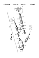
- FIG. 1 is a schematic and perspective elevational view of the present system attached to the wheel of a vehicle
- FIG. 2 is a an enlarged elevational view, in cross section, of the air coupling used in the system.
- FIG. 3 is an enlarged fragmentary, exploded view of the connections of the presently invention.
- the reference numeral 10 generally indicates a wheel of a vehicle, such as a truck, having a rim 12 with a pneumatic tire 14 thereon, and a plurality of outwardly directed studs, such as studs 16.
- a wheel 10 is conventional.
- wheels 10 are not easy to change, and generally require specialized road service. Therefore, it is desirable to provide a temporary air inflation system for attachment to the wheel 10 for providing air to the tire 14 to enable the vehicle to continue to a convenient location, if the tire leak is not too severe, for replacement of the tire 14.
- the reference numeral 20 generally indicates the pneumatic tire air inflation system of the present invention, and generally includes an elongate support 22, a rotatably adjustable arm 24, a rotatable air coupling 26, an air supply 28, and an air outlet line 30.
- the elongate support 22 has a first end 32 and a second end 34.
- the first end 32 includes internal threads 36 for engaging one of the studs 16 for supporting the support 22 from the wheel 10.
- the rotatably adjustable arm 24 includes a first end 38 and a second end 40 and the first end 38 is adjustably connected to the second end 34 of the elongate support 22.
- a rotatably adjustable connection is provided between the second end 34 of the elongate support 22 and the first end 38 of the arm 24 for rotatably adjusting the position of the second end 40 of the arm, preferably to bring it into alignment with the center line 42 of the axis of the wheel 10.
- the rotatably adjustable connection may include a pivot screw 44 which is inserted through a washer 45 and an opening 46 in the first end 38 of the arm 24 and is threadably secured in threads 48 in the second end 34 of the elongate support 22.
- the angular position of the arm 24 may be adjusted prior to tightening the screw 44.
- a cross opening 50 may be provided in the elongate support 22 for insertion of a tool for conveniently threading the elongate support 22 onto the stud 16.
- the tool may be an Allenhead wrench which can also be used to secure the screw 44 to the second end 34 of the elongate support 22.
- the rotatable air coupling 26 is connected to the second end 40 of the arm 24 and is preferably positioned on the center line 42 of the wheel 10.
- the rotary union 26 includes a first part 52 and a second part 54, each of which is adapted to receive an air connection for connection to an air passageway 56.
- the parts 52 and 54 are rotatable to each other through bearings 58 and are sealable relative to each other by a seal 60.
- the first part 52 includes a port 62 for connection to an air supply line 64.
- the air passageway 56 extends through the first and second parts 52 and 54 and is in communication with an air outlet line 30 which is connected to the second part 54.
- the air outlet line 30 is connected to the tire 14 valve stem 66.
- the air supply line 64 forms a portion of the air supply 28 which may include an air regulator 68, gauge 70, and a connection 72 to an air supply, such as a compressor (not shown) on the vehicle.
- the air supply line 64 is supportable by a suitable means (not shown) connected to the vehicle.
- the air supply is generally a continuous air supply and the regulator 68 is used to shut off the air supply to the tire 14 in the event that it reaches a predetermined amount, for example only, such as 80 psi.
- the air inflation system 20 is quickly and easily connectible to the wheel 10 as the elongate support 22 is threaded upon a stud 16, the rotational position of the arm 24 is set and secured by the screw 44 to place the coupling on the center line 22 of the wheel 10, the outlet line 30 is connected to the valve stem 66, and the connector 72 is connected to the vehicle air supply. Since the arm 24 is perpendicular to the support 22 and the coupling 26 is perpendicular to the arm 24, the first part 52 of the coupling 26 will rotate as the wheel 10 rotates while still supplying air to the rotating wheel 10. By the connection of line 64 to the side port 62, the line 64 may be stationary while the part 52 rotates. When the desired location is reached, the system 10 is quickly and easily disconnected.
Landscapes
- Engineering & Computer Science (AREA)
- Mechanical Engineering (AREA)
- Tires In General (AREA)
Abstract
Description
Claims (5)
Priority Applications (3)
| Application Number | Priority Date | Filing Date | Title |
|---|---|---|---|
| US08/289,454 US5538062A (en) | 1994-08-12 | 1994-08-12 | Pnuematic tire inflation system |
| AU32383/95A AU3238395A (en) | 1994-08-12 | 1995-08-04 | Pneumatic tire inflation system |
| PCT/US1995/009888 WO1996005077A1 (en) | 1994-08-12 | 1995-08-04 | Pneumatic tire inflation system |
Applications Claiming Priority (1)
| Application Number | Priority Date | Filing Date | Title |
|---|---|---|---|
| US08/289,454 US5538062A (en) | 1994-08-12 | 1994-08-12 | Pnuematic tire inflation system |
Publications (1)
| Publication Number | Publication Date |
|---|---|
| US5538062A true US5538062A (en) | 1996-07-23 |
Family
ID=23111608
Family Applications (1)
| Application Number | Title | Priority Date | Filing Date |
|---|---|---|---|
| US08/289,454 Expired - Lifetime US5538062A (en) | 1994-08-12 | 1994-08-12 | Pnuematic tire inflation system |
Country Status (3)
| Country | Link |
|---|---|
| US (1) | US5538062A (en) |
| AU (1) | AU3238395A (en) |
| WO (1) | WO1996005077A1 (en) |
Cited By (48)
| Publication number | Priority date | Publication date | Assignee | Title |
|---|---|---|---|---|
| US5954084A (en) * | 1996-04-08 | 1999-09-21 | Conroy, Sr.; Joseph P. | Pneumatic control |
| US6105645A (en) * | 1998-05-14 | 2000-08-22 | Ingram; Anthony L. | Rotary union assembly for use in air pressure inflation systems for tractor trailer tires |
| US6161565A (en) * | 1996-04-08 | 2000-12-19 | Conroy, Sr.; Joseph P. | Pneumatic control |
| US6260595B1 (en) * | 1999-08-04 | 2001-07-17 | Meritor Heavy Vehicle Systems, Llc | Unitized hub cap |
| US6325124B1 (en) * | 2000-02-03 | 2001-12-04 | Col-Ven S.A. | Pneumatic rotary wheel coupling |
| US6394159B1 (en) | 2001-01-26 | 2002-05-28 | Meritor Heavy Vehicle Technology, Llc | Hub cap filter for tire inflation system |
| US6705369B1 (en) * | 2002-02-22 | 2004-03-16 | Vincent T. Russell | Deformable valve extension support with retention flanges |
| US20050161136A1 (en) * | 2004-01-27 | 2005-07-28 | Hayes Brian D. | Central tire inflation system for drive axle |
| US20060018766A1 (en) * | 2004-07-21 | 2006-01-26 | Stanczak Edmund A | Tire inflation system with pressure limiter |
| US7201066B1 (en) | 2005-03-30 | 2007-04-10 | The Board Of Regents For Oklahoma State University | System for automatic tire inflation |
| AT503792B1 (en) * | 2006-08-28 | 2008-01-15 | Ventrex Automotive Gmbh | TIRE PRESSURE regulation PLANT |
| US20080127773A1 (en) * | 2006-11-13 | 2008-06-05 | Solie John B | Apparatus for delivering air through powered axle assemblies |
| US7530379B1 (en) * | 2002-04-10 | 2009-05-12 | John Henry Becker | Tire inflation system |
| US8028732B1 (en) | 1998-05-14 | 2011-10-04 | Airgo Ip, Llc | Tire inflation system |
| US20120025594A1 (en) * | 2006-12-15 | 2012-02-02 | Oto Melara S.P.A. Con Unico Socio | Power-driven wheel for a military vehicle |
| WO2012012617A3 (en) * | 2010-07-21 | 2013-07-25 | Aperia Technologies | Tire inflation system |
| US8919401B2 (en) | 2003-09-09 | 2014-12-30 | Equalaire Systems, Inc. | Wheel end assembly high-temperature warning system |
| US9121401B2 (en) | 2012-03-20 | 2015-09-01 | Aperia Technologies, Inc. | Passive pressure regulation mechanism |
| US9604157B2 (en) | 2013-03-12 | 2017-03-28 | Aperia Technologies, Inc. | Pump with water management |
| US10005325B2 (en) | 2016-03-31 | 2018-06-26 | Airgo Ip, Llc | Tire pressure management system |
| US10086660B1 (en) | 2016-03-31 | 2018-10-02 | Airgo Ip, Llc | Tire pressure management system |
| US10144254B2 (en) | 2013-03-12 | 2018-12-04 | Aperia Technologies, Inc. | Tire inflation system |
| US10245908B2 (en) | 2016-09-06 | 2019-04-02 | Aperia Technologies, Inc. | System for tire inflation |
| US10343467B1 (en) | 2016-11-08 | 2019-07-09 | Airgo Ip, Llc | Tire inflation system safety valve |
| US10543849B2 (en) | 2016-03-31 | 2020-01-28 | Airgo Ip, Llc | Vehicle operational diagnostics and condition response system |
| US10596862B1 (en) | 2016-03-31 | 2020-03-24 | Airgo Ip, Llc | Dynamic wheel management system |
| US10596863B1 (en) | 2016-03-31 | 2020-03-24 | Airgo Ip, Llc | Tire pressure management system |
| US10596864B1 (en) | 2016-11-08 | 2020-03-24 | Airgo Ip, Llc | Tire inflation system safety valve |
| US10647169B1 (en) | 2016-03-31 | 2020-05-12 | Airgo Ip, Llc | Tire pressure management system |
| US10668777B2 (en) | 2010-07-29 | 2020-06-02 | Equalaire Systems, Inc. | Steer axle tire inflation system |
| US10703135B2 (en) * | 2015-06-15 | 2020-07-07 | Stemco Products, Inc. | Inflation hubcap installation system |
| US10766316B1 (en) | 2016-11-08 | 2020-09-08 | Airgo Ip, Llc | Combination in line tire pressure measurement sensor and tire pressure safety valve |
| US11203237B2 (en) * | 2018-03-19 | 2021-12-21 | Dana Heavy Vehicle Systems Group, Llc | Assembly for a tire inflation system |
| US11254373B2 (en) | 2017-06-24 | 2022-02-22 | FlowBelow Aero, Inc. | Aerodynamic systems and fairings with fairing caps |
| US11254170B2 (en) | 2017-04-13 | 2022-02-22 | Tesla, Inc. | Automatic tire inflation system with thru-hub air feed |
| US11273877B2 (en) | 2017-07-30 | 2022-03-15 | FlowBelow Aero, Inc. | Rotatable aerodynamic fairing system |
| US11352073B2 (en) | 2017-07-12 | 2022-06-07 | FlowBelow Aero, Inc. | Aerodynamic toolbox assembly |
| US11453258B2 (en) | 2013-03-12 | 2022-09-27 | Aperia Technologies, Inc. | System for tire inflation |
| US11642920B2 (en) | 2018-11-27 | 2023-05-09 | Aperia Technologies, Inc. | Hub-integrated inflation system |
| US11654928B2 (en) | 2020-07-28 | 2023-05-23 | Airgo Ip, Llc | Vehicle operational diagnostics, condition response, vehicle pairing, and blind spot detection system |
| US11667338B2 (en) | 2012-11-01 | 2023-06-06 | FlowBelow Aero, Inc. | Aerodynamic system and adjustable fairings |
| US11752810B2 (en) | 2020-07-28 | 2023-09-12 | Airgo Ip, Llc | Steer axle pressure management system |
| US11767064B2 (en) | 2021-01-12 | 2023-09-26 | FlowBelow Aero, Inc. | Spring-biased mud flap hanger with improved pivoting motion guidance |
| US11932060B2 (en) * | 2016-11-04 | 2024-03-19 | FlowBelow Aero, Inc. | Chassis mounted energy extraction and delivery system |
| US12014583B2 (en) | 2020-07-28 | 2024-06-18 | Airgo Ip, Llc | Vehicle operational diagnostics and trailer health status system combination |
| US12011956B2 (en) | 2017-11-10 | 2024-06-18 | Aperia Technologies, Inc. | Inflation system |
| US12157337B2 (en) | 2018-07-31 | 2024-12-03 | Pressure Systems International, Llc | Digital wheel end assembly temperature monitoring system |
| US12442364B2 (en) | 2023-12-11 | 2025-10-14 | Aperia Technologies, Inc. | Two-stage pump and method of operation |
Families Citing this family (1)
| Publication number | Priority date | Publication date | Assignee | Title |
|---|---|---|---|---|
| US9682599B1 (en) * | 2015-12-09 | 2017-06-20 | The Goodyear Tire & Rubber Company | On-wheel air maintenance system |
Citations (12)
| Publication number | Priority date | Publication date | Assignee | Title |
|---|---|---|---|---|
| US902644A (en) * | 1907-10-29 | 1908-11-03 | Wyatt Boyd | Connection for inflating tires. |
| US1005149A (en) * | 1911-01-17 | 1911-10-10 | Henry W Brink | Automatic valve for pneumatic tires. |
| US1054504A (en) * | 1911-09-07 | 1913-02-25 | Louis Burgraff Jr | Means for tire inflation. |
| US1165057A (en) * | 1915-07-03 | 1915-12-21 | Donald Alvord | Tire-inflating device. |
| US1165876A (en) * | 1914-03-19 | 1915-12-28 | George Goodman | Pressure-indicating mechanism for pneumatic-tired vehicles. |
| US1205504A (en) * | 1915-06-11 | 1916-11-21 | Rees J Jones | Fluid-tight swivel-joint. |
| US2107405A (en) * | 1934-01-25 | 1938-02-08 | Schraders Son Inc | Rotating joint for running inflation |
| US4676289A (en) * | 1984-08-13 | 1987-06-30 | Cherng Yi Su | Automobile tire having retractable tread studs |
| US4685501A (en) * | 1986-03-06 | 1987-08-11 | Williams Donald E | Remotely controlled inflation/deflation valve system for a vehicle tire |
| US4883106A (en) * | 1989-01-19 | 1989-11-28 | Eaton Corporation | Rotary wheel-end assembly for tire inflation system |
| US5080156A (en) * | 1990-02-12 | 1992-01-14 | Bartos Josef A | Vehicle wheel and axle assembly for controlling air pressure in tires with spaces between the bearing elements and the race members included in the air flow path |
| US5097875A (en) * | 1988-08-05 | 1992-03-24 | Compagnie Generale Des Etablissements Michelin-Michelin & Cie | Portable reinflator |
-
1994
- 1994-08-12 US US08/289,454 patent/US5538062A/en not_active Expired - Lifetime
-
1995
- 1995-08-04 WO PCT/US1995/009888 patent/WO1996005077A1/en not_active Ceased
- 1995-08-04 AU AU32383/95A patent/AU3238395A/en not_active Abandoned
Patent Citations (12)
| Publication number | Priority date | Publication date | Assignee | Title |
|---|---|---|---|---|
| US902644A (en) * | 1907-10-29 | 1908-11-03 | Wyatt Boyd | Connection for inflating tires. |
| US1005149A (en) * | 1911-01-17 | 1911-10-10 | Henry W Brink | Automatic valve for pneumatic tires. |
| US1054504A (en) * | 1911-09-07 | 1913-02-25 | Louis Burgraff Jr | Means for tire inflation. |
| US1165876A (en) * | 1914-03-19 | 1915-12-28 | George Goodman | Pressure-indicating mechanism for pneumatic-tired vehicles. |
| US1205504A (en) * | 1915-06-11 | 1916-11-21 | Rees J Jones | Fluid-tight swivel-joint. |
| US1165057A (en) * | 1915-07-03 | 1915-12-21 | Donald Alvord | Tire-inflating device. |
| US2107405A (en) * | 1934-01-25 | 1938-02-08 | Schraders Son Inc | Rotating joint for running inflation |
| US4676289A (en) * | 1984-08-13 | 1987-06-30 | Cherng Yi Su | Automobile tire having retractable tread studs |
| US4685501A (en) * | 1986-03-06 | 1987-08-11 | Williams Donald E | Remotely controlled inflation/deflation valve system for a vehicle tire |
| US5097875A (en) * | 1988-08-05 | 1992-03-24 | Compagnie Generale Des Etablissements Michelin-Michelin & Cie | Portable reinflator |
| US4883106A (en) * | 1989-01-19 | 1989-11-28 | Eaton Corporation | Rotary wheel-end assembly for tire inflation system |
| US5080156A (en) * | 1990-02-12 | 1992-01-14 | Bartos Josef A | Vehicle wheel and axle assembly for controlling air pressure in tires with spaces between the bearing elements and the race members included in the air flow path |
Cited By (69)
| Publication number | Priority date | Publication date | Assignee | Title |
|---|---|---|---|---|
| US6161565A (en) * | 1996-04-08 | 2000-12-19 | Conroy, Sr.; Joseph P. | Pneumatic control |
| US5954084A (en) * | 1996-04-08 | 1999-09-21 | Conroy, Sr.; Joseph P. | Pneumatic control |
| US20060005908A1 (en) * | 1998-05-14 | 2006-01-12 | Ingram Anthony L | Rotary union assembly for use in air pressure inflation systems for tractor trailer tires |
| US6105645A (en) * | 1998-05-14 | 2000-08-22 | Ingram; Anthony L. | Rotary union assembly for use in air pressure inflation systems for tractor trailer tires |
| US7302980B2 (en) * | 1998-05-14 | 2007-12-04 | Airgo Ip, Llc | Rotary union assembly for use in air pressure inflation systems for tractor trailer tires |
| US7975739B1 (en) | 1998-05-14 | 2011-07-12 | Airgo Ip, Llc | Rotary union assembly for use in air pressure inflation systems for tractor trailer tires |
| US6585019B1 (en) * | 1998-05-14 | 2003-07-01 | Anthony L. Ingram | Rotary union assembly for use in air pressure inflation systems for tractor trailer tires |
| US6968882B2 (en) * | 1998-05-14 | 2005-11-29 | Airgo Ip, Llc | Rotary union assembly for use in air pressure inflation systems for tractor trailer tires |
| US20050000615A1 (en) * | 1998-05-14 | 2005-01-06 | Ingram Anthony L. | Rotary union assembly for use in air pressure inflation systems for tractor trailer tires |
| US8028732B1 (en) | 1998-05-14 | 2011-10-04 | Airgo Ip, Llc | Tire inflation system |
| US6260595B1 (en) * | 1999-08-04 | 2001-07-17 | Meritor Heavy Vehicle Systems, Llc | Unitized hub cap |
| US6325124B1 (en) * | 2000-02-03 | 2001-12-04 | Col-Ven S.A. | Pneumatic rotary wheel coupling |
| US6871683B2 (en) | 2001-01-26 | 2005-03-29 | Meritor Heavy Vehicle Technology, Llc | Hub cap filter for tire inflation system |
| US6394159B1 (en) | 2001-01-26 | 2002-05-28 | Meritor Heavy Vehicle Technology, Llc | Hub cap filter for tire inflation system |
| US6705369B1 (en) * | 2002-02-22 | 2004-03-16 | Vincent T. Russell | Deformable valve extension support with retention flanges |
| US7530379B1 (en) * | 2002-04-10 | 2009-05-12 | John Henry Becker | Tire inflation system |
| US8919401B2 (en) | 2003-09-09 | 2014-12-30 | Equalaire Systems, Inc. | Wheel end assembly high-temperature warning system |
| US20050161136A1 (en) * | 2004-01-27 | 2005-07-28 | Hayes Brian D. | Central tire inflation system for drive axle |
| US7185688B2 (en) | 2004-01-27 | 2007-03-06 | Arvinmeritor Technology, Llc | Central tire inflation system for drive axle |
| US20060018766A1 (en) * | 2004-07-21 | 2006-01-26 | Stanczak Edmund A | Tire inflation system with pressure limiter |
| US8245746B2 (en) | 2004-07-21 | 2012-08-21 | Arvinmeritor Technology, Llc | Tire inflation system with pressure limiter |
| US7201066B1 (en) | 2005-03-30 | 2007-04-10 | The Board Of Regents For Oklahoma State University | System for automatic tire inflation |
| AT503792B1 (en) * | 2006-08-28 | 2008-01-15 | Ventrex Automotive Gmbh | TIRE PRESSURE regulation PLANT |
| US7896045B2 (en) | 2006-11-13 | 2011-03-01 | The Board Of Regents For Oklahoma State University | Apparatus for delivering air through powered axle assemblies |
| US20080127773A1 (en) * | 2006-11-13 | 2008-06-05 | Solie John B | Apparatus for delivering air through powered axle assemblies |
| US8353376B2 (en) * | 2006-12-15 | 2013-01-15 | Oto Melara S.P.A. Con Unico Socio | Power-driven wheel for a military vehicle |
| US20120025594A1 (en) * | 2006-12-15 | 2012-02-02 | Oto Melara S.P.A. Con Unico Socio | Power-driven wheel for a military vehicle |
| WO2012012617A3 (en) * | 2010-07-21 | 2013-07-25 | Aperia Technologies | Tire inflation system |
| CN103402793A (en) * | 2010-07-21 | 2013-11-20 | 阿佩利亚科技公司 | Tire inflation system |
| CN103402793B (en) * | 2010-07-21 | 2016-01-20 | 阿佩利亚科技公司 | tire inflation system |
| US10668777B2 (en) | 2010-07-29 | 2020-06-02 | Equalaire Systems, Inc. | Steer axle tire inflation system |
| US9121401B2 (en) | 2012-03-20 | 2015-09-01 | Aperia Technologies, Inc. | Passive pressure regulation mechanism |
| US9222473B2 (en) | 2012-03-20 | 2015-12-29 | Aperia Technologies, Inc. | Passive pressure regulation mechanism |
| US11667338B2 (en) | 2012-11-01 | 2023-06-06 | FlowBelow Aero, Inc. | Aerodynamic system and adjustable fairings |
| US9604157B2 (en) | 2013-03-12 | 2017-03-28 | Aperia Technologies, Inc. | Pump with water management |
| US10144254B2 (en) | 2013-03-12 | 2018-12-04 | Aperia Technologies, Inc. | Tire inflation system |
| US11850896B2 (en) | 2013-03-12 | 2023-12-26 | Aperia Technologies, Inc. | System for tire inflation |
| US12384208B2 (en) | 2013-03-12 | 2025-08-12 | Aperia Technologies, Inc. | System for tire inflation |
| US11584173B2 (en) | 2013-03-12 | 2023-02-21 | Aperia Technologies, Inc. | System for tire inflation |
| US11453258B2 (en) | 2013-03-12 | 2022-09-27 | Aperia Technologies, Inc. | System for tire inflation |
| US10814684B2 (en) | 2013-03-12 | 2020-10-27 | Aperia Technologies, Inc. | Tire inflation system |
| US10703135B2 (en) * | 2015-06-15 | 2020-07-07 | Stemco Products, Inc. | Inflation hubcap installation system |
| US10005325B2 (en) | 2016-03-31 | 2018-06-26 | Airgo Ip, Llc | Tire pressure management system |
| US10596862B1 (en) | 2016-03-31 | 2020-03-24 | Airgo Ip, Llc | Dynamic wheel management system |
| US10086660B1 (en) | 2016-03-31 | 2018-10-02 | Airgo Ip, Llc | Tire pressure management system |
| US10647169B1 (en) | 2016-03-31 | 2020-05-12 | Airgo Ip, Llc | Tire pressure management system |
| US10596863B1 (en) | 2016-03-31 | 2020-03-24 | Airgo Ip, Llc | Tire pressure management system |
| US10543849B2 (en) | 2016-03-31 | 2020-01-28 | Airgo Ip, Llc | Vehicle operational diagnostics and condition response system |
| US10245908B2 (en) | 2016-09-06 | 2019-04-02 | Aperia Technologies, Inc. | System for tire inflation |
| US10814683B2 (en) | 2016-09-06 | 2020-10-27 | Aperia Technologies, Inc. | System for tire inflation |
| US11932060B2 (en) * | 2016-11-04 | 2024-03-19 | FlowBelow Aero, Inc. | Chassis mounted energy extraction and delivery system |
| US10766316B1 (en) | 2016-11-08 | 2020-09-08 | Airgo Ip, Llc | Combination in line tire pressure measurement sensor and tire pressure safety valve |
| US10596864B1 (en) | 2016-11-08 | 2020-03-24 | Airgo Ip, Llc | Tire inflation system safety valve |
| US10343467B1 (en) | 2016-11-08 | 2019-07-09 | Airgo Ip, Llc | Tire inflation system safety valve |
| US11254170B2 (en) | 2017-04-13 | 2022-02-22 | Tesla, Inc. | Automatic tire inflation system with thru-hub air feed |
| US11254373B2 (en) | 2017-06-24 | 2022-02-22 | FlowBelow Aero, Inc. | Aerodynamic systems and fairings with fairing caps |
| US11352073B2 (en) | 2017-07-12 | 2022-06-07 | FlowBelow Aero, Inc. | Aerodynamic toolbox assembly |
| US11273877B2 (en) | 2017-07-30 | 2022-03-15 | FlowBelow Aero, Inc. | Rotatable aerodynamic fairing system |
| US11492053B2 (en) | 2017-07-30 | 2022-11-08 | FlowBelow Aero, Inc. | Rotatable aerodynamic fairing system |
| US12011956B2 (en) | 2017-11-10 | 2024-06-18 | Aperia Technologies, Inc. | Inflation system |
| US11203237B2 (en) * | 2018-03-19 | 2021-12-21 | Dana Heavy Vehicle Systems Group, Llc | Assembly for a tire inflation system |
| US12157337B2 (en) | 2018-07-31 | 2024-12-03 | Pressure Systems International, Llc | Digital wheel end assembly temperature monitoring system |
| US11642920B2 (en) | 2018-11-27 | 2023-05-09 | Aperia Technologies, Inc. | Hub-integrated inflation system |
| US12122196B2 (en) | 2018-11-27 | 2024-10-22 | Aperia Technologies, Inc. | Hub-integrated inflation system |
| US11752810B2 (en) | 2020-07-28 | 2023-09-12 | Airgo Ip, Llc | Steer axle pressure management system |
| US11654928B2 (en) | 2020-07-28 | 2023-05-23 | Airgo Ip, Llc | Vehicle operational diagnostics, condition response, vehicle pairing, and blind spot detection system |
| US12014583B2 (en) | 2020-07-28 | 2024-06-18 | Airgo Ip, Llc | Vehicle operational diagnostics and trailer health status system combination |
| US11767064B2 (en) | 2021-01-12 | 2023-09-26 | FlowBelow Aero, Inc. | Spring-biased mud flap hanger with improved pivoting motion guidance |
| US12442364B2 (en) | 2023-12-11 | 2025-10-14 | Aperia Technologies, Inc. | Two-stage pump and method of operation |
Also Published As
| Publication number | Publication date |
|---|---|
| WO1996005077A1 (en) | 1996-02-22 |
| AU3238395A (en) | 1996-03-07 |
Similar Documents
| Publication | Publication Date | Title |
|---|---|---|
| US5538062A (en) | Pnuematic tire inflation system | |
| US9908373B2 (en) | Rotary air connection with central valve for tire inflation system | |
| US5377736A (en) | Driven axle vehicle inflation system | |
| JP3843213B2 (en) | Rotary union for air expansion system | |
| US6435238B1 (en) | Combination of an automatic tire inflation system and anti-locking braking system | |
| US6293724B1 (en) | Adjustable mount for vehicular ball joints | |
| US20050133134A1 (en) | Rotary union assembly for use in air pressure inflation systems for tractor trailer tires | |
| EP0457028A2 (en) | Air control system for pneumatic tires on a vehicle | |
| US4981162A (en) | Portable reinflator | |
| CA2211997A1 (en) | Valve connector | |
| JP7155416B2 (en) | ADAPTER, TIRE PARAMETER MONITORING SYSTEM AND METHOD FOR MOUNTING TIRE PARAMETER MONITORING SYSTEM ON WHEEL RIM | |
| US20120305101A1 (en) | Multi-port tire valve | |
| US20130255790A1 (en) | Emergency Pneumatic Tire Inflator | |
| US20050077013A1 (en) | Bead release device for tire removal machines | |
| CA2124607A1 (en) | Inflation apparatus for tubeless tire | |
| US12485709B2 (en) | Central tire inflation system | |
| PT838380E (en) | ELECTRONIC SYSTEM PRESSURE EQUALIZER AND AIR SUPPLY FOR TIRES | |
| CN209051245U (en) | A kind of external hanging type automatic tire inflation system | |
| US20080106394A1 (en) | Multi-port tire pressure detecting system | |
| AU2019100092A4 (en) | Spare Tyre Valve Extension | |
| AU2020328554A1 (en) | Adjustable position rotary union | |
| CN2149315Y (en) | Tool special used for inflating automobile tyre | |
| JP3130507U (en) | Built-in module for tire pressure alarm | |
| GB2580387A (en) | Adapter, tyre parameter monitoring system and method for mounting a tyre parameter monitoring system onto a wheel rim | |
| US20040040421A1 (en) | Air valve stem wrench |
Legal Events
| Date | Code | Title | Description |
|---|---|---|---|
| AS | Assignment |
Owner name: MARKS-RMS, INC., TEXAS Free format text: ASSIGNMENT OF ASSIGNORS INTEREST;ASSIGNOR:STECH, CLYDE G.;REEL/FRAME:007116/0695 Effective date: 19940802 |
|
| STCF | Information on status: patent grant |
Free format text: PATENTED CASE |
|
| AS | Assignment |
Owner name: EQUALAIRE SYSTEMS, INC., TEXAS Free format text: ASSIGNMENT OF ASSIGNORS INTEREST;ASSIGNOR:MARKS-RMS, INC.;REEL/FRAME:009764/0287 Effective date: 19990111 |
|
| FPAY | Fee payment |
Year of fee payment: 4 |
|
| FPAY | Fee payment |
Year of fee payment: 8 |
|
| FEPP | Fee payment procedure |
Free format text: PAYER NUMBER DE-ASSIGNED (ORIGINAL EVENT CODE: RMPN); ENTITY STATUS OF PATENT OWNER: SMALL ENTITY Free format text: PAYOR NUMBER ASSIGNED (ORIGINAL EVENT CODE: ASPN); ENTITY STATUS OF PATENT OWNER: SMALL ENTITY |
|
| FPAY | Fee payment |
Year of fee payment: 12 |
|
| AS | Assignment |
Owner name: PRESSURE SYSTEMS INTERNATIONAL, LLC, TEXAS Free format text: ASSIGNMENT OF ASSIGNORS INTEREST;ASSIGNOR:EQUALAIRE SYSTEMS, INC.;REEL/FRAME:060667/0237 Effective date: 20220701 |