US553747A - cleveland - Google Patents
cleveland Download PDFInfo
- Publication number
- US553747A US553747A US553747DA US553747A US 553747 A US553747 A US 553747A US 553747D A US553747D A US 553747DA US 553747 A US553747 A US 553747A
- Authority
- US
- United States
- Prior art keywords
- piston
- ports
- cylinder
- valves
- steam
- Prior art date
- Legal status (The legal status is an assumption and is not a legal conclusion. Google has not performed a legal analysis and makes no representation as to the accuracy of the status listed.)
- Expired - Lifetime
Links
- 238000010276 construction Methods 0.000 description 1
- 238000004326 stimulated echo acquisition mode for imaging Methods 0.000 description 1
- 230000007306 turnover Effects 0.000 description 1
Images
Classifications
-
- F—MECHANICAL ENGINEERING; LIGHTING; HEATING; WEAPONS; BLASTING
- F01—MACHINES OR ENGINES IN GENERAL; ENGINE PLANTS IN GENERAL; STEAM ENGINES
- F01L—CYCLICALLY OPERATING VALVES FOR MACHINES OR ENGINES
- F01L11/00—Valve arrangements in working piston or piston-rod
- F01L11/02—Valve arrangements in working piston or piston-rod in piston
-
- A—HUMAN NECESSITIES
- A01—AGRICULTURE; FORESTRY; ANIMAL HUSBANDRY; HUNTING; TRAPPING; FISHING
- A01B—SOIL WORKING IN AGRICULTURE OR FORESTRY; PARTS, DETAILS, OR ACCESSORIES OF AGRICULTURAL MACHINES OR IMPLEMENTS, IN GENERAL
- A01B63/00—Lifting or adjusting devices or arrangements for agricultural machines or implements
- A01B63/02—Lifting or adjusting devices or arrangements for agricultural machines or implements for implements mounted on tractors
- A01B63/10—Lifting or adjusting devices or arrangements for agricultural machines or implements for implements mounted on tractors operated by hydraulic or pneumatic means
- A01B63/111—Lifting or adjusting devices or arrangements for agricultural machines or implements for implements mounted on tractors operated by hydraulic or pneumatic means regulating working depth of implements
- A01B63/112—Lifting or adjusting devices or arrangements for agricultural machines or implements for implements mounted on tractors operated by hydraulic or pneumatic means regulating working depth of implements to control draught load, i.e. tractive force
Definitions
- the object of the invention is to provide a new and improved steam-engine which is simple and durable in construction, very effective in operation,and arranged to utilize the motive agent to the fullest advantage by providing a full and complete exhaust to prevent back-pressure.
- the invention consists principally of a hollow piston connected at all times with the exhaust, and valves on the heads or faces of the said piston to alternately connect the interior of the piston with the ends of the cylinder.
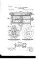
- Figure 1 is a sectional side elevation of the improvement.
- Fig. 2 is a transverse section of the same on the. line 2 2 in Fig. 1.
- Fig. 3 is an end View of the improvement with one of the cylinder-heads removed, and Fig. at is a plan view of the piston-valves.
- the improved steam -engine is provided with a cylinder A, in which reciprocates the hollow piston I3, secured on a piston-rod 0, connected in the usual manner with the main drivin g-shaft of the engine.
- the cylinder'A is provided at or near its ends with the inletports a and I), connected with a common steam-inlet pipe D, connected with the boiler, so that the motive agent can pass through the said pipe D into the ports a and Z), and alternately into the ends of the cylinder A, to exert its force against the heads or ends of the piston B.
- valves E and E respectively, connected with each other by a stem E and arranged .in such a manner that when one valve opens its port the other closes the other port, and vice versa.
- the valve E is connected by a valve-stem 55 with suitable mechanism driven from the main driving-shaft to impart motion to the said valves to alternately connect the respective ports with the ends of the cylinder A.
- cylinder'A is also provided near its middle with exhaust-ports c and 61 leading to branch pipes F and F of the exhaust-pipe F.
- the piston B is made hollow and preferably in the shape shown in Fig. 1, by providing the said piston with two heads B and B se- 65 cured on the piston-rod C and connected with each other by suitable stay-rods, as is plainly shown in Figs. 1 and 2.
- suitable stay-rods as is plainly shown in Figs. 1 and 2.
- In the outer faces of the heads B and B are formed circular seats for ring-shaped valves G and G, re- '70 speetively, connected with each other by longitudinally-extending bars G and G united at or near their middle by a suitable crosshcad G", as is plainly shown in Figs. 2 and 4:.
- Similar inclines G and G are formed on the other bar G and the said inclines GT and G are adapted to be alternately engaged by friction-rollers II and H and the other inclines G and G are adapted to be alternately engaged by friction-rollers II and H
- the friction-rollers II and H are supported on a vertically-extending rod II", and the other friction-rollers II and II are held on a rod H both rods 11 and H being secured in segmental arms Iand I, set in blocks J 0 ing in the cylinder A, to securely hold the 5 said segmental arms in position to prevent lateral motion of the same.
- valves G and G are arranged ports 6 and f, adapted to alternately connect the similar ports 9 and h, respectively, formed in the heads B and B of the piston B.
- the relation of the valves G and G to the valves- E and E is such that when the valve E opens its port a, as shown in Fig. 1, the ports (2 in the valve G do not register with their ports g, while at the same time the valve E closes the port b and the valve G has its port f registering with the port h.
- the steam in front of the piston-head B can pass through the registering ports f and h, between the piston-heads B and B and through the port into the branch pipe F to the exhaust-pipe F.
- a steam-engine comprising a hollow piston connected at all times with the exhaust, and valves mounted to turn 011 the heads or faces of the said piston, to alternately connect the interior of the piston with the ends of the cylinder, substantially as shown and described.
- a steam-engine comprising a cylinder having inlet-ports at the ends of the cylinder and exhaust-ports near the middle thereof, a hollow piston reciprocating in the said cylinder and connected at all times with the said eXhaust-ports, and valves mounted to turn on the heads or faces of the said piston, to alternately connect the interior of the piston with the ends of the cylinder, substantially as shown and described.
- a steam-engine comprising a cylinder having inlet-ports at the ends of the cylinder and exhaust-ports near the middle thereof, a hollow piston reciprocating in the said cylinder and connected at all times with the said exhaust-ports, valves mounted to turn on the heads or faces of the said piston,to alternately connect the interior of the piston with the ends of the cylinder, and means, substantially as described, for automatically turning the said valves on the forward and backward motion of the said piston as set forth.
- a steam-engine comprising a cylinder having inlet-ports at the ends of the cylinder and exhaust-ports near the middle thereof, a hollow piston reciprocating inthe said cylinder and connected at all times with the said exhaust-ports, valves mounted to turn 011 the heads or faces of the said piston,to alternately connect the interior of the piston with the ends of the cylinder, and valves arranged in the said inlet-ports and adapted to alternately open and close the same, substantially as shown and described.
- a steam-engine comprising a cylinder, a piston reciprocating in the said cylinder and having two connected piston-heads having ports, valves mounted to turn over the said piston-head ports, bars connecting the valves with each other and provided with inclines, and friction-rollers held in the said cylinder and adapted to engage the inclines of the said bars to turn the said valves, substantially as shown and described.
Landscapes
- Engineering & Computer Science (AREA)
- Life Sciences & Earth Sciences (AREA)
- Mechanical Engineering (AREA)
- Soil Sciences (AREA)
- Environmental Sciences (AREA)
- General Engineering & Computer Science (AREA)
- Valve-Gear Or Valve Arrangements (AREA)
Description
(No Model.) I
W. P. spa. W. CLEVELAND.
STEAM; ENGINE.
No. 553,747. Patented Jan f zs, 1896.
'lNl/ENTOl-T 4M (1Q) By If WW4) M ATTORNEYS.
"""llllllllluun E-IIIIIII-Z ANDREW BJSRAHMA. FHUTO-UTHQWASNINGTOKEQ I UNITED STATES PATENT OFFICE.
WILLIAM F. CLEVELAND AND EUGENE WV. CLEVELAND, OF ROUNTIIIVAITE, CANADA.
STEAM E'NGIN E.
SPECIFICATION forming part of Letters Patent No. a747, dated January 28, 1896.
Application filed November 17, 1893. Renewed July 2, 1895. Serial No. 554,767. (No model.)
To all whom it may concern.-
Be it known that we,-WILLIAM FITCH CLEVE- LAND and EUGENE WYMAN CLEVELAND, subjects of the Queen of Great Britain, residing at Rounthwaite, in the Province of Manitoba, Dominionof Canada, have invented a new and Improved Steam-Engine, of which the following is a full, clear, and exact description.
The object of the invention is to provide a new and improved steam-engine which is simple and durable in construction, very effective in operation,and arranged to utilize the motive agent to the fullest advantage by providing a full and complete exhaust to prevent back-pressure.
The invention consists principally of a hollow piston connected at all times with the exhaust, and valves on the heads or faces of the said piston to alternately connect the interior of the piston with the ends of the cylinder.
The invention also consists of certain parts and details, and combinations of the same, as will be fully described hereinafter-and then pointed out in the claims.
Reference is to be had to the accompanying drawings, forminga part of this specification, in which similar letters of reference indicate corresponding parts in all the views.
Figure 1 is a sectional side elevation of the improvement. Fig. 2 is a transverse section of the same on the. line 2 2 in Fig. 1. Fig. 3 is an end View of the improvement with one of the cylinder-heads removed, and Fig. at is a plan view of the piston-valves.
The improved steam -engine is provided with a cylinder A, in which reciprocates the hollow piston I3, secured on a piston-rod 0, connected in the usual manner with the main drivin g-shaft of the engine. The cylinder'A is provided at or near its ends with the inletports a and I), connected with a common steam-inlet pipe D, connected with the boiler, so that the motive agent can pass through the said pipe D into the ports a and Z), and alternately into the ends of the cylinder A, to exert its force against the heads or ends of the piston B.
In the ports a and b are arranged the valves E and E", respectively, connected with each other by a stem E and arranged .in such a manner that when one valve opens its port the other closes the other port, and vice versa.
The valve E is connected bya valve-stem 55 with suitable mechanism driven from the main driving-shaft to impart motion to the said valves to alternately connect the respective ports with the ends of the cylinder A. The
cylinder'A is also provided near its middle with exhaust-ports c and 61 leading to branch pipes F and F of the exhaust-pipe F.
The piston B is made hollow and preferably in the shape shown in Fig. 1, by providing the said piston with two heads B and B se- 65 cured on the piston-rod C and connected with each other by suitable stay-rods, as is plainly shown in Figs. 1 and 2. In the outer faces of the heads B and B are formed circular seats for ring-shaped valves G and G, re- '70 speetively, connected with each other by longitudinally-extending bars G and G united at or near their middle by a suitable crosshcad G", as is plainly shown in Figs. 2 and 4:.
On the end of the bar G near the valve G 7 5 and at the inner edge thereof, is formed an incline G and. a similar incline G is formed on the said bar near the valveG and on the outer edge thereof, as'is plainly shown in Fig. 4;. Similar inclines G and G are formed on the other bar G and the said inclines GT and G are adapted to be alternately engaged by friction-rollers II and H and the other inclines G and G are adapted to be alternately engaged by friction-rollers II and H The friction-rollers II and H are supported on a vertically-extending rod II", and the other friction-rollers II and II are held on a rod H both rods 11 and H being secured in segmental arms Iand I, set in blocks J 0 ing in the cylinder A, to securely hold the 5 said segmental arms in position to prevent lateral motion of the same.
In the valves G and G are arranged ports 6 and f, adapted to alternately connect the similar ports 9 and h, respectively, formed in the heads B and B of the piston B. The relation of the valves G and G to the valves- E and E is such that when the valve E opens its port a, as shown in Fig. 1, the ports (2 in the valve G do not register with their ports g, while at the same time the valve E closes the port b and the valve G has its port f registering with the port h. Now, the steam in front of the piston-head B can pass through the registering ports f and h, between the piston-heads B and B and through the port into the branch pipe F to the exhaust-pipe F.
Now, when the several parts are in the position shown in Fig. 1, the live steam enter ing the port a passes through the valve E into the left or outer end of the cylinder A to press against the piston-head B to force the piston to the right in the direction of the arrow a. Steam in front of the head B now exhausts through the registering ports f h and port 0, as above described, and when the piston D nears the end of its inward stroke the friction-rollers H and H act on the inclines G and G so as to cause the valves G and G to turn, whereby the ports h are closed, and the ports 9 are opened by the ports 6 registering with the said ports g. At the time this takes place the valves E and E shift, so that the port a is'closed, and the port 1) opens and live motive agent now passes into the right-hand end of the cylinder A to press on the piston-head B to force the piston in the inverse direction of the arrow d. hen the piston travels in this direction, the steam in front of the head B passes through the registering ports g and 6 between the heads 13 and B to exhaust through the ports 0 (Z to the branch pipe F of the exhaustpipeF leading to the outside. Vhen the pi ston travels in this direction and nears the end of its stroke, the frictionrollers H and H come in contact with the inclines G and G so as to turn the valves G and G to close the ports 9 in the head B and to open the ports h in the head B The above-described operation is then repeatedthat is to say, the valves E and E again shift to the position shown in Fig. 1 and steam now passes to the outer end of the cylinder A to force the piston B in the direction of the arrow at. It will be seen by this arrangement a complete and free exhaust is obtained as soon as the piston nears the end of the cylinder, so that no back-pressure then will be exerted on the piston and the motive agent forcing the piston forward is utilized to the fullest advantage.
Having thus fully described our invention, we claim as new and desire to secure by Letters Patent- 1. A steam-engine, comprising a hollow piston connected at all times with the exhaust, and valves mounted to turn 011 the heads or faces of the said piston, to alternately connect the interior of the piston with the ends of the cylinder, substantially as shown and described.
2. A steam-engine, comprising a cylinder having inlet-ports at the ends of the cylinder and exhaust-ports near the middle thereof, a hollow piston reciprocating in the said cylinder and connected at all times with the said eXhaust-ports, and valves mounted to turn on the heads or faces of the said piston, to alternately connect the interior of the piston with the ends of the cylinder, substantially as shown and described.
3. A steam-engine, comprising a cylinder having inlet-ports at the ends of the cylinder and exhaust-ports near the middle thereof, a hollow piston reciprocating in the said cylinder and connected at all times with the said exhaust-ports, valves mounted to turn on the heads or faces of the said piston,to alternately connect the interior of the piston with the ends of the cylinder, and means, substantially as described, for automatically turning the said valves on the forward and backward motion of the said piston as set forth.
4. A steam-engine, comprising a cylinder having inlet-ports at the ends of the cylinder and exhaust-ports near the middle thereof, a hollow piston reciprocating inthe said cylinder and connected at all times with the said exhaust-ports, valves mounted to turn 011 the heads or faces of the said piston,to alternately connect the interior of the piston with the ends of the cylinder, and valves arranged in the said inlet-ports and adapted to alternately open and close the same, substantially as shown and described.
5. A steam-engine, comprising a cylinder, a piston reciprocating in the said cylinder and having two connected piston-heads having ports, valves mounted to turn over the said piston-head ports, bars connecting the valves with each other and provided with inclines, and friction-rollers held in the said cylinder and adapted to engage the inclines of the said bars to turn the said valves, substantially as shown and described.
WILLIAM F. CLEVELAND. EUGENE XV. CLEVELAND.
Witnesses:
LEVI STOCKTON, WILLIAM CowAN.
Publications (1)
| Publication Number | Publication Date |
|---|---|
| US553747A true US553747A (en) | 1896-01-28 |
Family
ID=2622486
Family Applications (1)
| Application Number | Title | Priority Date | Filing Date |
|---|---|---|---|
| US553747D Expired - Lifetime US553747A (en) | cleveland |
Country Status (1)
| Country | Link |
|---|---|
| US (1) | US553747A (en) |
-
0
- US US553747D patent/US553747A/en not_active Expired - Lifetime
Similar Documents
| Publication | Publication Date | Title |
|---|---|---|
| US746158A (en) | Engine for steam-pumps. | |
| US696691A (en) | Valve for engines. | |
| US358804A (en) | Steam-actuated valve | |
| US431996A (en) | Steam-engine | |
| US1084512A (en) | Multiple-power engine. | |
| US969027A (en) | Compound engine. | |
| US454753A (en) | Steam-actuated valve | |
| US321325A (en) | hodges | |
| US645893A (en) | Steam-engine. | |
| US674706A (en) | Engine. | |
| US463450A (en) | Compound engine | |
| US179713A (en) | Improvement in compound steawi-engines | |
| US1074484A (en) | Valve. | |
| US161451A (en) | Improvement in cut-offs for steam-engines | |
| US551262A (en) | William fitch cleveland and eugene wyman cleveland | |
| US346616A (en) | Steam-engine | |
| US193772A (en) | Helem meebill | |
| US361602A (en) | Steam-engine | |
| US252331A (en) | Locomotive engine | |
| US382309A (en) | Steam engine | |
| USRE5985E (en) | Improvement in steam-engines | |
| US618453A (en) | Rotary reciprocating engine | |
| US321842A (en) | Valveless engine | |
| US825924A (en) | Duplex steam-engine. | |
| US612969A (en) | Steam-engine |