US5528859A - Pressure-fit gate with toggle handle - Google Patents
Pressure-fit gate with toggle handle Download PDFInfo
- Publication number
- US5528859A US5528859A US08/335,353 US33535394A US5528859A US 5528859 A US5528859 A US 5528859A US 33535394 A US33535394 A US 33535394A US 5528859 A US5528859 A US 5528859A
- Authority
- US
- United States
- Prior art keywords
- panel
- lateral movement
- carriage
- relative
- linkage
- Prior art date
- Legal status (The legal status is an assumption and is not a legal conclusion. Google has not performed a legal analysis and makes no representation as to the accuracy of the status listed.)
- Expired - Lifetime
Links
Images


Classifications
-
- E—FIXED CONSTRUCTIONS
- E06—DOORS, WINDOWS, SHUTTERS, OR ROLLER BLINDS IN GENERAL; LADDERS
- E06B—FIXED OR MOVABLE CLOSURES FOR OPENINGS IN BUILDINGS, VEHICLES, FENCES OR LIKE ENCLOSURES IN GENERAL, e.g. DOORS, WINDOWS, BLINDS, GATES
- E06B9/00—Screening or protective devices for wall or similar openings, with or without operating or securing mechanisms; Closures of similar construction
- E06B9/02—Shutters, movable grilles, or other safety closing devices, e.g. against burglary
-
- E—FIXED CONSTRUCTIONS
- E06—DOORS, WINDOWS, SHUTTERS, OR ROLLER BLINDS IN GENERAL; LADDERS
- E06B—FIXED OR MOVABLE CLOSURES FOR OPENINGS IN BUILDINGS, VEHICLES, FENCES OR LIKE ENCLOSURES IN GENERAL, e.g. DOORS, WINDOWS, BLINDS, GATES
- E06B9/00—Screening or protective devices for wall or similar openings, with or without operating or securing mechanisms; Closures of similar construction
- E06B2009/002—Safety guards or gates
Definitions
- the invention relates generally to a barrier such as a safety gate that is removably insertable into an opening such as a doorway.
- a barrier such as a safety gate that is removably insertable into an opening such as a doorway.
- Such gates are used, for example, to prevent an infant, a child or a pet from passing through the doorway.
- the invention relates to an adjustable width, pressure-fit gate that is frictionally retained in the doorway opening by application of outward lateral force to the sides of the opening.
- This invention is an improvement over the type of gate disclosed in the U.S. patent application of Carl M. Stern being filed on even date and entitled PRESSURE FIT GATE.
- a first panel member is coupled to a partially overlapping second panel member so that the panels are slidable laterally relative to each other, thus changing the overall width of the gate.
- a carriage member is slidably mounted on the second panel for lateral movement relative to the second panel and a displacing mechanism is coupled with the carriage member and the second panel and is selectively operable to laterally displace the carriage relative to the second panel.
- An engagement mechanism is connected to the carriage for selectively engaging with and nonengaging with the first panel.
- the expansion mechanism may include an over-center linkage.
- the present invention provides a gate having a first panel member coupled to a partially overlapping second panel member so that the panels are slidable laterally relative to each other, thus changing the overall width of the gate.
- An over-center type toggle linkage has a pivot link and a handle link and is operable to laterally expand and contract the lateral distance between the ends.
- One end of the pivot link is pivotally connected to the first panel and the other end is connected to a medial portion of the handle link.
- One end of the handle link is pivotally connected to a sliding carriage that slides relative to the second panel and the carriage and handle link end are selectively engagable with the second panel by a releasable engagement mechanism.
- the engagement mechanism is disengaged, the panels are free to slide laterally to change the width of the gate.
- operation of the toggle linkage expands or contracts the overall width of the gate.
- the engagement mechanism comprises a slider coupled to a locking knob by a threaded coupling with the knob being located proximate to the pivot axis of the handle link and the carriage.
- FIG. 1A is a front elevation view of a preferred embodiment of the gate of the present invention.
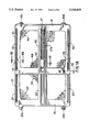
- FIG. 1B is a rear elevation view of the gate in an unexpanded position.
- FIG. 2 is an exploded view of the gate.
- FIG. 3A is a partial rear elevation view showing the linkage in the expanded position.
- FIG. 3B is a partial rear elevation view showing the linkage in the unexpanded position.
- FIG. 3C is partial rear elevation view of an alternative embodiment of the invention.
- FIGS. 4A, 4B and 4C are partial cross sectional views taken along the lines indicated in FIG. 1A.
- FIGS. 5A and 5B are perspective views of the locking knob.
- FIGS. 6A, 6B, and 6C are perspective views of the carriage.
- FIGS. 7A and 7B are perspective views of the handle link.
- FIGS. 8A and 8B are perspective views of the pivot link.
- FIGS. 9A, 9B, 9C, and 9D are perspective views of the locking slider.
- FIGS. 10A and 10B are perspective views of the front sliders.
- FIGS. 11A and 11B are perspective views of the rear sliders.
- the apparatus generally includes a rear panel 20 that is coupled to a partially overlapping front panel 40 so that the panels are slidable laterally relative to each other, thus changing the overall width of the gate.
- An overcenter type toggle linkage 60 has two links and is operable via a handle portion of one of the links to laterally expand and contract the lateral distance between the distal ends of the links.
- One end of the toggle linkage 60 is connected to the rear panel 20, and the other end of the toggle linkage 60 is selectively engagable with the front panel 40 by a releasable engagement mechanism 70.
- the engagement mechanism 70 is disengaged or released to permit adjustment of the overall unexpanded width of the gate.
- the engagement mechanism 70 is released, the panels 20 and 40 remain freely slidable relative to each other, and permit a range of adjustment of the overall width of the gate apparatus.
- the toggle linkage 60 When the engagement mechanism 70 is engaged, the toggle linkage 60 is operable to displace the rear panel 20 and front panel 40 relative to each other by a predetermined distance to expand the gate and apply an outward lateral force to the sides of an opening to frictionally retain the gate in the opening. This is accomplished because when the engagement mechanism 70 is engaged with the front panel 40, expanding the toggle linkage 60 will laterally displace the panels 20 and 40 relative to each other, thereby expanding the overall gate width. Conversely, contracting the toggle linkage 60 will displace the panels 20 and 40 relative to each other to reduce the overall gate width.
- the rear panel 20 is slidably coupled to the front panel 40 by a pair of rear sliders 45, 46 attached to the front panel 40 that pass through and slide along slots 22, 23 in the rear panel 20.
- a pair of front sliders 25, 26 attached to the rear panel 20 slide in slots 42, 43 in the front panel 40.
- This slider and slot arrangement provides for a wide range of lateral movement of the gate panels 20 and 40 relative to each other to facilitate adjustment of the unexpanded (and hence also the expanded) width of the gate.
- the rear panel 20 is provided with upper and lower bumpers 29a and 29b which have a rubber or other suitable gripping surface for contacting the side of the opening to be blocked.
- the front panel 40 includes upper and lower bumpers 49a and 49b. One or more of these bumpers may be horizontally adjustable to accommodate out-of-square or uneven openings.
- the front panel 40 includes a generally rectangular perimeter frame 41 and a center ridge 48. Mesh panels 44 are provided as shown within the perimeter frame 41.
- the rear panel 20 includes a frame 21 similar to that of the front panel 40 including a center ridge 28 and mesh panels 24. It will be appreciated that the panels 20 and 40 may take any of the many known panel forms such as those suitable for use in security gates used with infants, children or pets.
- the gate panels may be each comprise integral plastic molded panels as shown, or alternatively the gate panels may each comprise a rectangular wood perimeter frame with a wire or plastic grid material inside the frame.
- the engagement mechanism locking slider 71 is attached by a threaded rod 72 to a locking knob 73.
- the rod 72 passes through a center slot 47 in the front panel 40 and a center slot 27 in the rear panel 20, and also passes through a carriage 61.
- the threaded rod 72 and slider 71 are capable of sliding along the slot 47 when the knob 73 is loosened. However, when the knob 73 is tightened, the slider 71 is urged against the front edges of the slot 47 and contacts and frictionally engages the front panel 40.
- the inner side of the slider 71 has teeth 71a that mate with teeth 47a on the edges of the slot 47 when the locking knob 73 is tightened.
- the slider 71 may have a decorative cover 71b mounted to this outer side to improve its appearance.
- the carriage 61 is slidably mounted for lateral motion relative to the rear panel 20 along the slot 27 via a portion 61b that fits slidably in the slot 27 and is capable of such sliding even when the knob 73 is tightened.
- the over-center linkage 60 includes a handle link 62 and a pivot link 63.
- the handle link 62 is pivotally coupled at one end to the carriage 61 as follows--the handle link 62 has a circular indentation 62a on its rear surface into which fits a mating circular projection 61a on the front of the carriage 61 so as to permit the handle link 62 to rotate about the axis of the edges (which is also the axis of the rod 72) relative to the carriage 61.
- the range of rotation of the handle link 62 about the that axis relative to the carriage 61 is limited at the fully raised position (shown in FIG. 3B) by contact between an edge 62d on the handle link 62 and an edge of 63b on the pivot link 63.
- the range of rotation at the fully depressed position is limited by contact between an edge 62c on the handle link 62 and an edge 63c the pivot link 63.
- the handle link 62 at a medial portion thereof is pivotally connected to the end of pivot link 63 by a pin 65.
- a base link member 69 is fixedly mounted to rear gate panel 20, and the end of the pivot link 63 away from the handle link 62 is pivotally connected to the rear panel 20 via the base link 69 by a pin 64.
- the handle link 62 may feature a hand grip indentation 62b to facilitate lifting the handle link 62.
- Lifting on the handle link 62 raises the free end 62e of the handle link 62 and thus rotates the handle link 62 and the pivot link 63 upwards into the position shown in FIG. 3B, and accordingly the over-center linkage 60 is foreshortened laterally--that is the lateral distance between the pin 64 and the pivot axis of the handle link 62 about the carriage 61 (i.e. the threaded rod 72) is reduced.
- a spring 81 or other resilient member is provided to permit some lateral travel of the link 63 relative to the rear panel 20.
- the pin 64 may be mounted for some lateral travel relative to the base link 69, and the spring 81 may be connected to the pin 64 and the link 69 to sere two functions.
- the spring 81 will absorb some or all of the compressive forces created when the gate is expanded, and will also consequently limit the maximum outward force that the gate will apply.
- the spring 81 will bias the linkage 60 towards the unexpanded position shown in FIG. 3B.
- the spring may alternatively be positioned between the base link 69 and the gate panel 20 with the base link 69 being mounted for lateral movement relative to the rear panel 20.
- the operation of the gate is as follows. Initially, the user places the gate within the opening to be blocked, the rear side facing away from where the child or pet will be enclosed. With the knob 73 loosened and the handle link 62 fully raised, the panels 20 and 40 are slidably width adjusted so that the width of the gate is equal to or very slightly less than the width of the opening. Next, the knob 73 is fully tightened to set the unexpanded width of the gate. This unexpanded width will remain set the same until the knob 73 is loosened and accordingly can remain the same over several installation and removal procedures of the gate.
- the gate is then inserted into the opening and the handle link 62 is fully depressed, thus expanding the toggle linkage 60 so that the carriage 61 is displaced laterally outwardly relative to the rear panel 20. Since the slider 71 is in engagement with the front panel 40, the front panel 40 is displaced laterally outward relative to the rear panel 20 by a predetermined amount.
- the links 62 and 63 rotate slightly over-center after the gate is completely expanded so that it is contracted by a slight amount. That is, the pin 65 (the pivot axis of the connection of links 62 and 63 to each other) is located below a line connecting the threaded rod 72 (the pivot axis of the handle link 62 and the carriage 61) and the pin 64 (the pivot axis of the connections of the pivot link 63 to the rear panel 20 via the base link 69). Due to this over-center rotation, the compressive forces on the gate once installed urge the linkage 60 into the locked position--resulting in an upward pressure being required on the handle link 62 to release the gate, thereby reducing the chances of accidental release of the gate. The amount of over-center travel is limited by contact between the edge 62c of the link 62 and an edge 63c of the link 63.
- the gate is released by raising the handle link 62, which pulls upward on the center pivot connection 65 of the links 62 and 63 and accordingly also moves the rear panel 20 and the front panel 40 toward each other and releases the pressure on the gate. This permits the gate to be removed from the opening. If the locking knob 73 is not loosened, the gate will be ready for re-insertion into the same opening. If it is desired to use the gate in a different opening, the locking knob 73 is loosened, and the overall width adjustment process is begun as described above.
- the mesh panels have elongated holes oriented in the angled directions shown so that the shear stress of the gate caused by outward lateral force acting at the center ridge and the inward lateral forces acting on the bumpers is distributed as tension along the lines of the axes of the slot rather than compression, which orientation helps avoid buckling of the mesh panels.
- the gate design described above is advantageous in at least two respects.
- the part of the handle link 62 (the handle grip portion 62b) operated by the user is integral with the handle link 62 itself.
- the locking knob 73 is located inset into the carriage end of the handle link 62 at the pivot axis of the handle link and the carriage (i.e. the axis of the threaded rod 72), the knob 73 is very conveniently located near the handle grip 62b for ease of use.
- the location of the locking knob 73 in the handle link 62 also helps make the toggle mechanism and engagement mechanism combination laterally compact, and in particular makes the carriage member more compact, thereby realizing a reduction in the potential for buckling or bending of the carriage member.
Abstract
A gate has a first panel member coupled to a partially overlapping second panel member so that the panels are slidable laterally relative to each other, thus changing the overall width of the gate. An over-center type toggle linkage has a pivot link and a handle link and is operable to laterally expand and contract the lateral distance between the ends. One end of the pivot link is pivotally connected to the first panel and the other end is connected to a medial portion of the handle link. One end of the handle link is pivotally connected to a sliding carriage that slides relative to the second panel and the carriage and handle link end are selectively engagable with the second panel by a releasable engagement mechanism. When the engagement mechanism is disengaged, the panels are free to slide laterally to change the width of the gate. When the engagement mechanism is engaged, operation of the toggle linkage expands or contracts the overall width of the gate. The engagement mechanism may include a slider coupled to a locking knob by a threaded coupling with the knob being located proximate to the pivot axis of the handle link and the carriage.
Description
The invention relates generally to a barrier such as a safety gate that is removably insertable into an opening such as a doorway. Such gates are used, for example, to prevent an infant, a child or a pet from passing through the doorway. More specifically, the invention relates to an adjustable width, pressure-fit gate that is frictionally retained in the doorway opening by application of outward lateral force to the sides of the opening.
This invention is an improvement over the type of gate disclosed in the U.S. patent application of Carl M. Stern being filed on even date and entitled PRESSURE FIT GATE. In the type of gate disclosed in that application, a first panel member is coupled to a partially overlapping second panel member so that the panels are slidable laterally relative to each other, thus changing the overall width of the gate. A carriage member is slidably mounted on the second panel for lateral movement relative to the second panel and a displacing mechanism is coupled with the carriage member and the second panel and is selectively operable to laterally displace the carriage relative to the second panel. An engagement mechanism is connected to the carriage for selectively engaging with and nonengaging with the first panel. When the engaging mechanism is non-engaged lateral movement of the carriage member with respect to the second panel does not cause relative lateral movement between the first panel and the second panel, and when the engaging mechanism is engaged lateral movement of the carriage member causes corresponding relative lateral movement between the first panel and the second panel. The expansion mechanism may include an over-center linkage.
In one aspect, the present invention provides a gate having a first panel member coupled to a partially overlapping second panel member so that the panels are slidable laterally relative to each other, thus changing the overall width of the gate. An over-center type toggle linkage has a pivot link and a handle link and is operable to laterally expand and contract the lateral distance between the ends. One end of the pivot link is pivotally connected to the first panel and the other end is connected to a medial portion of the handle link. One end of the handle link is pivotally connected to a sliding carriage that slides relative to the second panel and the carriage and handle link end are selectively engagable with the second panel by a releasable engagement mechanism. When the engagement mechanism is disengaged, the panels are free to slide laterally to change the width of the gate. When the engagement mechanism is engaged, operation of the toggle linkage expands or contracts the overall width of the gate.
In another aspect of the invention, the engagement mechanism comprises a slider coupled to a locking knob by a threaded coupling with the knob being located proximate to the pivot axis of the handle link and the carriage.
FIG. 1A is a front elevation view of a preferred embodiment of the gate of the present invention.
FIG. 1B is a rear elevation view of the gate in an unexpanded position.
FIG. 2 is an exploded view of the gate.
FIG. 3A is a partial rear elevation view showing the linkage in the expanded position.
FIG. 3B is a partial rear elevation view showing the linkage in the unexpanded position.
FIG. 3C is partial rear elevation view of an alternative embodiment of the invention.
FIGS. 4A, 4B and 4C are partial cross sectional views taken along the lines indicated in FIG. 1A.
FIGS. 5A and 5B are perspective views of the locking knob.
FIGS. 6A, 6B, and 6C are perspective views of the carriage.
FIGS. 7A and 7B are perspective views of the handle link.
FIGS. 8A and 8B are perspective views of the pivot link.
FIGS. 9A, 9B, 9C, and 9D are perspective views of the locking slider.
FIGS. 10A and 10B are perspective views of the front sliders.
FIGS. 11A and 11B are perspective views of the rear sliders.
Reference will now be made in detail to presently preferred embodiments of the invention, examples of which are illustrated in the accompanying drawings. As depicted in FIGS. 1 through 5, the apparatus generally includes a rear panel 20 that is coupled to a partially overlapping front panel 40 so that the panels are slidable laterally relative to each other, thus changing the overall width of the gate. An overcenter type toggle linkage 60 has two links and is operable via a handle portion of one of the links to laterally expand and contract the lateral distance between the distal ends of the links. One end of the toggle linkage 60 is connected to the rear panel 20, and the other end of the toggle linkage 60 is selectively engagable with the front panel 40 by a releasable engagement mechanism 70.
The engagement mechanism 70 is disengaged or released to permit adjustment of the overall unexpanded width of the gate. When the engagement mechanism 70 is released, the panels 20 and 40 remain freely slidable relative to each other, and permit a range of adjustment of the overall width of the gate apparatus.
When the engagement mechanism 70 is engaged, the toggle linkage 60 is operable to displace the rear panel 20 and front panel 40 relative to each other by a predetermined distance to expand the gate and apply an outward lateral force to the sides of an opening to frictionally retain the gate in the opening. This is accomplished because when the engagement mechanism 70 is engaged with the front panel 40, expanding the toggle linkage 60 will laterally displace the panels 20 and 40 relative to each other, thereby expanding the overall gate width. Conversely, contracting the toggle linkage 60 will displace the panels 20 and 40 relative to each other to reduce the overall gate width.
The preferred embodiment is described in more detail below. The rear panel 20 is slidably coupled to the front panel 40 by a pair of rear sliders 45, 46 attached to the front panel 40 that pass through and slide along slots 22, 23 in the rear panel 20. Similarly, a pair of front sliders 25, 26 attached to the rear panel 20 slide in slots 42, 43 in the front panel 40. This slider and slot arrangement provides for a wide range of lateral movement of the gate panels 20 and 40 relative to each other to facilitate adjustment of the unexpanded (and hence also the expanded) width of the gate. The rear panel 20 is provided with upper and lower bumpers 29a and 29b which have a rubber or other suitable gripping surface for contacting the side of the opening to be blocked. Similarly, the front panel 40 includes upper and lower bumpers 49a and 49b. One or more of these bumpers may be horizontally adjustable to accommodate out-of-square or uneven openings.
The front panel 40 includes a generally rectangular perimeter frame 41 and a center ridge 48. Mesh panels 44 are provided as shown within the perimeter frame 41. The rear panel 20 includes a frame 21 similar to that of the front panel 40 including a center ridge 28 and mesh panels 24. It will be appreciated that the panels 20 and 40 may take any of the many known panel forms such as those suitable for use in security gates used with infants, children or pets. By way of example only, the gate panels may be each comprise integral plastic molded panels as shown, or alternatively the gate panels may each comprise a rectangular wood perimeter frame with a wire or plastic grid material inside the frame.
The engagement mechanism locking slider 71 is attached by a threaded rod 72 to a locking knob 73. The rod 72 passes through a center slot 47 in the front panel 40 and a center slot 27 in the rear panel 20, and also passes through a carriage 61. The threaded rod 72 and slider 71 are capable of sliding along the slot 47 when the knob 73 is loosened. However, when the knob 73 is tightened, the slider 71 is urged against the front edges of the slot 47 and contacts and frictionally engages the front panel 40. The inner side of the slider 71 has teeth 71a that mate with teeth 47a on the edges of the slot 47 when the locking knob 73 is tightened. Thus, when the knob 73 is loosened, the panels 20 and 40 are free to slide relative each other, and when the knob 73 is tightened, the slider 71, rod 72, knob 73 and carriage 61 are fixed relative to the front panel 40. As shown in FIGS. 9A through 9D, the slider 71 may have a decorative cover 71b mounted to this outer side to improve its appearance.
Referring particularly to FIGS. 2, 3A, 3B, the carriage 61 is slidably mounted for lateral motion relative to the rear panel 20 along the slot 27 via a portion 61b that fits slidably in the slot 27 and is capable of such sliding even when the knob 73 is tightened. The over-center linkage 60 includes a handle link 62 and a pivot link 63. The handle link 62 is pivotally coupled at one end to the carriage 61 as follows--the handle link 62 has a circular indentation 62a on its rear surface into which fits a mating circular projection 61a on the front of the carriage 61 so as to permit the handle link 62 to rotate about the axis of the edges (which is also the axis of the rod 72) relative to the carriage 61. The range of rotation of the handle link 62 about the that axis relative to the carriage 61 is limited at the fully raised position (shown in FIG. 3B) by contact between an edge 62d on the handle link 62 and an edge of 63b on the pivot link 63. The range of rotation at the fully depressed position (shown in FIG. 3A) is limited by contact between an edge 62c on the handle link 62 and an edge 63c the pivot link 63.
The handle link 62 at a medial portion thereof is pivotally connected to the end of pivot link 63 by a pin 65. A base link member 69 is fixedly mounted to rear gate panel 20, and the end of the pivot link 63 away from the handle link 62 is pivotally connected to the rear panel 20 via the base link 69 by a pin 64. The handle link 62 may feature a hand grip indentation 62b to facilitate lifting the handle link 62. Lifting on the handle link 62 raises the free end 62e of the handle link 62 and thus rotates the handle link 62 and the pivot link 63 upwards into the position shown in FIG. 3B, and accordingly the over-center linkage 60 is foreshortened laterally--that is the lateral distance between the pin 64 and the pivot axis of the handle link 62 about the carriage 61 (i.e. the threaded rod 72) is reduced.
Since the pivot link 63 is effectively attached to the rear panel 20 by the pin 64 and the base link 69, this lateral foreshortening of the over-center linkage 60 moves the carriage 61 laterally inward toward the linkage 60. If the knob 73 is not tightened, the front panel 40 is not affected and remains free to slide laterally relative to the rear panel 20. However, if the handle link 62 is raised while the knob 73 is tightened, the front panel 40 will be moved inward laterally relative to the rear panel 20 by a distance corresponding to the inward lateral movement of the carriage 61 into the configuration shown in FIG. 3B. Then, depressing the handle link 62 causes the front panel 40 to move outward laterally relative the rear panel 20 into the configuration shown in FIG. 3A.
In an alternative embodiment shown schematically in FIG. 3C, a spring 81 or other resilient member is provided to permit some lateral travel of the link 63 relative to the rear panel 20. As illustrated schematically in FIG. 3C, the pin 64 may be mounted for some lateral travel relative to the base link 69, and the spring 81 may be connected to the pin 64 and the link 69 to sere two functions. First, the spring 81 will absorb some or all of the compressive forces created when the gate is expanded, and will also consequently limit the maximum outward force that the gate will apply. Second, the spring 81 will bias the linkage 60 towards the unexpanded position shown in FIG. 3B. The spring may alternatively be positioned between the base link 69 and the gate panel 20 with the base link 69 being mounted for lateral movement relative to the rear panel 20.
The operation of the gate is as follows. Initially, the user places the gate within the opening to be blocked, the rear side facing away from where the child or pet will be enclosed. With the knob 73 loosened and the handle link 62 fully raised, the panels 20 and 40 are slidably width adjusted so that the width of the gate is equal to or very slightly less than the width of the opening. Next, the knob 73 is fully tightened to set the unexpanded width of the gate. This unexpanded width will remain set the same until the knob 73 is loosened and accordingly can remain the same over several installation and removal procedures of the gate.
The gate is then inserted into the opening and the handle link 62 is fully depressed, thus expanding the toggle linkage 60 so that the carriage 61 is displaced laterally outwardly relative to the rear panel 20. Since the slider 71 is in engagement with the front panel 40, the front panel 40 is displaced laterally outward relative to the rear panel 20 by a predetermined amount.
As shown in FIG. 3A, the links 62 and 63 rotate slightly over-center after the gate is completely expanded so that it is contracted by a slight amount. That is, the pin 65 (the pivot axis of the connection of links 62 and 63 to each other) is located below a line connecting the threaded rod 72 (the pivot axis of the handle link 62 and the carriage 61) and the pin 64 (the pivot axis of the connections of the pivot link 63 to the rear panel 20 via the base link 69). Due to this over-center rotation, the compressive forces on the gate once installed urge the linkage 60 into the locked position--resulting in an upward pressure being required on the handle link 62 to release the gate, thereby reducing the chances of accidental release of the gate. The amount of over-center travel is limited by contact between the edge 62c of the link 62 and an edge 63c of the link 63.
When the gate has been expanded inside the opening as described above, it applies an outward lateral force against the sides of the opening. These forces are taken up resiliently in part by compression of the bumpers 29a, 29b, 49a and 49b, and in part by compression and/or minor deflection of the panels 20 and 40.
The gate is released by raising the handle link 62, which pulls upward on the center pivot connection 65 of the links 62 and 63 and accordingly also moves the rear panel 20 and the front panel 40 toward each other and releases the pressure on the gate. This permits the gate to be removed from the opening. If the locking knob 73 is not loosened, the gate will be ready for re-insertion into the same opening. If it is desired to use the gate in a different opening, the locking knob 73 is loosened, and the overall width adjustment process is begun as described above.
The mesh panels have elongated holes oriented in the angled directions shown so that the shear stress of the gate caused by outward lateral force acting at the center ridge and the inward lateral forces acting on the bumpers is distributed as tension along the lines of the axes of the slot rather than compression, which orientation helps avoid buckling of the mesh panels.
The gate design described above is advantageous in at least two respects. First, the part of the handle link 62 (the handle grip portion 62b) operated by the user is integral with the handle link 62 itself. Second, since the locking knob 73 is located inset into the carriage end of the handle link 62 at the pivot axis of the handle link and the carriage (i.e. the axis of the threaded rod 72), the knob 73 is very conveniently located near the handle grip 62b for ease of use. The location of the locking knob 73 in the handle link 62 also helps make the toggle mechanism and engagement mechanism combination laterally compact, and in particular makes the carriage member more compact, thereby realizing a reduction in the potential for buckling or bending of the carriage member.
Although the preferred embodiment has been described above in the context of a gate for blocking a doorway opening, it will be readily appreciated that other applications are possible for the invention. For example, the combination of an over-center linkage having a handle link and a sliding carriage, and/or the combination of an engaging mechanism located on the axis of the pivot axis of the handle link, may be employed with suitable modifications for blocking any opening having side frames such as, for example, a window.
Claims (5)
1. A pressure-fit barrier for blocking an opening, comprising:
a first panel;
a second panel slidably coupled to said first panel for lateral movement relative thereto;
a linkage having a first handle link having a first end, a second handle end, and a medial portion located between said first and second ends, and a second link having a third end and a fourth end, said third end being pivotally attached to said medial portion, and said linkage being selectively operable between an expanded position in which said first and fourth ends are separated by a first distance and a contracted position in which said first and fourth ends are separated by a second distance less than the first distance, and said fourth end of said linkage being pivotally connected to said second panel;
a carriage member slidably mounted on said second panel for lateral movement relative to said second panel, said first end of said handle link being pivotally coupled to said carriage, wherein operation of said linkage between the contracted position and the expanded position causes lateral movement of said carriage relative to said second panel; and
engaging means connected to said carriage and selectively engagable and non-engagable with said first panel, wherein when said engaging means is non-engaged lateral movement of said carriage member does not cause relative lateral movement between said first panel and said second panel, and when said engaging means is engaged lateral movement of said carriage member causes corresponding relative lateral movement between said first panel and said second panel.
2. A pressure-fit barrier for blocking an opening, comprising:
a first panel;
a second panel slidably coupled to said first panel for lateral movement relative thereto;
a base member coupled to said first panel for slidable motion relative thereto;
means for biasing said base member laterally relative to said second panel;
a linkage having a first handle link having a first end, a second handle end, and a medial portion located between said first and second ends, and a second link having a third end and a fourth end, said third end being pivotally attached to said medial portion, and said linkage being selectively operable between an expanded position in which said first and fourth ends are separated by a first distance and a contracted position in which said first and fourth ends are separated by a second distance less than the first distance, and said fourth end of said linkage being pivotally connected to said base member;
a carriage member slidably mounted on said second panel for lateral movement relative to said second panel, said first end of said handle link being pivotally coupled to said carriage, wherein operation of said linkage between the contracted position and the expanded position causes lateral movement of said carriage relative to said second panel; and
engaging means connected to said carriage and selectively engagable and non-engagable with said first panel, wherein when said engaging means is non-engaged lateral movement of said carriage member does not cause relative lateral movement between said first panel and said second panel, and when said engaging means is engaged lateral movement of said carriage member causes corresponding relative lateral movement between said first panel and said second panel.
3. A pressure-fit barrier for blocking an opening, comprising:
a first panel;
a second panel slidably coupled to said first panel for lateral movement relative thereto;
a linkage having first and second ends and selectively operable between an expanded position in which said ends are separated by a first distance and a contracted position in which said ends are separated by a second distance less than the first distance, said fourth end of said linkage being pivotally connected to said second panel;
a carriage member slidably mounted on said second panel for lateral movement relative to said second panel, said first end of said handle link being pivotally coupled to said carriage for rotation about a first axis, wherein operation of said linkage between the contracted position and the expanded position causes lateral movement of said carriage relative to said second panel; and
engaging means connected to said carriage and selectively engagable and non-engagable with said first panel, said engaging mechanism comprising:
a slider for selectively frictionally engaging said second panel; and
a knob having a threaded coupling for coupling said knob to said slider; said knob being located substantially concentric about said first axis, wherein said knob is rotatable to cause said slider to engage said second panel;
wherein when said engaging means is non-engaged lateral movement of said carriage member does not cause relative lateral movement between said first panel and said second panel, and when said engaging means is engaged lateral movement of said carriage member causes corresponding relative lateral movement between said first panel and said second panel.
4. A pressure-fit barrier for blocking an opening, comprising:
a first panel;
a second panel slidably coupled to said first panel for lateral movement relative thereto;
a linkage having a first handle link having a first end, a medial portion, and a second end, and a second link having a third end and a fourth end, said third end being pivotally attached to said medial portion, and said linkage being selectively operable between an expanded position in which said first and fourth ends are separated by a first distance and a contracted position in which said first and fourth ends are separated by a second distance less than the first distance, and said fourth end of said linkage being pivotally connected to said second panel;
a carriage member slidably mounted on said second panel for lateral movement relative to said second panel, said first end of said handle link being pivotally coupled to said carriage, wherein operation of said linkage between the contracted position and the expanded position causes lateral movement of said carriage relative to said second panel; and
engaging means connected to said carriage and selectively engagable and non-engagable with said first panel, said engaging means comprising:
a slider for selectively frictionally engaging said second panel; and
a knob having a threaded coupling for coupling said knob to said slider; said knob being located substantially concentric about said first axis, wherein said knob is rotatable to cause said slider to engage said second panel;
wherein when said engaging means is non-engaged, lateral movement of said carriage member does not cause relative lateral movement between said first panel and said second panel, and when said engaging means is engaged, lateral movement of said carriage member causes corresponding relative lateral movement between said first panel and said second panel.
5. A pressure-fit barrier for blocking an opening according to claim 4, wherein said second panel has a row of first teeth and said slider has a contact surface defining a row of second teeth that are engagable with said first teeth.
Priority Applications (1)
| Application Number | Priority Date | Filing Date | Title |
|---|---|---|---|
| US08/335,353 US5528859A (en) | 1994-11-03 | 1994-11-03 | Pressure-fit gate with toggle handle |
Applications Claiming Priority (1)
| Application Number | Priority Date | Filing Date | Title |
|---|---|---|---|
| US08/335,353 US5528859A (en) | 1994-11-03 | 1994-11-03 | Pressure-fit gate with toggle handle |
Publications (1)
| Publication Number | Publication Date |
|---|---|
| US5528859A true US5528859A (en) | 1996-06-25 |
Family
ID=23311420
Family Applications (1)
| Application Number | Title | Priority Date | Filing Date |
|---|---|---|---|
| US08/335,353 Expired - Lifetime US5528859A (en) | 1994-11-03 | 1994-11-03 | Pressure-fit gate with toggle handle |
Country Status (1)
| Country | Link |
|---|---|
| US (1) | US5528859A (en) |
Cited By (24)
| Publication number | Priority date | Publication date | Assignee | Title |
|---|---|---|---|---|
| GB2317636A (en) * | 1996-09-04 | 1998-04-01 | Norman William Lainchbury | Removable window security grille |
| US5782039A (en) | 1996-07-17 | 1998-07-21 | Brk Brands, Inc. | Portable gate |
| US5829505A (en) * | 1996-10-30 | 1998-11-03 | Safety 1St, Incorporated | Safety gate |
| US5906068A (en) * | 1996-12-23 | 1999-05-25 | Bode; Gerd | Adjustable child safety gate |
| US5918422A (en) * | 1997-05-14 | 1999-07-06 | Bucher, Jr.; Robert Joseph | Open office panel system |
| US5924242A (en) * | 1996-10-28 | 1999-07-20 | Safety 1St, Inc. | Safety gate |
| US6449901B1 (en) | 2000-06-05 | 2002-09-17 | Safety 1St, Inc. | Security gate |
| US6681523B1 (en) | 1999-10-22 | 2004-01-27 | North States Industries, Inc. | Security gate |
| US20060059779A1 (en) * | 2004-09-21 | 2006-03-23 | Todd Ventrola | Expandable gate |
| US20060156966A1 (en) * | 2004-11-16 | 2006-07-20 | Stilson Daniel W | Confined space barrier |
| US20070271852A1 (en) * | 2006-05-25 | 2007-11-29 | Vaughn Andre B | Entranceway Barrier Apparatus |
| WO2008027304A2 (en) * | 2006-08-25 | 2008-03-06 | Erika Trujillo | Sliding door gat |
| US20080191497A1 (en) * | 2007-02-14 | 2008-08-14 | Mayo Stephen K | Gate latch |
| US20080256865A1 (en) * | 2006-08-25 | 2008-10-23 | James Trujillo | Safety Gate |
| US20090071074A1 (en) * | 2007-07-12 | 2009-03-19 | Lindam Limited | Gate assembly |
| US20120233922A1 (en) * | 2011-03-15 | 2012-09-20 | Carlson Pet Products, Inc. | Barrier with panels sliding parallel |
| US20120324796A1 (en) * | 2011-06-23 | 2012-12-27 | Tsung-Hsiang Wang | Safety gate |
| US8720958B2 (en) | 2011-03-15 | 2014-05-13 | Carlson Pet Products, Inc. | Barrier with panels sliding parallel |
| US20140373448A1 (en) * | 2013-06-24 | 2014-12-25 | Summer Infant (Usa), Inc. | Safety Gate Assembly |
| US9260910B1 (en) | 2012-06-13 | 2016-02-16 | Carlson Pet Products, Inc. | Free standing sliding panel footed barrier |
| US10107030B2 (en) | 2016-01-27 | 2018-10-23 | Dorel Juvenile Group, Inc. | Security gate |
| US10161181B1 (en) * | 2013-08-20 | 2018-12-25 | Carlson Pet Products, Inc. | Expandable barrier with matching panels and corner pet door |
| US10219623B1 (en) * | 2017-09-07 | 2019-03-05 | Helen Of Troy Limited | Expanding drawer divider |
| US10907382B2 (en) | 2016-11-29 | 2021-02-02 | Dorel Juvenile Group, Inc. | Security gate with latch release |
Citations (25)
| Publication number | Priority date | Publication date | Assignee | Title |
|---|---|---|---|---|
| US903564A (en) * | 1908-06-19 | 1908-11-10 | Jacob Wysong | Portable-gate. |
| US1683204A (en) * | 1926-10-12 | 1928-09-04 | Edgar T Mills | Fly screen |
| US2262800A (en) * | 1940-02-19 | 1941-11-18 | John F Farmer | Center adjustable grille |
| US2559066A (en) * | 1949-10-12 | 1951-07-03 | William A Diefenbronn | Adjustable gate |
| US2577034A (en) * | 1949-04-16 | 1951-12-04 | John H Quinlan | Doorway gate |
| US2581857A (en) * | 1948-03-29 | 1952-01-08 | Bertram M Harrison | Removable gate |
| CA494852A (en) * | 1953-07-28 | Hopkins And Buckland Limited | Gates or the like | |
| US2851746A (en) * | 1953-11-30 | 1958-09-16 | Mcphaden Lawrence | Portable gate |
| US2896277A (en) * | 1956-07-30 | 1959-07-28 | Joseph C Halligan | Gate structure |
| US2928146A (en) * | 1958-05-07 | 1960-03-15 | Travers Welding Co Inc | Removable door gate |
| US2982353A (en) * | 1959-07-08 | 1961-05-02 | Kenneth E Luger | Gate structure for temporary closure for passageways |
| US3163205A (en) * | 1962-06-07 | 1964-12-29 | Gottlieb Robert | Adjustable gate |
| US3431966A (en) * | 1967-05-19 | 1969-03-11 | Worldsbest Ind Inc | Friction-held removable gate |
| US3489201A (en) * | 1968-09-13 | 1970-01-13 | Duncan Curry | Portable gate |
| US3680260A (en) * | 1969-05-09 | 1972-08-01 | Helmuth Bauer | Frames lockable between stationary supports |
| US3756469A (en) * | 1970-11-10 | 1973-09-04 | Bulk Liner Corp | Convertible hopper vehicle |
| US4149342A (en) * | 1978-02-13 | 1979-04-17 | Bowers William O | Window guard |
| US4492263A (en) * | 1981-07-13 | 1985-01-08 | Gerico, Inc. | Infant security door gate assembly |
| US4607455A (en) * | 1984-10-01 | 1986-08-26 | North States Industries, Inc. | Adjustable gate for doorways |
| US4787174A (en) * | 1987-06-05 | 1988-11-29 | Tyrone Brown | Child safety gate |
| US4846246A (en) * | 1987-09-23 | 1989-07-11 | Innova Development Corporation | Security gate operable with one hand |
| US4944117A (en) * | 1988-08-30 | 1990-07-31 | Gerico, Inc. | Foothold security gate |
| US5052461A (en) * | 1987-09-23 | 1991-10-01 | Innova Development Corporation | Security gate operable with one hand |
| US5272840A (en) * | 1991-09-04 | 1993-12-28 | Gerry Baby Products Company | Security gate with walk through feature |
| US5442881A (en) * | 1994-05-16 | 1995-08-22 | Fisher-Price, Inc. | Pressure-fit gate assembly |
-
1994
- 1994-11-03 US US08/335,353 patent/US5528859A/en not_active Expired - Lifetime
Patent Citations (25)
| Publication number | Priority date | Publication date | Assignee | Title |
|---|---|---|---|---|
| CA494852A (en) * | 1953-07-28 | Hopkins And Buckland Limited | Gates or the like | |
| US903564A (en) * | 1908-06-19 | 1908-11-10 | Jacob Wysong | Portable-gate. |
| US1683204A (en) * | 1926-10-12 | 1928-09-04 | Edgar T Mills | Fly screen |
| US2262800A (en) * | 1940-02-19 | 1941-11-18 | John F Farmer | Center adjustable grille |
| US2581857A (en) * | 1948-03-29 | 1952-01-08 | Bertram M Harrison | Removable gate |
| US2577034A (en) * | 1949-04-16 | 1951-12-04 | John H Quinlan | Doorway gate |
| US2559066A (en) * | 1949-10-12 | 1951-07-03 | William A Diefenbronn | Adjustable gate |
| US2851746A (en) * | 1953-11-30 | 1958-09-16 | Mcphaden Lawrence | Portable gate |
| US2896277A (en) * | 1956-07-30 | 1959-07-28 | Joseph C Halligan | Gate structure |
| US2928146A (en) * | 1958-05-07 | 1960-03-15 | Travers Welding Co Inc | Removable door gate |
| US2982353A (en) * | 1959-07-08 | 1961-05-02 | Kenneth E Luger | Gate structure for temporary closure for passageways |
| US3163205A (en) * | 1962-06-07 | 1964-12-29 | Gottlieb Robert | Adjustable gate |
| US3431966A (en) * | 1967-05-19 | 1969-03-11 | Worldsbest Ind Inc | Friction-held removable gate |
| US3489201A (en) * | 1968-09-13 | 1970-01-13 | Duncan Curry | Portable gate |
| US3680260A (en) * | 1969-05-09 | 1972-08-01 | Helmuth Bauer | Frames lockable between stationary supports |
| US3756469A (en) * | 1970-11-10 | 1973-09-04 | Bulk Liner Corp | Convertible hopper vehicle |
| US4149342A (en) * | 1978-02-13 | 1979-04-17 | Bowers William O | Window guard |
| US4492263A (en) * | 1981-07-13 | 1985-01-08 | Gerico, Inc. | Infant security door gate assembly |
| US4607455A (en) * | 1984-10-01 | 1986-08-26 | North States Industries, Inc. | Adjustable gate for doorways |
| US4787174A (en) * | 1987-06-05 | 1988-11-29 | Tyrone Brown | Child safety gate |
| US4846246A (en) * | 1987-09-23 | 1989-07-11 | Innova Development Corporation | Security gate operable with one hand |
| US5052461A (en) * | 1987-09-23 | 1991-10-01 | Innova Development Corporation | Security gate operable with one hand |
| US4944117A (en) * | 1988-08-30 | 1990-07-31 | Gerico, Inc. | Foothold security gate |
| US5272840A (en) * | 1991-09-04 | 1993-12-28 | Gerry Baby Products Company | Security gate with walk through feature |
| US5442881A (en) * | 1994-05-16 | 1995-08-22 | Fisher-Price, Inc. | Pressure-fit gate assembly |
Cited By (44)
| Publication number | Priority date | Publication date | Assignee | Title |
|---|---|---|---|---|
| US5782039A (en) | 1996-07-17 | 1998-07-21 | Brk Brands, Inc. | Portable gate |
| GB2317636A (en) * | 1996-09-04 | 1998-04-01 | Norman William Lainchbury | Removable window security grille |
| US5924242A (en) * | 1996-10-28 | 1999-07-20 | Safety 1St, Inc. | Safety gate |
| US5829505A (en) * | 1996-10-30 | 1998-11-03 | Safety 1St, Incorporated | Safety gate |
| US5906068A (en) * | 1996-12-23 | 1999-05-25 | Bode; Gerd | Adjustable child safety gate |
| US5918422A (en) * | 1997-05-14 | 1999-07-06 | Bucher, Jr.; Robert Joseph | Open office panel system |
| US6681523B1 (en) | 1999-10-22 | 2004-01-27 | North States Industries, Inc. | Security gate |
| US6449901B1 (en) | 2000-06-05 | 2002-09-17 | Safety 1St, Inc. | Security gate |
| US20060059779A1 (en) * | 2004-09-21 | 2006-03-23 | Todd Ventrola | Expandable gate |
| US7716874B2 (en) | 2004-09-21 | 2010-05-18 | Evenflo Company, Inc. | Expandable gate |
| US20060156966A1 (en) * | 2004-11-16 | 2006-07-20 | Stilson Daniel W | Confined space barrier |
| US20070271852A1 (en) * | 2006-05-25 | 2007-11-29 | Vaughn Andre B | Entranceway Barrier Apparatus |
| US7549252B2 (en) * | 2006-05-25 | 2009-06-23 | Andre B Vaughn | Entranceway barrier apparatus |
| US20080256865A1 (en) * | 2006-08-25 | 2008-10-23 | James Trujillo | Safety Gate |
| WO2008027304A3 (en) * | 2006-08-25 | 2008-06-26 | Erika Trujillo | Sliding door gat |
| WO2008027304A2 (en) * | 2006-08-25 | 2008-03-06 | Erika Trujillo | Sliding door gat |
| US8136302B2 (en) | 2006-08-25 | 2012-03-20 | James Trujillo | Safety gate |
| US7963575B2 (en) | 2007-02-14 | 2011-06-21 | Evenflo Company, Inc. | Gate latch |
| US20080191497A1 (en) * | 2007-02-14 | 2008-08-14 | Mayo Stephen K | Gate latch |
| US20090071074A1 (en) * | 2007-07-12 | 2009-03-19 | Lindam Limited | Gate assembly |
| US8627602B2 (en) * | 2007-07-12 | 2014-01-14 | Lindham Limited | Gate assembly |
| US9506286B1 (en) | 2011-03-15 | 2016-11-29 | Carlson Pet Products, Inc. | Barrier with panels sliding parallel |
| US20120233922A1 (en) * | 2011-03-15 | 2012-09-20 | Carlson Pet Products, Inc. | Barrier with panels sliding parallel |
| US11649668B1 (en) | 2011-03-15 | 2023-05-16 | Carlson Pet Products, Inc. | Barrier with panels sliding parallel |
| US8627603B2 (en) * | 2011-03-15 | 2014-01-14 | Carlson Pet Products, Inc. | Barrier with panels sliding parallel |
| US8720958B2 (en) | 2011-03-15 | 2014-05-13 | Carlson Pet Products, Inc. | Barrier with panels sliding parallel |
| US11242710B1 (en) | 2011-03-15 | 2022-02-08 | Carlson Pet Products, Inc. | Barrier with panels sliding parallel |
| US9222300B1 (en) | 2011-03-15 | 2015-12-29 | Carlson Pet Products, Inc. | Barrier with panels sliding parallel |
| US10753144B1 (en) | 2011-03-15 | 2020-08-25 | Carlson Pet Products, Inc. | Barrier with panels sliding parallel |
| US9963931B1 (en) | 2011-03-15 | 2018-05-08 | Carlson Pet Products, Inc. | Barrier with panels sliding parallel |
| US8418407B2 (en) * | 2011-06-23 | 2013-04-16 | Tsung-Hsiang Wang | Safety gate |
| US20120324796A1 (en) * | 2011-06-23 | 2012-12-27 | Tsung-Hsiang Wang | Safety gate |
| US10407979B1 (en) | 2012-06-13 | 2019-09-10 | Carlson Pet Products, Inc. | Free standing sliding panel footed barrier |
| US9719293B1 (en) | 2012-06-13 | 2017-08-01 | Carlson Pet Products, Inc. | Free standing sliding panel footed barrier |
| US10947774B1 (en) | 2012-06-13 | 2021-03-16 | Carlson Pet Products, Inc. | Free standing sliding panel footed barrier |
| US9260910B1 (en) | 2012-06-13 | 2016-02-16 | Carlson Pet Products, Inc. | Free standing sliding panel footed barrier |
| US20140373448A1 (en) * | 2013-06-24 | 2014-12-25 | Summer Infant (Usa), Inc. | Safety Gate Assembly |
| US9328551B2 (en) * | 2013-06-24 | 2016-05-03 | Summer Infant (Usa), Inc. | Safety gate assembly |
| US10161181B1 (en) * | 2013-08-20 | 2018-12-25 | Carlson Pet Products, Inc. | Expandable barrier with matching panels and corner pet door |
| US11459817B1 (en) | 2013-08-20 | 2022-10-04 | Carlson Pet Products, Inc. | Expandable barrier with matching panels and corner pet door |
| US11828105B1 (en) | 2013-08-20 | 2023-11-28 | Carlson Pet Products, Inc. | Expandable barrier with matching panels and corner pet door |
| US10107030B2 (en) | 2016-01-27 | 2018-10-23 | Dorel Juvenile Group, Inc. | Security gate |
| US10907382B2 (en) | 2016-11-29 | 2021-02-02 | Dorel Juvenile Group, Inc. | Security gate with latch release |
| US10219623B1 (en) * | 2017-09-07 | 2019-03-05 | Helen Of Troy Limited | Expanding drawer divider |
Similar Documents
| Publication | Publication Date | Title |
|---|---|---|
| US5528859A (en) | Pressure-fit gate with toggle handle | |
| US5657809A (en) | Security gate | |
| US5638885A (en) | Quick release soft gate | |
| US5924242A (en) | Safety gate | |
| US5605409A (en) | Collapsible stroller | |
| US4675955A (en) | Buckle for watch bands | |
| US20070235067A1 (en) | Rolling walker | |
| JPH0329625B2 (en) | ||
| US6561536B2 (en) | Stroller | |
| US11944211B2 (en) | Child seat | |
| EP3998184A2 (en) | Child stroller apparatus | |
| US5829505A (en) | Safety gate | |
| GB2363154A (en) | Combined sliding and pivot window assembly | |
| US5360221A (en) | Baby carriage convertible to a safety car seat | |
| US4534587A (en) | Latch assembly | |
| US6921102B2 (en) | One-hand operational control device of foldable stroller | |
| US5795091A (en) | Recline latch system for collapsible stroller | |
| US4832384A (en) | Latch assembly | |
| US6073945A (en) | Switching device for a stroller handle | |
| US6478326B1 (en) | Pushcart with leg position control gear | |
| CN210502813U (en) | Unlocking device of children's shallow, unlocking device and children's shallow of children's articles for use | |
| CA2427170C (en) | Adjustable support structure and method of using the same | |
| GB2445754A (en) | Stay with catch rotatable about longitudinal axis of track | |
| US5330253A (en) | Mechanism for modulating height of legs of chair for small child | |
| NL2023594B1 (en) | Collapsible stroller frame with handle height adjustment |
Legal Events
| Date | Code | Title | Description |
|---|---|---|---|
| AS | Assignment |
Owner name: FISHER-PRICE, INC., NEW YORK Free format text: ASSIGNMENT OF ASSIGNORS INTEREST;ASSIGNORS:TAYLOR, R.M.;GERWITZ, M.E.;REEL/FRAME:007191/0743 Effective date: 19941027 |
|
| STCF | Information on status: patent grant |
Free format text: PATENTED CASE |
|
| FEPP | Fee payment procedure |
Free format text: PAYOR NUMBER ASSIGNED (ORIGINAL EVENT CODE: ASPN); ENTITY STATUS OF PATENT OWNER: LARGE ENTITY |
|
| FPAY | Fee payment |
Year of fee payment: 4 |
|
| FPAY | Fee payment |
Year of fee payment: 8 |
|
| FPAY | Fee payment |
Year of fee payment: 12 |