US5518522A - Deformed ultra fine grains and process for producing same in bulk - Google Patents
Deformed ultra fine grains and process for producing same in bulk Download PDFInfo
- Publication number
- US5518522A US5518522A US08/209,148 US20914894A US5518522A US 5518522 A US5518522 A US 5518522A US 20914894 A US20914894 A US 20914894A US 5518522 A US5518522 A US 5518522A
- Authority
- US
- United States
- Prior art keywords
- spherical body
- spherical
- projection
- metal
- ultra fine
- Prior art date
- Legal status (The legal status is an assumption and is not a legal conclusion. Google has not performed a legal analysis and makes no representation as to the accuracy of the status listed.)
- Expired - Fee Related
Links
Images


Classifications
-
- B—PERFORMING OPERATIONS; TRANSPORTING
- B22—CASTING; POWDER METALLURGY
- B22F—WORKING METALLIC POWDER; MANUFACTURE OF ARTICLES FROM METALLIC POWDER; MAKING METALLIC POWDER; APPARATUS OR DEVICES SPECIALLY ADAPTED FOR METALLIC POWDER
- B22F9/00—Making metallic powder or suspensions thereof
- B22F9/02—Making metallic powder or suspensions thereof using physical processes
- B22F9/14—Making metallic powder or suspensions thereof using physical processes using electric discharge
-
- B—PERFORMING OPERATIONS; TRANSPORTING
- B01—PHYSICAL OR CHEMICAL PROCESSES OR APPARATUS IN GENERAL
- B01J—CHEMICAL OR PHYSICAL PROCESSES, e.g. CATALYSIS OR COLLOID CHEMISTRY; THEIR RELEVANT APPARATUS
- B01J35/00—Catalysts, in general, characterised by their form or physical properties
- B01J35/50—Catalysts, in general, characterised by their form or physical properties characterised by their shape or configuration
-
- B—PERFORMING OPERATIONS; TRANSPORTING
- B22—CASTING; POWDER METALLURGY
- B22F—WORKING METALLIC POWDER; MANUFACTURE OF ARTICLES FROM METALLIC POWDER; MAKING METALLIC POWDER; APPARATUS OR DEVICES SPECIALLY ADAPTED FOR METALLIC POWDER
- B22F1/00—Metallic powder; Treatment of metallic powder, e.g. to facilitate working or to improve properties
- B22F1/07—Metallic powder characterised by particles having a nanoscale microstructure
-
- B—PERFORMING OPERATIONS; TRANSPORTING
- B01—PHYSICAL OR CHEMICAL PROCESSES OR APPARATUS IN GENERAL
- B01J—CHEMICAL OR PHYSICAL PROCESSES, e.g. CATALYSIS OR COLLOID CHEMISTRY; THEIR RELEVANT APPARATUS
- B01J2235/00—Indexing scheme associated with group B01J35/00, related to the analysis techniques used to determine the catalysts form or properties
-
- F—MECHANICAL ENGINEERING; LIGHTING; HEATING; WEAPONS; BLASTING
- F01—MACHINES OR ENGINES IN GENERAL; ENGINE PLANTS IN GENERAL; STEAM ENGINES
- F01N—GAS-FLOW SILENCERS OR EXHAUST APPARATUS FOR MACHINES OR ENGINES IN GENERAL; GAS-FLOW SILENCERS OR EXHAUST APPARATUS FOR INTERNAL-COMBUSTION ENGINES
- F01N2330/00—Structure of catalyst support or particle filter
- F01N2330/08—Granular material
Definitions
- the present invention relates to deformed ultra fine grains and processes for producing same in bulk.
- a deformed ultra fine grain comprising spherical body, and a tail-like projection extending from the surface of the spherical body.
- the tail-like projection exhibits a separating effect on the adjacent deformed ultra fine grains, thereby avoiding aggregation of the deformed ultra fine grains.
- a process for producing a bulk of deformed ultra fine grains each comprised of a spherical body of metal and a tail-like projection of ceramic projecting from a surface of the spherical body comprising the steps of: melting a metal blank by plasma arc in a controlled atmosphere including a gas contributing to the formation of the ceramic, thereby forming a large number of spherical metal droplets by the clustering of evaporated particles; and precipitating and growing the ceramic by a reaction of the metal element with the gas on the surfaces of the spherical metal droplets.
- the mass production in bulk quantities of deformed ultra fine grains each comprised of the spherical body of the metal and the tail-like projection of the ceramic can be easily produced at a single melting step.
- FIG. 1 is a perspective view of a deformed ultra fine grain
- FIGS. 2A, 2B, 2C, 2D and 2E are diagrammatic illustrations for explaining a method of forming the deformed ultra fine grain of this invention.
- FIG. 3 is a diagrammatic illustration of an apparatus for producing the deformed ultra fine grains in bulk quantities
- FIG. 4 is a photomicrograph showing a first example of a deformed ultra fine grain
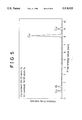
- FIG. 5 is a chart illustrating results of an energy-dispersed type fluorescent X-ray analysis for a spherical body in the first example of the deformed ultra fine grain;
- FIG. 6 is a chart illustrating results of an energy-dispersed type fluorescent X-ray analysis for a tail-like projection in the first example of the deformed ultra fine grain
- FIG. 7 is a photomicrograph showing a second example of a deformed ultra fine grain
- FIG. 8 is a chart illustrating results of an energy-dispersed type fluorescent X-ray analysis for a spherical body in the second example of the deformed ultra fine grain.
- FIG. 9 is a chart illustrating results of an energy-dispersed type fluorescent X-ray analysis for a tail-like projection in the second example of the deformed ultra fine grain.
- a deformed (heteromorphic) ultra-fine grain 1 is formed into a composite type comprising a spherical body 2 of a metal, and a tail-like projection 3 made of a ceramic and projecting from a surface of the spherical body 2.
- the tail-like projection 3 is substantially conical in shape.
- the spherical body 2 has a grain size D in a range represented by D ⁇ 100 nm, and the tail-like projection 3 has a projecting length L in a range represented by L ⁇ 200 nm.
- the deformed ultra-fine grain 1 has the tail-like projection 3 integrally formed thereon, so that the tail-like projection 3 exhibits a separation effect (spacing effect) on adjacent deformed ultra-fine grains 1, thereby avoiding the aggregation of the deformed ultra-fine grains 1 to provide an extremely good dispersion property.
- a process which comprises the steps of: melting a metal blank by plasma arc in a controlled atmosphere including a gas contributing to the formation of a ceramic, thereby forming a large number of spherical metal droplets by the clustering of evaporated particles; and precipitating and growing a ceramic by a reaction of the metal element with the gas on the surfaces of the spherical metal droplets.
- FIGS. 2A to 2E illustrate a mechanism of formation of the deformed ultra-fine grains 1 in such producing process.
- the particles 6 cluster or congregate, i.e., collide, fuse and grow with each other to form spherical metal droplets 7 having a ultra-fine grain size or diameter equal to or less than about 100 nm.
- the spherical metal droplet 7 serves to form the spherical body 2.
- the spherical metal droplet 7 contains the metal element in excess of the content of the metal element in the spherical body 2 and hence, with the cooling of the spherical metal droplet 7, the excessive amount of the metal element is precipitated on the surface thereof to react with the gas G, thereby precipitating the ceramic 8 on the surface of the spherical metal droplet 7.
- the ceramic 8 starts to precipitate and grow into a conical shape.
- the precipitation and growth of the ceramic 8 is completed to form the tail-like projection 3.
- the spherical metal droplet 7 is solidified to form the spherical body 2.
- the spherical body 2 is made of Cu alloy (which will be referred to as an Al-solid solution Cu alloy hereinafter) resulting from incorporation of solid solution aluminum in an amount represented by 17 atom % ⁇ Al ⁇ 19 atom % i.e., in a saturated state, or an intermetallic compound Al 4 Cu 9 .
- the tail-like projection 3 is comprised of AlN.
- the deformed ultra-fine grain 1 having such materials, the migration of electrons is produced for the chemical bonding between the metal portion and the ceramic portion. This exerts a favorable influence on a catalytic reaction which enhances the acceptance and donation of electrons, and the deformed ultra-fine grains 1 do not tend to aggregate. Therefore, if the grains 1 are used as a catalyst element for conversion of an exhaust gas from an automobile engine, they exhibit an excellent catalytic activity.
- the deformed ultra-fine grains 1 are also applicable to gas, temperature and moisture sensors and other sensors.
- a blank comprising aluminum in a content within a range represented by 20 atom % ⁇ Al ⁇ 50 atom % and a balance of copper is used as the alloy blank 4, and nitrogen gas is used as the ceramic forming gas. If required, argon gas may be used along with the nitrogen gas.
- an alloy blank 4 having an aluminum content in a range represented by 20 atom % ⁇ Al ⁇ 30 atom %, e.g., Cu 70 Al 30 (each of the numerical values is atom %) is used, a bulk of deformed ultra-fine grains 1 including a spherical body 2 of an Al-solid solution Cu alloy is produced.
- some deformed ultra-fine grains 1 each including a spherical body 2 of an intermetallic compound Al 4 Cu 9 may be incorporated in a very small amount in the bulk in some cases.
- an alloy blank 4 having an Al content in a range represented by 30 atom % ⁇ Al ⁇ 40 atom %, e.g., Cu 60 Al 40 is used, a bulk of a mixture of both deformed ultra-fine grains 1 each including a spherical body 2 of an Al-solid solution Cu alloy and deformed ultra-fine grains 1 each including a spherical body 2 of an intermetallic compound Al 4 Cu 9 is produced.
- an alloy blank 4 having an Al content in a range represented by 40 atom % ⁇ Al ⁇ 50 %, e.g., Cu 50 Al 50 is used, a bulk of deformed ultra-fine grains 1 each including a spherical body 2 of an intermetallic compound Al 4 Cu 9 is produced.
- some deformed ultra-fine grains 1 each including a spherical body 2 of an Al-solid solution Cu alloy may be incorporated in a very small amount in the bulk in some cases.
- the production of the intermetallic compound Al 4 Cu 9 is started in a range represented by 30 atom % ⁇ Al ⁇ 40 atom %.
- the content of aluminum in the alloy blank 4 is less than 20 atom %, ultra fine grains made of only the Al-solid solution Cu alloy are formed.
- the content of aluminum the alloy blank 4 exceeds 50 atom %, ultra fine grains made of the intermetallic compound Al 4 Cu 9 are formed.
- FIG. 3 illustrates an apparatus for use in the production of a bulk quantity of deformed ultra-fine grains 1.
- This producing apparatus includes a main chamber 9, and a sub-chamber 10 mounted under the main chamber 9.
- the chambers 9 and 10 communicate with each other through a duct 11 and a nozzle 12 mounted on the lower end of the duct 11.
- a tungsten electrode 5 extending into the main chamber 9 and a copper hearth 13 within the main chamber 9 are connected to a power source 14.
- a movable substrate 15 is disposed in the sub-chamber 10 below the nozzle 12.
- the main chamber 9 is connected to a controlled-atmosphere gas supply source 16, while the sub-chamber 10 is connected to a vacuum pump 17.
- a Cu 70 Al 30 alloy blank (each of the numerical values is an atom %) 4 was placed, in an amount of 30 to 50 g, onto the hearth 13.
- the vacuum pump 17 was operated to evacuate the main chamber 9 and the sub-chamber 10, until the pressure within the chambers 9 and 10 reached 1 ⁇ 10 -4 Torrs. Then, the controlled-atmosphere gas supply source 16 was operated to supply argon and nitrogen gases into the main chamber 9. The argon and nitrogen gases in the main chamber 9 were permitted to flow through the duct 11 and the nozzle 12 into the sub-chamber 10 by the operation of the vacuum pump 17 and then flow out of the sub-chamber 10. The amount of argon and nitrogen gases supplied from the controlled-atmosphere gas supply source 16 was adjusted, such that the pressure within the main chamber 9 was brought into a steady state of 600 Torrs.
- FIG. 4 is a photomicrograph (100,000 magnifications) of the deformed ultra-fine grain 1 produced by the above-described producing process using the Cu 70 Al 30 alloy blank 4 (each of the numerical values is an atom %), in which the spherical body 2 and the tail-like projection 3 are observed.
- the grain size D of the spherical body 2 in these deformed ultra-fine grains 1 is in a range represented by 30 nm ⁇ D ⁇ 100 nm; the projecting length L of the tail-like projection 3 is in a range represented by 20 nm ⁇ L ⁇ 200 nm, and the surface area S of the entire grain including the spherical body 2 and the tail-like projection 3 is in a range represented by 3.0 ⁇ 10 -15 m 2 ⁇ S ⁇ 40 ⁇ 10 -15 m 2 .
- FIGS. 5 and 6 show the results of an energy-dispersed type fluorescent X-ray analysis for the deformed ultra-fine grain 1, FIG. 5 corresponding to those for the spherical body 2, and FIG. 6 corresponding to those for the tail-like projection 3.
- the spherical body 2 is an Al-solid solution Cu alloy comprising 83.02 atom % of copper and 16.98 atom % of aluminum.
- the tail-like projection 3 includes Al and thus is AlN.
- FIG. 7 is a photomicrograph (100,000 magnifications) of the deformed ultra-fine grain 1 produced in the above-described producing process using the Cu 50 Al 50 alloy blank 4 (each of the numerical values is an atom %), wherein the spherical body 2 and the tail-like projection 3 are observed.
- the grain size D of the spherical body 2 in these deformed ultra-fine grains 1 is in a range represented by 20 nm ⁇ D ⁇ 80 nm; the projecting length L of the tail-like projection 3 is in a range represented by 20 nm ⁇ L ⁇ 200 nm, and the surface area S of the entire grain including the spherical body 2 and the tail-like projection 3 is in a range represented by 1.5 ⁇ 10 -15 m 2 ⁇ S ⁇ 30 ⁇ 10 -15 m 2 .
- FIGS. 8 and 9 show the results of an energy-dispersed type fluorescent X-ray analysis for the deformed ultra-fine grain 1, FIG. 8 corresponding to those for the spherical body 2, and FIG. 9 corresponding to those for the tail-like projection 3.
- the composition of the spherical body 2 comprises 69.70 atom % of copper and 30.30 atom % of aluminum.
- the spherical body 2 is of an intermetallic compound Al 4 Cu 9 .
- the tail-like projection 3 incudes Al and thus is AlN.
- the preparation of the catalyst was carried out by incorporating the deformed ultra-fine grains 1, each including the spherical body 2 made of the intermetallic compound Al 4 Cu 9 into ⁇ -Al 2 O 3 grains, such that the amount of grains 1 incorporated became 10% by weight, mixing them sufficiently, forming the mixture of the grains into pellets, and sintering the formed pellets.
- helium gas containing 2,000 ppm of NO was allowed to flow through a catalyst layer having 1 g of the catalyst supported thereon at a flow rate of 100 ml/min during a predetermined time under a condition of a reaction temperature of 500° C., and then the gas passed through the catalyst layer was analyzed by a gas chromatography to determine an invert ratio of NO.
- catalysts were prepared using, as a catalyst element, a mixture of 90% by weight of ultra fine grains made of Al 4 Cu 9 having a grain size D in a range represented by 20 nm ⁇ D ⁇ 100 nm, and 10% by weight of ultra fine grains made of AlN having a grain size D in a range represented by 20 nm ⁇ D ⁇ 120 nm, and using single ultra fine grains made of the above-described intermetallic compound Al 4 Cu 9 as another catalyst element. Using these catalysts, a similar NOx conversion test was carried out.
- Table 1 shows the results of the NOx conversion test using these catalysts.
- the catalyst prepared by using the deformed ultra-fine grains 1 as the catalyst element exhibits an excellent catalytic activity which is sustained for a long time.
- the catalyst prepared by using the mixture of ultra-fine grains as the catalyst element with the catalyst prepared by using the single ultra-fine grains as the catalyst element, it was ascertained that their initial performances were substantially the same but after a lapse of 24 hours, there appeared a distinct difference between those two catalysts. This is considered to be due to the catalytic activity of the AlN ultra fine grains in the mixture of ultra fine grains and/or the suppression of the aggregation of the Al 4 Cu 9 ultra fine grains.
Landscapes
- Chemical & Material Sciences (AREA)
- Engineering & Computer Science (AREA)
- Crystallography & Structural Chemistry (AREA)
- Nanotechnology (AREA)
- Materials Engineering (AREA)
- Organic Chemistry (AREA)
- Chemical Kinetics & Catalysis (AREA)
- Powder Metallurgy (AREA)
- Manufacture Of Metal Powder And Suspensions Thereof (AREA)
Abstract
Description
              TABLE 1
______________________________________
             Invert ratio of NO (%)
Catalyst element
               after 30 minutes
                           after 24 hours
______________________________________
Deformed ultra-fine
               35.3        35.1
grains
Mixture of ultra-
               28.1        28.0
fine grains
Single ultra-fine
               28.4        26.5
grains
______________________________________
Claims (24)
Applications Claiming Priority (2)
| Application Number | Priority Date | Filing Date | Title |
|---|---|---|---|
| JP5080036A JP2745372B2 (en) | 1993-03-15 | 1993-03-15 | Method for producing deformed ultrafine particles and aggregates thereof |
| JP5-080036 | 1993-03-15 |
Publications (1)
| Publication Number | Publication Date |
|---|---|
| US5518522A true US5518522A (en) | 1996-05-21 |
Family
ID=13707034
Family Applications (1)
| Application Number | Title | Priority Date | Filing Date |
|---|---|---|---|
| US08/209,148 Expired - Fee Related US5518522A (en) | 1993-03-15 | 1994-03-10 | Deformed ultra fine grains and process for producing same in bulk |
Country Status (3)
| Country | Link |
|---|---|
| US (1) | US5518522A (en) |
| EP (1) | EP0615803A1 (en) |
| JP (1) | JP2745372B2 (en) |
Families Citing this family (4)
| Publication number | Priority date | Publication date | Assignee | Title |
|---|---|---|---|---|
| CN1054781C (en) * | 1995-03-11 | 2000-07-26 | 青岛化工学院 | Manufacture of rare-earth transition metal ultramicron catalyst with nano size hydrogen storing egg-shell type |
| JP3277933B2 (en) * | 2000-04-24 | 2002-04-22 | セイコーエプソン株式会社 | Magnet powder, method for producing bonded magnet, and bonded magnet |
| JP3277932B2 (en) * | 2000-04-24 | 2002-04-22 | セイコーエプソン株式会社 | Magnet powder, method for producing bonded magnet, and bonded magnet |
| KR20260046431A (en) * | 2023-08-03 | 2026-04-07 | 도요타지도샤가부시키가이샤 | Metal particles, a method for manufacturing metal particles, and a dispersion containing metal particles |
Citations (4)
| Publication number | Priority date | Publication date | Assignee | Title |
|---|---|---|---|---|
| US4756746A (en) * | 1986-09-08 | 1988-07-12 | Gte Products Corporation | Process of producing fine spherical particles |
| US4780131A (en) * | 1986-09-08 | 1988-10-25 | Gte Products Corporation | Process for producing spherical light metal based powder particles |
| JPH04280906A (en) * | 1991-03-05 | 1992-10-06 | Shigeo Nakagawa | Manufacture of ultra-fine particle |
| DE4117141A1 (en) * | 1991-05-25 | 1992-11-26 | Wolfgang Seidler | Spherical powder and granules prodn. - by atomising solid rod using plasma jet as former is fed into seal container |
-
1993
- 1993-03-15 JP JP5080036A patent/JP2745372B2/en not_active Expired - Lifetime
-
1994
- 1994-03-10 EP EP94103696A patent/EP0615803A1/en not_active Withdrawn
- 1994-03-10 US US08/209,148 patent/US5518522A/en not_active Expired - Fee Related
Patent Citations (4)
| Publication number | Priority date | Publication date | Assignee | Title |
|---|---|---|---|---|
| US4756746A (en) * | 1986-09-08 | 1988-07-12 | Gte Products Corporation | Process of producing fine spherical particles |
| US4780131A (en) * | 1986-09-08 | 1988-10-25 | Gte Products Corporation | Process for producing spherical light metal based powder particles |
| JPH04280906A (en) * | 1991-03-05 | 1992-10-06 | Shigeo Nakagawa | Manufacture of ultra-fine particle |
| DE4117141A1 (en) * | 1991-05-25 | 1992-11-26 | Wolfgang Seidler | Spherical powder and granules prodn. - by atomising solid rod using plasma jet as former is fed into seal container |
Also Published As
| Publication number | Publication date |
|---|---|
| JP2745372B2 (en) | 1998-04-28 |
| JPH06264101A (en) | 1994-09-20 |
| EP0615803A1 (en) | 1994-09-21 |
Similar Documents
| Publication | Publication Date | Title |
|---|---|---|
| US5429657A (en) | Method for making silver-palladium alloy powders by aerosol decomposition | |
| EP0591881B1 (en) | Method for making palladium and palladium oxide powders by aerosol decomposition | |
| JP2650837B2 (en) | Production method of silver powder by aerosol decomposition | |
| US4046712A (en) | Catalysts sputtered on substantially nonporous low surface area particulate supports | |
| CN1108214C (en) | Method for preparation of golden powder by decomposing aerosol | |
| US5861136A (en) | Method for making copper I oxide powders by aerosol decomposition | |
| US20080006954A1 (en) | Process and Apparatus for Producing Fine Particles | |
| EP0650791B1 (en) | Fine particles of metals, alloys and metal compounds | |
| US4146388A (en) | Molybdenum plasma spray powder, process for producing said powder, and coatings made therefrom | |
| KR20040062566A (en) | Powder for laminated ceramic capacitor internal electrode | |
| EP1205240A1 (en) | Noble metal alloy catalyst for purifying exhaust gases | |
| US5518522A (en) | Deformed ultra fine grains and process for producing same in bulk | |
| JP2545913B2 (en) | Ni-based alloy powder for forming amorphous sprayed coating with excellent corrosion resistance | |
| US20090050857A1 (en) | Method of improving the weatherability of copper powder | |
| US7618475B2 (en) | Metal powder for electrically conductive paste and electrically conductive paste | |
| US3475158A (en) | Production of particulate,non-pyrophoric metals and product | |
| US4810285A (en) | Process for preparing spherical copper fine powder | |
| KR940009339B1 (en) | Method of manufacturing nikel powder | |
| EP0645464A2 (en) | Ultrafine particle of quasi-crystalline aluminum alloy and process for producing aggregate thereof | |
| EP1114684B1 (en) | Method for preparing ultra fine nickel powder | |
| US4942057A (en) | Making an amorphous layer | |
| KR20010020142A (en) | Process for Production of Nickel Powder | |
| EP0721919A1 (en) | Method for making copper (I) oxide powders by aerosol decomposition | |
| CN1013352B (en) | Manufacturing technique of supper-fine molybdenum powder | |
| JPH06264103A (en) | Method for producing ultrafine particles of oxidation-resistant intermetallic compound and aggregate thereof |
Legal Events
| Date | Code | Title | Description |
|---|---|---|---|
| AS | Assignment |
Owner name: MASUMOTO, TSUYOSHI Free format text: ASSIGNMENT OF ASSIGNORS INTEREST;ASSIGNORS:MASUMOTO, TSUYOSHI;INOUE, AKIHISA;YAMAGUCHI, TADASHI;AND OTHERS;REEL/FRAME:007039/0481 Effective date: 19940418 Owner name: INOUE, AKIHISA Free format text: ASSIGNMENT OF ASSIGNORS INTEREST;ASSIGNORS:MASUMOTO, TSUYOSHI;INOUE, AKIHISA;YAMAGUCHI, TADASHI;AND OTHERS;REEL/FRAME:007039/0481 Effective date: 19940418 Owner name: YOSHIDA KOGYO K.K. Free format text: ASSIGNMENT OF ASSIGNORS INTEREST;ASSIGNORS:MASUMOTO, TSUYOSHI;INOUE, AKIHISA;YAMAGUCHI, TADASHI;AND OTHERS;REEL/FRAME:007039/0481 Effective date: 19940418 Owner name: HONDA GIKEN KOGYO KABUSHIKI Free format text: ASSIGNMENT OF ASSIGNORS INTEREST;ASSIGNORS:MASUMOTO, TSUYOSHI;INOUE, AKIHISA;YAMAGUCHI, TADASHI;AND OTHERS;REEL/FRAME:007039/0481 Effective date: 19940418 |
|
| AS | Assignment |
Owner name: YKK CORPORATION, JAPAN Free format text: CHANGE OF NAME;ASSIGNOR:YOSHIDA KOGYO, K.K.;REEL/FRAME:007249/0216 Effective date: 19940801 |
|
| REMI | Maintenance fee reminder mailed | ||
| LAPS | Lapse for failure to pay maintenance fees | ||
| FP | Lapsed due to failure to pay maintenance fee |
Effective date: 20000521 |
|
| STCH | Information on status: patent discontinuation |
Free format text: PATENT EXPIRED DUE TO NONPAYMENT OF MAINTENANCE FEES UNDER 37 CFR 1.362 |