US5502770A - Indirectly sensed signal processing in active periodic acoustic noise cancellation - Google Patents
Indirectly sensed signal processing in active periodic acoustic noise cancellation Download PDFInfo
- Publication number
- US5502770A US5502770A US08/158,328 US15832893A US5502770A US 5502770 A US5502770 A US 5502770A US 15832893 A US15832893 A US 15832893A US 5502770 A US5502770 A US 5502770A
- Authority
- US
- United States
- Prior art keywords
- signal
- noise
- pulse
- signals
- input
- Prior art date
- Legal status (The legal status is an assumption and is not a legal conclusion. Google has not performed a legal analysis and makes no representation as to the accuracy of the status listed.)
- Expired - Lifetime
Links
- 230000000737 periodic effect Effects 0.000 title claims abstract description 6
- 230000005534 acoustic noise Effects 0.000 title claims description 6
- 238000012545 processing Methods 0.000 title abstract description 11
- 238000000034 method Methods 0.000 claims description 9
- 230000008878 coupling Effects 0.000 claims description 7
- 238000010168 coupling process Methods 0.000 claims description 7
- 238000005859 coupling reaction Methods 0.000 claims description 7
- 230000000903 blocking effect Effects 0.000 claims description 6
- 230000002596 correlated effect Effects 0.000 claims description 6
- 238000001914 filtration Methods 0.000 claims description 6
- 238000012544 monitoring process Methods 0.000 claims description 4
- 238000006243 chemical reaction Methods 0.000 claims description 2
- 230000003044 adaptive effect Effects 0.000 description 9
- 239000003990 capacitor Substances 0.000 description 5
- 238000010586 diagram Methods 0.000 description 4
- 238000005094 computer simulation Methods 0.000 description 2
- 238000012937 correction Methods 0.000 description 2
- 230000001627 detrimental effect Effects 0.000 description 2
- 230000003252 repetitive effect Effects 0.000 description 2
- 230000003139 buffering effect Effects 0.000 description 1
- 238000002485 combustion reaction Methods 0.000 description 1
- 239000004020 conductor Substances 0.000 description 1
- 230000001276 controlling effect Effects 0.000 description 1
- 230000000694 effects Effects 0.000 description 1
- 238000011156 evaluation Methods 0.000 description 1
- 230000007246 mechanism Effects 0.000 description 1
- 238000012986 modification Methods 0.000 description 1
- 230000004048 modification Effects 0.000 description 1
- 235000020030 perry Nutrition 0.000 description 1
- 230000009467 reduction Effects 0.000 description 1
- 239000004065 semiconductor Substances 0.000 description 1
Images


Classifications
-
- G—PHYSICS
- G10—MUSICAL INSTRUMENTS; ACOUSTICS
- G10K—SOUND-PRODUCING DEVICES; METHODS OR DEVICES FOR PROTECTING AGAINST, OR FOR DAMPING, NOISE OR OTHER ACOUSTIC WAVES IN GENERAL; ACOUSTICS NOT OTHERWISE PROVIDED FOR
- G10K11/00—Methods or devices for transmitting, conducting or directing sound in general; Methods or devices for protecting against, or for damping, noise or other acoustic waves in general
- G10K11/16—Methods or devices for protecting against, or for damping, noise or other acoustic waves in general
- G10K11/175—Methods or devices for protecting against, or for damping, noise or other acoustic waves in general using interference effects; Masking sound
- G10K11/178—Methods or devices for protecting against, or for damping, noise or other acoustic waves in general using interference effects; Masking sound by electro-acoustically regenerating the original acoustic waves in anti-phase
- G10K11/1785—Methods, e.g. algorithms; Devices
- G10K11/17853—Methods, e.g. algorithms; Devices of the filter
-
- G—PHYSICS
- G10—MUSICAL INSTRUMENTS; ACOUSTICS
- G10K—SOUND-PRODUCING DEVICES; METHODS OR DEVICES FOR PROTECTING AGAINST, OR FOR DAMPING, NOISE OR OTHER ACOUSTIC WAVES IN GENERAL; ACOUSTICS NOT OTHERWISE PROVIDED FOR
- G10K11/00—Methods or devices for transmitting, conducting or directing sound in general; Methods or devices for protecting against, or for damping, noise or other acoustic waves in general
- G10K11/16—Methods or devices for protecting against, or for damping, noise or other acoustic waves in general
- G10K11/175—Methods or devices for protecting against, or for damping, noise or other acoustic waves in general using interference effects; Masking sound
- G10K11/178—Methods or devices for protecting against, or for damping, noise or other acoustic waves in general using interference effects; Masking sound by electro-acoustically regenerating the original acoustic waves in anti-phase
- G10K11/1781—Methods or devices for protecting against, or for damping, noise or other acoustic waves in general using interference effects; Masking sound by electro-acoustically regenerating the original acoustic waves in anti-phase characterised by the analysis of input or output signals, e.g. frequency range, modes, transfer functions
- G10K11/17821—Methods or devices for protecting against, or for damping, noise or other acoustic waves in general using interference effects; Masking sound by electro-acoustically regenerating the original acoustic waves in anti-phase characterised by the analysis of input or output signals, e.g. frequency range, modes, transfer functions characterised by the analysis of the input signals only
- G10K11/17823—Reference signals, e.g. ambient acoustic environment
-
- G—PHYSICS
- G10—MUSICAL INSTRUMENTS; ACOUSTICS
- G10K—SOUND-PRODUCING DEVICES; METHODS OR DEVICES FOR PROTECTING AGAINST, OR FOR DAMPING, NOISE OR OTHER ACOUSTIC WAVES IN GENERAL; ACOUSTICS NOT OTHERWISE PROVIDED FOR
- G10K11/00—Methods or devices for transmitting, conducting or directing sound in general; Methods or devices for protecting against, or for damping, noise or other acoustic waves in general
- G10K11/16—Methods or devices for protecting against, or for damping, noise or other acoustic waves in general
- G10K11/175—Methods or devices for protecting against, or for damping, noise or other acoustic waves in general using interference effects; Masking sound
- G10K11/178—Methods or devices for protecting against, or for damping, noise or other acoustic waves in general using interference effects; Masking sound by electro-acoustically regenerating the original acoustic waves in anti-phase
- G10K11/1785—Methods, e.g. algorithms; Devices
- G10K11/17853—Methods, e.g. algorithms; Devices of the filter
- G10K11/17854—Methods, e.g. algorithms; Devices of the filter the filter being an adaptive filter
-
- G—PHYSICS
- G10—MUSICAL INSTRUMENTS; ACOUSTICS
- G10K—SOUND-PRODUCING DEVICES; METHODS OR DEVICES FOR PROTECTING AGAINST, OR FOR DAMPING, NOISE OR OTHER ACOUSTIC WAVES IN GENERAL; ACOUSTICS NOT OTHERWISE PROVIDED FOR
- G10K11/00—Methods or devices for transmitting, conducting or directing sound in general; Methods or devices for protecting against, or for damping, noise or other acoustic waves in general
- G10K11/16—Methods or devices for protecting against, or for damping, noise or other acoustic waves in general
- G10K11/175—Methods or devices for protecting against, or for damping, noise or other acoustic waves in general using interference effects; Masking sound
- G10K11/178—Methods or devices for protecting against, or for damping, noise or other acoustic waves in general using interference effects; Masking sound by electro-acoustically regenerating the original acoustic waves in anti-phase
- G10K11/1785—Methods, e.g. algorithms; Devices
- G10K11/17855—Methods, e.g. algorithms; Devices for improving speed or power requirements
-
- G—PHYSICS
- G10—MUSICAL INSTRUMENTS; ACOUSTICS
- G10K—SOUND-PRODUCING DEVICES; METHODS OR DEVICES FOR PROTECTING AGAINST, OR FOR DAMPING, NOISE OR OTHER ACOUSTIC WAVES IN GENERAL; ACOUSTICS NOT OTHERWISE PROVIDED FOR
- G10K11/00—Methods or devices for transmitting, conducting or directing sound in general; Methods or devices for protecting against, or for damping, noise or other acoustic waves in general
- G10K11/16—Methods or devices for protecting against, or for damping, noise or other acoustic waves in general
- G10K11/175—Methods or devices for protecting against, or for damping, noise or other acoustic waves in general using interference effects; Masking sound
- G10K11/178—Methods or devices for protecting against, or for damping, noise or other acoustic waves in general using interference effects; Masking sound by electro-acoustically regenerating the original acoustic waves in anti-phase
- G10K11/1787—General system configurations
- G10K11/17879—General system configurations using both a reference signal and an error signal
- G10K11/17883—General system configurations using both a reference signal and an error signal the reference signal being derived from a machine operating condition, e.g. engine RPM or vehicle speed
-
- G—PHYSICS
- G10—MUSICAL INSTRUMENTS; ACOUSTICS
- G10K—SOUND-PRODUCING DEVICES; METHODS OR DEVICES FOR PROTECTING AGAINST, OR FOR DAMPING, NOISE OR OTHER ACOUSTIC WAVES IN GENERAL; ACOUSTICS NOT OTHERWISE PROVIDED FOR
- G10K2210/00—Details of active noise control [ANC] covered by G10K11/178 but not provided for in any of its subgroups
- G10K2210/10—Applications
- G10K2210/121—Rotating machines, e.g. engines, turbines, motors; Periodic or quasi-periodic signals in general
-
- G—PHYSICS
- G10—MUSICAL INSTRUMENTS; ACOUSTICS
- G10K—SOUND-PRODUCING DEVICES; METHODS OR DEVICES FOR PROTECTING AGAINST, OR FOR DAMPING, NOISE OR OTHER ACOUSTIC WAVES IN GENERAL; ACOUSTICS NOT OTHERWISE PROVIDED FOR
- G10K2210/00—Details of active noise control [ANC] covered by G10K11/178 but not provided for in any of its subgroups
- G10K2210/30—Means
- G10K2210/301—Computational
- G10K2210/3028—Filtering, e.g. Kalman filters or special analogue or digital filters
-
- G—PHYSICS
- G10—MUSICAL INSTRUMENTS; ACOUSTICS
- G10K—SOUND-PRODUCING DEVICES; METHODS OR DEVICES FOR PROTECTING AGAINST, OR FOR DAMPING, NOISE OR OTHER ACOUSTIC WAVES IN GENERAL; ACOUSTICS NOT OTHERWISE PROVIDED FOR
- G10K2210/00—Details of active noise control [ANC] covered by G10K11/178 but not provided for in any of its subgroups
- G10K2210/30—Means
- G10K2210/301—Computational
- G10K2210/3032—Harmonics or sub-harmonics
-
- G—PHYSICS
- G10—MUSICAL INSTRUMENTS; ACOUSTICS
- G10K—SOUND-PRODUCING DEVICES; METHODS OR DEVICES FOR PROTECTING AGAINST, OR FOR DAMPING, NOISE OR OTHER ACOUSTIC WAVES IN GENERAL; ACOUSTICS NOT OTHERWISE PROVIDED FOR
- G10K2210/00—Details of active noise control [ANC] covered by G10K11/178 but not provided for in any of its subgroups
- G10K2210/30—Means
- G10K2210/301—Computational
- G10K2210/3045—Multiple acoustic inputs, single acoustic output
Definitions
- the invention relates to the active acoustic cancellation of noise from a periodic source such as repetitive machinery, and in particular to the processing of indirectly sensed signals representative of noise for use as input to an active acoustic noise cancellation system.
- Active noise cancellation involves superimposing on a noise acoustic wave an opposite acoustic wave that destructively interferes with and cancels the noise wave.
- the active noise cancellation principle is most useful at predetermined frequencies in the active noise cancellation range.
- the characteristics of the noise acoustic wave are sensed, a cancelling acoustic wave is produced and delivered to a location through a speaker.
- the combined waves are monitored at the location and a feedback or error signal is produced for iterative adjustment of the cancelling acoustic wave.
- Implementations of the active noise cancellation principle are arranged to accommodate changes in the frequency and intensity characteristics of the noise acoustic wave by incorporating adaptability into the feedback or error path of the active noise cancellation system.
- the changes are accommodated through iterative incremental computations, based on the noise acoustic wave input signal and the error signal, in a procedure known in the art as an algorithm, which in turn is implemented through digital signal processing (DSP) in semiconductor chip active noise controller devices.
- DSP digital signal processing
- Active noise cancelling systems exhibit instability when the cancelling signal gets into the noise acoustic wave prior to the sensing of the characteristics of the noise acoustic wave.
- this has been handled by care in constructing a system to prevent the situation and to some extent by modification of the algorithm to accommodate it.
- a need is present in the art for the ability to correlate an indirectly sensed signal representative of an actual noise acoustic wave with the essential aspects of that actual noise acoustic wave and for a system of using direct and indirect sensing.
- an indirectly sensed signal of a noise acoustic wave is processed into a signal to which a noise cancelling system can respond.
- the processed signal contains the fundamental and the significant harmonic frequencies in the active noise cancellation range,adjusted to the input signal specifications of the active noise cancellation system.
- the processing involves producing sequential pulses in periodic increments where the sequential pulses carry harmonic information and the period is related to the fundamental frequency of the source of the noise, dividing out a numerical increment of the pulses into a single converted pulse per period with a width so that the "on" time of the pulses is about 20% or less, removing all harmonic frequencies above the significant low frequency harmonics and blocking any D.C. at the input to the active noise cancellation system.
- FIG. 1 is a flow chart of the signal processing operations in the invention.
- FIG. 2 is a schematic diagram of the functional blocks in a noise acoustic signal algorithm useable with the invention.
- FIG. 3 is a circuit diagram of an embodiment implementing the operations of FIG. 1.
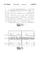
- FIG. 4 is a print of a computer simulation of the relative timing in operation of the circuit of FIG. 3.
- FIG. 5 is a graph of the signals at points in the circuit of FIG. 3.
- the acoustic noise sound wave is estimated and is acoustically cancelled by a cancelling signal which is a convolution of an input signal of the noise sound wave and the output of an adaptive filter that corrects any correlated error between the noise sound wave and the cancelling sound wave.
- the amount of noise reduction is greatly affected by the degree of correlation between the noise acoustic wave and the input signal representing it.
- a noise signal, acoustically picked up close to the source of the noise is closely correlated with the noise but not always easily useable.
- indirectly picked up noise signals have not been correlated with the noise principally because the sound power is concentrated at frequencies lower than the repeating frequency.
- the invention provides principles and operations in implementing them for the use of an indirectly sensed signal of noise having sequential pulses within a repeating period as an input to a noise acoustic wave cancelling system. While the invention is useful in active sound cancellation where the mechanism that generates the noise acoustic wave can be caused to produce a sequential series of pulses within repetitive periods, the invention is particularly useful in sound cancellation with rotary machinery such as an engine where the repeating period is a revolution, and the sequential pulses are producible by sensing, as is done in many tachometers, the passing of teeth on a wheel mounted on a crankshaft.
- the principles of the invention are illustrated in connection with the cancellation of the noise acoustic wave produced by an internal combustion engine using a tachometer type indirectly sensed signal that is processed in accordance with the invention to be representative of that noise acoustic wave.
- the processing involves providing a signal in the form of sequential digital pulses within periods related to the fundamental frequency of the noise wherein the periods carry information related to the fundamental frequency and the pulses carry information related to the harmonics, controlling the power to be compatible with the rapid convergence of a sound cancellation algorithm and generating an analog signal correlated with the fundamental and significant low frequency harmonics that meets the specifications of the input of an active sound cancellation system.
- the principles of the invention are achieved in an embodiment involving the RPM of an engine, by providing a tachometer type RPM signal of a stream of pulses with a specific number per revolution,dividing out an increment of those pulses to form the basis of a single converted pulse per revolution signal, the pulse width of which is arranged to be "on" 20% or less of the time.
- the amplitude of the single pulse per revolution signal is adjusted, all harmonics above a predetermined value are removed with a low pass filter and any D.C is capacitively isolated from the input of the sound cancellation algorithm.
- the predetermined value is approximately 500 Hz.
- the analog signal of the fundamental and significant low frequency harmonic frequencies serves as an input signal for an active noise cancellation system.
- a flow chart is provided of the signal processing operations of the invention.
- element 1 there is the generation of a signal having the characteristics that there are a series of pulses within a repeating period.
- a tachometer type signal having a series of pulses each revolution of the engine will contain the frequency information needed for an input signal to an adaptive Filtered X type of algorithm in an active noise cancellation system.
- an increment of the pulses are divided out of the tachometer type stream of pulses signal and are converted to a single shaped pulse per period which in this example is a revolution with a selected width or "on time".
- a counter can accomplish the pulse count and a logic circuit with inputs from appropriate locations in the counter can terminate the single pulse at the selected width.
- a third operation labelled element 3 the amplitude of the "single pulse per revolution" signal which at this point is essentially the output level of the elements of the counter and logic circuit is adjusted for power level and compatibility with subsequent filtering and input specifications of the noise cancellation system to which it is to be attached.
- a fourth operation labelled element 4 the signal is subjected to low pass filtering with a cut off frequency of a predetermined frequency, such as, for example about 500 Hz, to preserve all low frequency significant harmonics while eliminating the higher frequency harmonics. Harmonics at frequencies higher than the predetermined value produce an effect known in the art as aliasing and are detrimental to the efficient operation of the cancellation system algorithm.
- a predetermined frequency such as, for example about 500 Hz
- any direct current present at the interface with the noise cancellation system is blocked. This is conveniently done with capacitive coupling that passes the analog signal containing the fundamental and low frequency harmonics only.
- the resulting signal from the operations of FIG.1 contains the fundamental and low significant harmonic frequency information under specifications compatible with the input requirements of the Adaptive Filtered X Least Mean Squares (LMS) type of algorithm in a noise cancellation system.
- LMS Adaptive Filtered X Least Mean Squares
- FIG. 2 there is shown a diagram of the functional blocks in a state of the art Adaptive Filtered X Least Mean Squares type of algorithm in a noise cancellation system to which the processed signal of FIG. 1 is applied as an input at either of terminals 6 or 7.
- the processed signal in accordance with the invention it becomes possible to introduce into a state of the art noise cancellation system both indirectly sensed type noise input signals at one input terminal such as terminal 6 and direct acoustically sensed type noise input signals at another input terminal such as terminal 7.
- the elements represent the functions of variables that influence the cancelling signal.
- the algorithm operates by calculating a correction based on an error signal, adjusting an adaptive filter for the cancelling signal which is delivered to the location where the noise is to be cancelled through a speaker which is monitored by a monitoring microphone in the cancellation signal path between the adaptive filter and the summing element.
- the corrections are repeated in a series of cycles until a minimum variation is achieved.
- Noise cancellation controllers with adaptive algorithms as in FIG. 2 are available commercially as integrated circuits. Analog to digital conversion for the internal digital signal processing (DSP) in the algorithm is done in the integrated circuit of the controller. Such controllers however have certain characteristics that place some limitations on an input signal for compatibility.
- FIGS. 3, 4 and 5 a circuit embodiment is shown that implements the principles of the invention, in which FIG. 3 is a diagram of the circuit, FIG. 4 is a computer simulation of signal levels at points in the circuit and FIG. 5 shows the signals at the input node, at the output node and at an intermediate node location following the division operation 2 of FIG. 1.
- the signal at the input node 10 is produced by a tachometer type RPM signal generator 11 with a ten toothed wheel driven by the crankshaft of the engine,not shown,having a magnetic pickup 13 and pulse defining electronics 14.
- the input signal at input node 10 is thus a series of ten serial pulses in a period defined by each revolution of the engine.
- the input pulses are shown in FIG.4 as signal trace A, and in FIG. 5 as signal trace B.
- the division operation 2 of FIG. 1 is provided in FIG. 3 by a counter section 15 in dotted outline, and a logic section 16 in dotted outline, that together produce a single pulse at node 17, shown as trace C in FIG. 4 and trace D in FIG.
- the counter section 15 is made up of a series of four bistable switching elements 18, 19, 20, and 21, known in the art as flip-flops.
- the switching elements 18-21 are connected as a binary counter, the output of which is followed by an inverter element 22.
- Each switching element taking element 18 for explanation, has a clock input 23, an "on” output 24, an "off” output 25, a "set” input 26 and a “clear” input 27.
- Elements 28, 29, 30, 31 and 32 perform the respective same functions for switching element 19; 33, 34, 35, 36, and 37 for switching element 20; and, 38, 39, 40, 41 and 42 for switching element 21.
- Each switching element is connected for bistable operation by a conductor labelled element 43, 44, 45,and 46 from the "off" output to the "set” input for each of the switching elements 18-21.
- the logic section 16 is a four input "Nand” element 47 having positive signal inputs 48, 49, 50 and 51 and delivering a negative output signal on line 52 that in turn is connected to the "clear" terminals 27, 32, 37 and 42 of the switching elements 18-21.
- the "clear" signal is shown in FIG. 4 as trace E.
- the signal out of the Nand element 47 clears all switching elements 18-21, setting the "off" terminals 25, 30, 35 and 40 "high” and the "on” terminals 24, 29,34 and 39 “low”.
- the Nand 47 inputs 48-51 are connected to sense that elements 18 and 21 of the counter are "off” and elements 19 and 20 are on.
- the traces F, G, H, and I in FIG. 4 are the levels at outputs 24, 29, 34 and 39 respectively in the circuit of FIG. 3 during the pulses at node 10 during a revolution of the wheel 12.
- the division circuitry of the counter 15 and logic element 16 is thus a function of the number of teeth in the wheel 12.
- the signal from the Nand 47 clears all elements 18-21 setting output 39 low which is inverted by element 22 to provide the lead portion of the pulses in trace D of FIG. 5 and trace C of FIG. 4.
- the counter then counts pulses to a point where the output 39 is high at which point the inverter 22 provides the terminating negative shift for the single pulse as shown in trace C of FIG. 4 and trace D of FIG. 5.
- the width of the single pulse per revolution pulses of traces C and D is selectable by the count in the counter delivered on the inputs to the Nand circuit and is selected to be about 20% of the leading shifts of the pulses, that is, the frequency of the pulses.
- the amplitude adjustment operation 3 of FIG. 1 is achieved in FIG. 3 by a section 55 in dotted outline wherein the amplitude of the signal is reduced to a selected magnitude with a variable resistance 56 with one terminal connected to ground and the signal passed through capacitive coupling 57 to the next stage.
- the low pass filter operation 4 of FIG. 1 is achieved in FIG. 3 by a section 58 in dotted outline, made up of an isolating buffering operational amplifier 59 and a standard in the art low frequency passing filter circuit made up of two resistances 60 and 61 in series with an operational amplifier 62 and having one capacitor 63 connected from a point between the resistors 60 and 61 to the output of the operational amplifier 62 and with another capacitor 64 connected from the input of the operational amplifier to ground.
- the D.C. blocking operation 5 of FIG. 1 is achieved in FIG. 3 by a capacitive coupling 65 between the output of the operational amplifier 62 and the output node 66 of the circuit.
- a signal trace J illustrates the analog output signal at node 66 that serves as the input to the noise cancellation system in FIG. 2.
- a switch for convenience in assembling a system may be placed in the line between the operational amplifier 62 output and the capacitive coupling 65.
Landscapes
- Physics & Mathematics (AREA)
- Engineering & Computer Science (AREA)
- Acoustics & Sound (AREA)
- Multimedia (AREA)
- Soundproofing, Sound Blocking, And Sound Damping (AREA)
Abstract
Description
Claims (17)
Priority Applications (5)
| Application Number | Priority Date | Filing Date | Title |
|---|---|---|---|
| US08/158,328 US5502770A (en) | 1993-11-29 | 1993-11-29 | Indirectly sensed signal processing in active periodic acoustic noise cancellation |
| JP7515072A JPH08506433A (en) | 1993-11-29 | 1994-10-27 | Indirectly detected signal processing in active periodic acoustic noise cancellation systems |
| EP94932098A EP0681727B1 (en) | 1993-11-29 | 1994-10-27 | Indirectly sensed signal processing in active periodic acoustic noise cancellation |
| PCT/US1994/012399 WO1995014988A1 (en) | 1993-11-29 | 1994-10-27 | Indirectly sensed signal processing in active periodic acoustic noise cancellation |
| DE69424932T DE69424932T2 (en) | 1993-11-29 | 1994-10-27 | INDIRECTLY SCANNED SIGNAL PROCESSING IN ACTIVE PERIODIC NOISE REDUCTION |
Applications Claiming Priority (1)
| Application Number | Priority Date | Filing Date | Title |
|---|---|---|---|
| US08/158,328 US5502770A (en) | 1993-11-29 | 1993-11-29 | Indirectly sensed signal processing in active periodic acoustic noise cancellation |
Publications (1)
| Publication Number | Publication Date |
|---|---|
| US5502770A true US5502770A (en) | 1996-03-26 |
Family
ID=22567623
Family Applications (1)
| Application Number | Title | Priority Date | Filing Date |
|---|---|---|---|
| US08/158,328 Expired - Lifetime US5502770A (en) | 1993-11-29 | 1993-11-29 | Indirectly sensed signal processing in active periodic acoustic noise cancellation |
Country Status (5)
| Country | Link |
|---|---|
| US (1) | US5502770A (en) |
| EP (1) | EP0681727B1 (en) |
| JP (1) | JPH08506433A (en) |
| DE (1) | DE69424932T2 (en) |
| WO (1) | WO1995014988A1 (en) |
Cited By (14)
| Publication number | Priority date | Publication date | Assignee | Title |
|---|---|---|---|---|
| US5987144A (en) * | 1995-04-04 | 1999-11-16 | Technofirst | Personal active noise cancellation method and device having invariant impulse response |
| US6622647B2 (en) | 2001-06-26 | 2003-09-23 | Depoy Martin L. | Active noise cancellation for a torpedo seeker head |
| US20050123407A1 (en) * | 2003-12-04 | 2005-06-09 | York International Corporation | System and method for noise attenuation of screw compressors |
| US7050516B2 (en) * | 2003-03-20 | 2006-05-23 | Broadcom Corporation | System and method for periodic noise avoidance in data transmission systems |
| US20080144853A1 (en) * | 2006-12-06 | 2008-06-19 | Sommerfeldt Scott D | Secondary Path Modeling for Active Noise Control |
| WO2008091977A3 (en) * | 2007-01-24 | 2008-09-25 | Johnson Controls Tech Co | System and method of operation of multiple screw compressors with continuously variable speed to provide noise cancellation |
| US20090086990A1 (en) * | 2007-09-27 | 2009-04-02 | Markus Christoph | Active noise control using bass management |
| US20090105036A1 (en) * | 2007-10-23 | 2009-04-23 | Caterpillar Inc. | Drop box for powertrain |
| US20090147965A1 (en) * | 2007-12-07 | 2009-06-11 | Kuo Sen M | Electronic pillow for abating snoring/environmental noises, hands-free communications, and non-invasive monitoring and recording |
| US20120186271A1 (en) * | 2009-09-29 | 2012-07-26 | Koninklijke Philips Electronics N.V. | Noise reduction for an acoustic cooling system |
| US20130182865A1 (en) * | 2011-12-30 | 2013-07-18 | Agco Corporation | Acoustic fault detection of mechanical systems with active noise cancellation |
| US20140277930A1 (en) * | 2013-03-12 | 2014-09-18 | Davis Y. Pan | Motor Vehicle Active Noise Reduction |
| US9247346B2 (en) | 2007-12-07 | 2016-01-26 | Northern Illinois Research Foundation | Apparatus, system and method for noise cancellation and communication for incubators and related devices |
| US20170229111A1 (en) * | 2014-08-05 | 2017-08-10 | Panasonic Intellectual Property Management Co., Ltd. | Signal processing device, program, and range hood device |
Families Citing this family (1)
| Publication number | Priority date | Publication date | Assignee | Title |
|---|---|---|---|---|
| GB9920883D0 (en) | 1999-09-03 | 1999-11-10 | Titon Hardware | Ventilation assemblies |
Citations (30)
| Publication number | Priority date | Publication date | Assignee | Title |
|---|---|---|---|---|
| US4122303A (en) * | 1976-12-10 | 1978-10-24 | Sound Attenuators Limited | Improvements in and relating to active sound attenuation |
| US4153815A (en) * | 1976-05-13 | 1979-05-08 | Sound Attenuators Limited | Active attenuation of recurring sounds |
| DE3106029A1 (en) * | 1981-02-19 | 1982-09-09 | Volkswagenwerk Ag, 3180 Wolfsburg | Method and arrangement for reducing the noise level in the head region of motor vehicle occupants |
| US4417098A (en) * | 1979-08-16 | 1983-11-22 | Sound Attenuators Limited | Method of reducing the adaption time in the cancellation of repetitive vibration |
| US4423289A (en) * | 1979-06-28 | 1983-12-27 | National Research Development Corporation | Signal processing systems |
| US4480333A (en) * | 1981-04-15 | 1984-10-30 | National Research Development Corporation | Method and apparatus for active sound control |
| US4489441A (en) * | 1979-11-21 | 1984-12-18 | Sound Attenuators Limited | Method and apparatus for cancelling vibration |
| US4490841A (en) * | 1981-10-21 | 1984-12-25 | Sound Attenuators Limited | Method and apparatus for cancelling vibrations |
| US4506380A (en) * | 1982-07-07 | 1985-03-19 | Nissan Motor Company, Limited | Method and apparatus for controlling the sound field in a vehicle cabin or the like |
| US4527282A (en) * | 1981-08-11 | 1985-07-02 | Sound Attenuators Limited | Method and apparatus for low frequency active attenuation |
| US4566118A (en) * | 1981-11-26 | 1986-01-21 | Sound Attenuators Limited | Method of and apparatus for cancelling vibrations from a source of repetitive vibrations |
| US4589133A (en) * | 1983-06-23 | 1986-05-13 | National Research Development Corp. | Attenuation of sound waves |
| US4596033A (en) * | 1984-02-21 | 1986-06-17 | National Research Development Corp. | Attenuation of sound waves |
| US4600863A (en) * | 1982-04-19 | 1986-07-15 | Sound Attenuators Limited | Method of and apparatus for active vibration isolation |
| US4637048A (en) * | 1984-03-07 | 1987-01-13 | National Research Development Corp. | Methods and apparatus for reducing noise by cancellation |
| US4654871A (en) * | 1981-06-12 | 1987-03-31 | Sound Attenuators Limited | Method and apparatus for reducing repetitive noise entering the ear |
| US4669122A (en) * | 1984-06-21 | 1987-05-26 | National Research Development Corporation | Damping for directional sound cancellation |
| US4862506A (en) * | 1988-02-24 | 1989-08-29 | Noise Cancellation Technologies, Inc. | Monitoring, testing and operator controlling of active noise and vibration cancellation systems |
| EP0340974A2 (en) * | 1988-05-04 | 1989-11-08 | Nelson Industries, Inc. | Active acoustic attenuation system with differential filtering |
| US4977600A (en) * | 1988-06-07 | 1990-12-11 | Noise Cancellation Technologies, Inc. | Sound attenuation system for personal seat |
| US4987598A (en) * | 1990-05-03 | 1991-01-22 | Nelson Industries | Active acoustic attenuation system with overall modeling |
| US5052510A (en) * | 1990-02-16 | 1991-10-01 | Noise Cancellation Technologies, Inc. | Hybrid type vibration isolation apparatus |
| US5097923A (en) * | 1988-02-19 | 1992-03-24 | Noise Cancellation Technologies, Inc. | Active sound attenation system for engine exhaust systems and the like |
| EP0479367A2 (en) * | 1990-10-04 | 1992-04-08 | General Motors Corporation | Method and apparatus for attenuating engine generated noise |
| US5105377A (en) * | 1990-02-09 | 1992-04-14 | Noise Cancellation Technologies, Inc. | Digital virtual earth active cancellation system |
| US5126681A (en) * | 1989-10-16 | 1992-06-30 | Noise Cancellation Technologies, Inc. | In-wire selective active cancellation system |
| US5219037A (en) * | 1992-01-21 | 1993-06-15 | General Motors Corporation | Component mount assembly providing active control of vehicle vibration |
| US5222148A (en) * | 1992-04-29 | 1993-06-22 | General Motors Corporation | Active noise control system for attenuating engine generated noise |
| US5221185A (en) * | 1991-08-05 | 1993-06-22 | General Electric Company | Method and apparatus for synchronizing rotating machinery to reduce noise |
| GB2265277A (en) * | 1992-03-17 | 1993-09-22 | Fuji Heavy Ind Ltd | Noise reduction system for automobile compartment |
-
1993
- 1993-11-29 US US08/158,328 patent/US5502770A/en not_active Expired - Lifetime
-
1994
- 1994-10-27 JP JP7515072A patent/JPH08506433A/en active Pending
- 1994-10-27 WO PCT/US1994/012399 patent/WO1995014988A1/en not_active Ceased
- 1994-10-27 DE DE69424932T patent/DE69424932T2/en not_active Expired - Lifetime
- 1994-10-27 EP EP94932098A patent/EP0681727B1/en not_active Expired - Lifetime
Patent Citations (31)
| Publication number | Priority date | Publication date | Assignee | Title |
|---|---|---|---|---|
| US4153815A (en) * | 1976-05-13 | 1979-05-08 | Sound Attenuators Limited | Active attenuation of recurring sounds |
| US4122303A (en) * | 1976-12-10 | 1978-10-24 | Sound Attenuators Limited | Improvements in and relating to active sound attenuation |
| US4423289A (en) * | 1979-06-28 | 1983-12-27 | National Research Development Corporation | Signal processing systems |
| US4417098A (en) * | 1979-08-16 | 1983-11-22 | Sound Attenuators Limited | Method of reducing the adaption time in the cancellation of repetitive vibration |
| US4489441A (en) * | 1979-11-21 | 1984-12-18 | Sound Attenuators Limited | Method and apparatus for cancelling vibration |
| DE3106029A1 (en) * | 1981-02-19 | 1982-09-09 | Volkswagenwerk Ag, 3180 Wolfsburg | Method and arrangement for reducing the noise level in the head region of motor vehicle occupants |
| US4480333A (en) * | 1981-04-15 | 1984-10-30 | National Research Development Corporation | Method and apparatus for active sound control |
| US4654871A (en) * | 1981-06-12 | 1987-03-31 | Sound Attenuators Limited | Method and apparatus for reducing repetitive noise entering the ear |
| US4527282A (en) * | 1981-08-11 | 1985-07-02 | Sound Attenuators Limited | Method and apparatus for low frequency active attenuation |
| US4490841A (en) * | 1981-10-21 | 1984-12-25 | Sound Attenuators Limited | Method and apparatus for cancelling vibrations |
| US4566118A (en) * | 1981-11-26 | 1986-01-21 | Sound Attenuators Limited | Method of and apparatus for cancelling vibrations from a source of repetitive vibrations |
| US4600863A (en) * | 1982-04-19 | 1986-07-15 | Sound Attenuators Limited | Method of and apparatus for active vibration isolation |
| US4506380A (en) * | 1982-07-07 | 1985-03-19 | Nissan Motor Company, Limited | Method and apparatus for controlling the sound field in a vehicle cabin or the like |
| US4589133A (en) * | 1983-06-23 | 1986-05-13 | National Research Development Corp. | Attenuation of sound waves |
| US4596033A (en) * | 1984-02-21 | 1986-06-17 | National Research Development Corp. | Attenuation of sound waves |
| US4637048A (en) * | 1984-03-07 | 1987-01-13 | National Research Development Corp. | Methods and apparatus for reducing noise by cancellation |
| US4669122A (en) * | 1984-06-21 | 1987-05-26 | National Research Development Corporation | Damping for directional sound cancellation |
| US5097923A (en) * | 1988-02-19 | 1992-03-24 | Noise Cancellation Technologies, Inc. | Active sound attenation system for engine exhaust systems and the like |
| US4862506A (en) * | 1988-02-24 | 1989-08-29 | Noise Cancellation Technologies, Inc. | Monitoring, testing and operator controlling of active noise and vibration cancellation systems |
| EP0340974A2 (en) * | 1988-05-04 | 1989-11-08 | Nelson Industries, Inc. | Active acoustic attenuation system with differential filtering |
| US4977600A (en) * | 1988-06-07 | 1990-12-11 | Noise Cancellation Technologies, Inc. | Sound attenuation system for personal seat |
| US5126681A (en) * | 1989-10-16 | 1992-06-30 | Noise Cancellation Technologies, Inc. | In-wire selective active cancellation system |
| US5105377A (en) * | 1990-02-09 | 1992-04-14 | Noise Cancellation Technologies, Inc. | Digital virtual earth active cancellation system |
| US5052510A (en) * | 1990-02-16 | 1991-10-01 | Noise Cancellation Technologies, Inc. | Hybrid type vibration isolation apparatus |
| US4987598A (en) * | 1990-05-03 | 1991-01-22 | Nelson Industries | Active acoustic attenuation system with overall modeling |
| EP0479367A2 (en) * | 1990-10-04 | 1992-04-08 | General Motors Corporation | Method and apparatus for attenuating engine generated noise |
| US5146505A (en) * | 1990-10-04 | 1992-09-08 | General Motors Corporation | Method for actively attenuating engine generated noise |
| US5221185A (en) * | 1991-08-05 | 1993-06-22 | General Electric Company | Method and apparatus for synchronizing rotating machinery to reduce noise |
| US5219037A (en) * | 1992-01-21 | 1993-06-15 | General Motors Corporation | Component mount assembly providing active control of vehicle vibration |
| GB2265277A (en) * | 1992-03-17 | 1993-09-22 | Fuji Heavy Ind Ltd | Noise reduction system for automobile compartment |
| US5222148A (en) * | 1992-04-29 | 1993-06-22 | General Motors Corporation | Active noise control system for attenuating engine generated noise |
Non-Patent Citations (4)
| Title |
|---|
| D. C. Perry et al. The Use of DSP for Adaptive Noise Cancellation for Road Vehicles Session 3, Paper 3, pp. 3.3.1 to 3.3.8. * |
| D. C. Perry et al.--"The Use of DSP for Adaptive Noise Cancellation for Road Vehicles"--Session 3, Paper 3, pp. 3.3.1 to 3.3.8. |
| J. C. Stevens An Experimental Evaluation of Adaptive Filtering Algorithms for Active Noise Control GRTI/AERO pp. 1 10. * |
| J. C. Stevens--"An Experimental Evaluation of Adaptive Filtering Algorithms for Active Noise Control" GRTI/AERO pp. 1-10. |
Cited By (24)
| Publication number | Priority date | Publication date | Assignee | Title |
|---|---|---|---|---|
| US5987144A (en) * | 1995-04-04 | 1999-11-16 | Technofirst | Personal active noise cancellation method and device having invariant impulse response |
| US6622647B2 (en) | 2001-06-26 | 2003-09-23 | Depoy Martin L. | Active noise cancellation for a torpedo seeker head |
| US7050516B2 (en) * | 2003-03-20 | 2006-05-23 | Broadcom Corporation | System and method for periodic noise avoidance in data transmission systems |
| US20050123407A1 (en) * | 2003-12-04 | 2005-06-09 | York International Corporation | System and method for noise attenuation of screw compressors |
| US7387498B2 (en) | 2003-12-04 | 2008-06-17 | York International Corporation | System and method for noise attenuation of screw compressors |
| US8270625B2 (en) | 2006-12-06 | 2012-09-18 | Brigham Young University | Secondary path modeling for active noise control |
| US20080144853A1 (en) * | 2006-12-06 | 2008-06-19 | Sommerfeldt Scott D | Secondary Path Modeling for Active Noise Control |
| WO2008091977A3 (en) * | 2007-01-24 | 2008-09-25 | Johnson Controls Tech Co | System and method of operation of multiple screw compressors with continuously variable speed to provide noise cancellation |
| US7854596B2 (en) | 2007-01-24 | 2010-12-21 | Johnson Controls Technology Company | System and method of operation of multiple screw compressors with continuously variable speed to provide noise cancellation |
| US8559648B2 (en) * | 2007-09-27 | 2013-10-15 | Harman Becker Automotive Systems Gmbh | Active noise control using bass management |
| US20090086990A1 (en) * | 2007-09-27 | 2009-04-02 | Markus Christoph | Active noise control using bass management |
| US8365637B2 (en) | 2007-10-23 | 2013-02-05 | Caterpillar Inc. | Drop box for powertrain |
| US20090105036A1 (en) * | 2007-10-23 | 2009-04-23 | Caterpillar Inc. | Drop box for powertrain |
| US8325934B2 (en) | 2007-12-07 | 2012-12-04 | Board Of Trustees Of Northern Illinois University | Electronic pillow for abating snoring/environmental noises, hands-free communications, and non-invasive monitoring and recording |
| US20090147965A1 (en) * | 2007-12-07 | 2009-06-11 | Kuo Sen M | Electronic pillow for abating snoring/environmental noises, hands-free communications, and non-invasive monitoring and recording |
| US9247346B2 (en) | 2007-12-07 | 2016-01-26 | Northern Illinois Research Foundation | Apparatus, system and method for noise cancellation and communication for incubators and related devices |
| US9542924B2 (en) | 2007-12-07 | 2017-01-10 | Northern Illinois Research Foundation | Apparatus, system and method for noise cancellation and communication for incubators and related devices |
| US9858915B2 (en) | 2007-12-07 | 2018-01-02 | Northern Illinois Research Foundation | Apparatus, system and method for noise cancellation and communication for incubators and related devices |
| US20120186271A1 (en) * | 2009-09-29 | 2012-07-26 | Koninklijke Philips Electronics N.V. | Noise reduction for an acoustic cooling system |
| US20130182865A1 (en) * | 2011-12-30 | 2013-07-18 | Agco Corporation | Acoustic fault detection of mechanical systems with active noise cancellation |
| US20140277930A1 (en) * | 2013-03-12 | 2014-09-18 | Davis Y. Pan | Motor Vehicle Active Noise Reduction |
| US9118987B2 (en) * | 2013-03-12 | 2015-08-25 | Bose Corporation | Motor vehicle active noise reduction |
| US20170229111A1 (en) * | 2014-08-05 | 2017-08-10 | Panasonic Intellectual Property Management Co., Ltd. | Signal processing device, program, and range hood device |
| US10229666B2 (en) * | 2014-08-05 | 2019-03-12 | Panasonic Intellectual Property Management Co., Ltd. | Signal processing device, program, and range hood device |
Also Published As
| Publication number | Publication date |
|---|---|
| JPH08506433A (en) | 1996-07-09 |
| EP0681727B1 (en) | 2000-06-14 |
| WO1995014988A1 (en) | 1995-06-01 |
| DE69424932D1 (en) | 2000-07-20 |
| DE69424932T2 (en) | 2001-02-01 |
| EP0681727A1 (en) | 1995-11-15 |
Similar Documents
| Publication | Publication Date | Title |
|---|---|---|
| US5502770A (en) | Indirectly sensed signal processing in active periodic acoustic noise cancellation | |
| EP0596971B1 (en) | Noise reduction system | |
| US5426705A (en) | Vehicle internal noise reduction system | |
| US4654871A (en) | Method and apparatus for reducing repetitive noise entering the ear | |
| US4012942A (en) | Borderline spark knock detector | |
| US5140640A (en) | Noise cancellation system | |
| EP0568128A2 (en) | Noise attenuation system | |
| EP0568127A2 (en) | Noise attenuation system | |
| EP0568129A2 (en) | Noise attenuation system | |
| JPH0511783A (en) | Active vibration control device | |
| US5295192A (en) | Electronic noise attenuation method and apparatus for use in effecting such method | |
| EP0410685B1 (en) | System for reducing noise level in vehicular cabin | |
| US4855944A (en) | Noise generator with shaped spectrum | |
| WO1989000746A1 (en) | Improvements relating to noise reduction systems | |
| EP0492680A2 (en) | Method and apparatus for attenuating noise | |
| JP3646809B2 (en) | Time domain adaptive control system | |
| GB2273849A (en) | Vehicle active noise reduction system | |
| US5487027A (en) | Process and apparatus for providing an analog waveform synchronized with an input signal | |
| JP3411611B2 (en) | Noise cancellation method | |
| JP3506449B2 (en) | Noise control device | |
| JP2635496B2 (en) | Noise control device | |
| EP4390917A1 (en) | Apparatus, system, and method for providing a fast-acting engine order cancellation | |
| JPH0211047B2 (en) | ||
| WO1994029847A1 (en) | Three dimensional sound control with active noise cancellation | |
| JP3471375B2 (en) | Active vibration noise control device |
Legal Events
| Date | Code | Title | Description |
|---|---|---|---|
| AS | Assignment |
Owner name: CATERPILLAR INC., ILLINOIS Free format text: ASSIGNMENT OF ASSIGNORS INTEREST;ASSIGNORS:KUO, SEN M.;JI, MINJIANG;CHRISTENSEN, M. KATHRYN;AND OTHERS;REEL/FRAME:006920/0504;SIGNING DATES FROM 19931208 TO 19940115 |
|
| STCF | Information on status: patent grant |
Free format text: PATENTED CASE |
|
| AS | Assignment |
Owner name: NORTHERN ILLINOIS UNIVERSITY, ILLINOIS Free format text: ASSIGNMENT OF ASSIGNORS INTEREST;ASSIGNOR:CATERPILLAR INC.;REEL/FRAME:007975/0286 Effective date: 19960603 |
|
| CC | Certificate of correction | ||
| FPAY | Fee payment |
Year of fee payment: 4 |
|
| FPAY | Fee payment |
Year of fee payment: 8 |
|
| FPAY | Fee payment |
Year of fee payment: 12 |