US5486742A - Easily started DC motor apparatus - Google Patents
Easily started DC motor apparatus Download PDFInfo
- Publication number
- US5486742A US5486742A US08/183,775 US18377594A US5486742A US 5486742 A US5486742 A US 5486742A US 18377594 A US18377594 A US 18377594A US 5486742 A US5486742 A US 5486742A
- Authority
- US
- United States
- Prior art keywords
- motor
- current
- coils
- pulsating
- rotor
- Prior art date
- Legal status (The legal status is an assumption and is not a legal conclusion. Google has not performed a legal analysis and makes no representation as to the accuracy of the status listed.)
- Expired - Fee Related
Links
Images


Classifications
-
- H—ELECTRICITY
- H02—GENERATION; CONVERSION OR DISTRIBUTION OF ELECTRIC POWER
- H02P—CONTROL OR REGULATION OF ELECTRIC MOTORS, ELECTRIC GENERATORS OR DYNAMO-ELECTRIC CONVERTERS; CONTROLLING TRANSFORMERS, REACTORS OR CHOKE COILS
- H02P6/00—Arrangements for controlling synchronous motors or other dynamo-electric motors using electronic commutation dependent on the rotor position; Electronic commutators therefor
- H02P6/14—Electronic commutators
- H02P6/16—Circuit arrangements for detecting position
- H02P6/18—Circuit arrangements for detecting position without separate position detecting elements
- H02P6/185—Circuit arrangements for detecting position without separate position detecting elements using inductance sensing, e.g. pulse excitation
Definitions
- the present invention relates to a DC motor apparatus, and more particularly, to & DC motor which can be started with a small starting current.
- a magnetic path is formed by a magnetic material section to enhance a magnetic flux density generated by a coil.
- a magnetic flux from a permanent magnet incorporated in a movable part of a motor converges in such a magnetic material section having high permeability. Therefore, since an intensive magnetic attracting force is generated between the permanent magnet and the magnetic material section it is necessary to supply a large exciting current from a power supply to such a DC motor.
- FIG. 1 is a cross-sectional view indicating magnetic pole portions of a rotor and a stator of an ordinary DC motor.
- a permanent magnet 1 of the rotor has magnetic poles arranged alternately and coils 2 to 5 of the stator are formed around iron core 8.
- a magnetic flux generated from permanent magnet 1 converges in iron core 6 consisting of a magnetic material having a high permeability, an intensive magnetic attracting force is generated between iron core 6 and permanent magnet 1 and the rotor is restricted to stay in a constant direction. Therefore, it is necessary to generate a magnetic flux sufficient to overcome such restricting forces generated by other coils (coils 2 and 4 in FIG. 1), in order to rotate the rotor.
- FIG. 2 illustrates an example of an ordinary structure of a conventional DC motor apparatus.
- An output signal of position detector 7 for detecting a position of the permanent magnet of the rotor is supplied to distributor 8.
- Distributor 8 switches a current path to selectively supply a current from a DC power supply to any one of coils 2 to 5.
- the current paths which supply currents to coils 2 to 5 are sequentially switched and the rotor of the motor comprising permanent magnet 1 rotates.
- FIG. 3 illustrates waveforms of the output of position detector 7 in the DC apparatus shown in FIG. 2 and waveforms of currents flowing through coils 2 to 5.
- outputs a and b of position detector 7 alternately go to a positive level periodically due to change in position of the magnetic poles of permanent magnet 1.
- output a at a positive level and output b at a zero level are input to distributor 8, positive currents flow through coils 2 and 4 and negative currents flow through coils 3 and 5.
- the position of the magnetic poles change and outputs a and b supply signals at positive and zero levels, respectively, to distributor 8, negative currents flow through coils 2 and 4 and positive currents flow through coils 3 and 5.
- the switching of coils currents is repeated due to the switching of signals output from position detector 7.
- FIG. 4 illustrates waveforms of the output of position detector 7 and waveforms of currents flowing through coils 2 to 5 for start.
- distributor 8 receiving outputs a and b causes positive continuous currents to flow through coils 2 and 4 and negative continuous currents to flow through coils 3 and 5.
- the present invention has been proposed considering the problems explained above. It is an object of the present invention to provide a DC motor apparatus which can solve the problems described above, namely, that can be started by means of a power supply source having a small current capacity and which provides a large driving force.
- a DC motor apparatus of the present invention comprises a rotor having a permanent magnet, a plurality of coils, a distributor for controlling switching of current paths to the coils and a position detector for detecting a rotational position of the rotor of the motor to output a switching signal to the distributor.
- the DC motor apparatus further comprises a pulsating means (pulse forming means) for pulsating a current flowing through any one of the coils. This pulsating means pulsates the current supplied to the coils by the distributor at the time of starting the DC motor.
- a pulsating means is provided and the currents supplied to the coils by the distributor are pulsated by the pulsating means at the time of starting the DC motor. Consequently, magnetic attracting force repeatedly increases or decreases in any rotational direction forcing the rotor to swing back and forth around the restricted position. As a result, a rotating force is increased and the DC motor can be started with only a low level current.
- FIG. 1 is a cross-sectional view illustrating magnetic pole pot%ions of a rotor and a stator of an ordinary DC motor
- FIG. 2 illustrates an example of an ordinary structure of a conventional DC motor apparatus
- FIG. 3 illustrates waveforms of the output of a position detector and of coil currents after a DC motor apparatus is started
- FIG. 4 illustrates waveforms of the output of the position detector and of coil currents when the DC motor apparatus shown in FIG. 2 is started;
- FIG. 5 is a diagram for explaining an operational principle of a DC motor according to the present invention.
- FIG. 6 illustrates an example of the structure of a DC motor apparatus according to the present invention
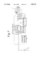
- FIG. 7 illustrates another example of the structure of a DC motor apparatus according to the present invention.
- FIG. 8 illustrates waveforms of the output of a position detector and of coil currents when a DC motor apparatus of the present invention is started.
- FIG. 9 illustrates still another example of the structure of a DC motor apparatus according to the present invention.
- FIG. 5 illustrates an operating principle of a DC motor according to the present invention.
- a current flows through coil 2 while permanent magnet 1 of the rotor is restricted, a magnetic attracting force is generated and permanent magnet 1 stays at a position where the above magnetic attracting force is balanced by a magnetic attracting force generated by the restricting magnetic field.
- permanent magnet 1 begins to return to the original restricted position taken before the current was supplied, but a repeated swing is generated due to inertial force of the rotor. While inertial force is produced in the rotational direction, a current is supplied again to coil 2, and the rotor swings more widely than previously.
- a rotating force T has a relationship with the inertial force expressed by the following equation to express motion:
- FIG. 6 and FIG. 7 respectively illustrate structures of different embodiments of a DC motor apparatus according to the present invention.
- a pulsating means 10 for pulsating currents flowing through coils 2 to 5 is disposed between position detector 7 and distributor 8.
- the reference numeral 11 designates a start detector that detects the completion of starting of the DC motor and outputs a signal for stopping or bypassing the operation of pulsating means 10.
- a current supplied from DC power supply 9 is supplied to coils 2 to 5 through pulsating means 10.
- position detector 7 detects the position of permanent magnet 1 and distributor 8 outputs a current to a desired one of coils 2 to 5. This current is controlled by pulsating means 10 and caused to flow intermittently. As a result, the inertial force works on the rotor incorporating permanent magnet 1 resulting in the excitation of the DC motor with a small current, as described above.
- detector 11 detects the completion of starting of the motor, detector 11 stops or bypasses operation of pulsating means 10.
- FIG. 8 illustrates waveforms of the output of position detector 7 and of currents flowing through coils 2 to 5 when the DC motor apparatus having the structure as shown in FIG. 6 and FIG. 7 is started.
- distributor 8 controlled by pulsating means 10 causes positive continuous currents to flow through coils 2 and 4 and negative continuous currents to flow through coils 3 and 5 at the same timing.
- the currents flowing through coils 2 to 5 are pulsated by pulsating means 10 at the time of starting the DC motor. After the motor has been started, currents similar to those in the prior art shown in FIG. 3 flow through coils 2 to 5.
- FIG. 9 illustrates another embodiment where a DC motor apparatus according to the present invention is driven by a solar cell array 12 as a power supply.
- start detector 11 is connected to an output terminal of solar cell array 12 so that a voltage appearing at this terminal drives pulsating means 10.
- solar cell array 12 accumulates a small current capacity. Therefore, a conventional DC motor apparatus as shown in FIG. 2 may not be able to be started.
- start detector 11 is connected to an output terminal of solar cell array 12.
- pulsating means 10 is activated to pulsate the currents fed from distributor 8 to the coils.
- the DC motor can be started with a small current.
- the output voltage of solar cell array 12 increases and pulsating means 10, automatically stops operation, resulting in a return to the stationary state.
- a DC motor for driving a pump may frequently start and stop depending on an amount of sunlight.
- the present invention can reduce a starting current by utilizing a structural characteristic of a DC motor enabling the provision of a DC motor apparatus with a simplified structure at low cost.
- the present invention is particularly suited for a DC motor apparatus in which a DC motor requiring a large starting current in comparison with a current in the stationary state is driven with a power supply having a small current capacity.
Landscapes
- Engineering & Computer Science (AREA)
- Power Engineering (AREA)
- Control Of Motors That Do Not Use Commutators (AREA)
Abstract
A DC motor apparatus which can be started with a power supply having a small current capacity and which provides a large driving force. The DC motor apparatus comprises a permanent magnet in a rotor of the DC motor, a plurality of coils provided at a stator of the DC motor, a distributor for controlling the switching of current paths to the coils and a position detector for detecting a rotational position of the rotor of the motor to output switching signal to the distributor. A pulsating unit is further provided for pulsating currents supplied to the coils whereby a current flowing from the distributor to any one of the coils can be pulsated when the DC motor is activated, resulting in easy starting the DC motor.
Description
This application is a Continuation of application Ser. No. 07/940,230, filed on Sep. 3, 1992, now abandoned.
1. Filed of the Invention
The present invention relates to a DC motor apparatus, and more particularly, to & DC motor which can be started with a small starting current.
2. Prior Art
In a conventional DC motor which requires a large driving force, a magnetic path is formed by a magnetic material section to enhance a magnetic flux density generated by a coil. A magnetic flux from a permanent magnet incorporated in a movable part of a motor converges in such a magnetic material section having high permeability. Therefore, since an intensive magnetic attracting force is generated between the permanent magnet and the magnetic material section it is necessary to supply a large exciting current from a power supply to such a DC motor.
FIG. 1 is a cross-sectional view indicating magnetic pole portions of a rotor and a stator of an ordinary DC motor. A permanent magnet 1 of the rotor has magnetic poles arranged alternately and coils 2 to 5 of the stator are formed around iron core 8. As explained above, since a magnetic flux generated from permanent magnet 1 converges in iron core 6 consisting of a magnetic material having a high permeability, an intensive magnetic attracting force is generated between iron core 6 and permanent magnet 1 and the rotor is restricted to stay in a constant direction. Therefore, it is necessary to generate a magnetic flux sufficient to overcome such restricting forces generated by other coils ( coils 2 and 4 in FIG. 1), in order to rotate the rotor.
FIG. 2 illustrates an example of an ordinary structure of a conventional DC motor apparatus. An output signal of position detector 7 for detecting a position of the permanent magnet of the rotor is supplied to distributor 8. Distributor 8 switches a current path to selectively supply a current from a DC power supply to any one of coils 2 to 5. When permanent magnet 1 begins to revolve, the current paths which supply currents to coils 2 to 5 are sequentially switched and the rotor of the motor comprising permanent magnet 1 rotates.
FIG. 3 illustrates waveforms of the output of position detector 7 in the DC apparatus shown in FIG. 2 and waveforms of currents flowing through coils 2 to 5. In the structure shown in FIG. 2, in the case where permanent magnet 1 of the rotor is rotating, outputs a and b of position detector 7 alternately go to a positive level periodically due to change in position of the magnetic poles of permanent magnet 1. When output a at a positive level and output b at a zero level are input to distributor 8, positive currents flow through coils 2 and 4 and negative currents flow through coils 3 and 5. Next, when the position of the magnetic poles change and outputs a and b supply signals at positive and zero levels, respectively, to distributor 8, negative currents flow through coils 2 and 4 and positive currents flow through coils 3 and 5. Thus, the switching of coils currents is repeated due to the switching of signals output from position detector 7.
In the conventional DC motor structured as illustrated in FIG. 1 and FIG. 2, an intensive magnetic attracting force is generated between iron core 6 and permanent magnet 1, and thus the rotor of the motor is restricted to stay in a constant direction. Therefore, a large current is required to start such a DC motor and DC power supply source 9 and distributor 8 are both required to have large current capacities. FIG. 4 illustrates waveforms of the output of position detector 7 and waveforms of currents flowing through coils 2 to 5 for start. In the structure shown in FIG. 2, when permanent magnet 1 of the rotor stops, if outputs a and b of position detector 7 are at positive and zero levels, respectively, distributor 8 receiving outputs a and b causes positive continuous currents to flow through coils 2 and 4 and negative continuous currents to flow through coils 3 and 5.
The present invention has been proposed considering the problems explained above. It is an object of the present invention to provide a DC motor apparatus which can solve the problems described above, namely, that can be started by means of a power supply source having a small current capacity and which provides a large driving force.
In order to achieve the object described above, a DC motor apparatus of the present invention comprises a rotor having a permanent magnet, a plurality of coils, a distributor for controlling switching of current paths to the coils and a position detector for detecting a rotational position of the rotor of the motor to output a switching signal to the distributor. The DC motor apparatus further comprises a pulsating means (pulse forming means) for pulsating a current flowing through any one of the coils. This pulsating means pulsates the current supplied to the coils by the distributor at the time of starting the DC motor.
As described above, a pulsating means is provided and the currents supplied to the coils by the distributor are pulsated by the pulsating means at the time of starting the DC motor. Consequently, magnetic attracting force repeatedly increases or decreases in any rotational direction forcing the rotor to swing back and forth around the restricted position. As a result, a rotating force is increased and the DC motor can be started with only a low level current.
FIG. 1 is a cross-sectional view illustrating magnetic pole pot%ions of a rotor and a stator of an ordinary DC motor;
FIG. 2 illustrates an example of an ordinary structure of a conventional DC motor apparatus;
FIG. 3 illustrates waveforms of the output of a position detector and of coil currents after a DC motor apparatus is started;
FIG. 4 illustrates waveforms of the output of the position detector and of coil currents when the DC motor apparatus shown in FIG. 2 is started;
FIG. 5 is a diagram for explaining an operational principle of a DC motor according to the present invention;
FIG. 6 illustrates an example of the structure of a DC motor apparatus according to the present invention;
FIG. 7 illustrates another example of the structure of a DC motor apparatus according to the present invention;
FIG. 8 illustrates waveforms of the output of a position detector and of coil currents when a DC motor apparatus of the present invention is started; and
FIG. 9 illustrates still another example of the structure of a DC motor apparatus according to the present invention.
Embodiments of the present invention will be described with reference to the accompanying drawings. Elements the same as those shown in FIG. 1 and FIG. 2 are denoted by like reference numbers. The principle of the present invention will be described first. FIG. 5 illustrates an operating principle of a DC motor according to the present invention. In FIG. 5, when a current flows through coil 2 while permanent magnet 1 of the rotor is restricted, a magnetic attracting force is generated and permanent magnet 1 stays at a position where the above magnetic attracting force is balanced by a magnetic attracting force generated by the restricting magnetic field. Thereafter, when the current flowing through coil 2 is cut off, permanent magnet 1 begins to return to the original restricted position taken before the current was supplied, but a repeated swing is generated due to inertial force of the rotor. While inertial force is produced in the rotational direction, a current is supplied again to coil 2, and the rotor swings more widely than previously.
A rotating force T has a relationship with the inertial force expressed by the following equation to express motion:
T=J(d.sup.2 θ/dt.sup.2)+D(dθ/dt)kθ
Where,
J: inertial force;
D: control factor;
k: spring constant;
θ: rotating angle.
When a current is initially supplied to the coil, no inertial force is generated because of the stationary condition. However, when a current is supplied again after the current has been cut off, rotating force T increases when force J is of a positive value resulting in an increase in rotating angle θ. Therefore, the rotating force can be caused to increase by controlling a coil current flow when the inertial force is applied in the rotating direction, and thus the DC motor can be started with only a small current. An example of the structure of a DC motor according to the present invention utilizing such an operational principle as described above will be explained hereunder.
FIG. 6 and FIG. 7 respectively illustrate structures of different embodiments of a DC motor apparatus according to the present invention. In FIG. 6, a pulsating means 10 for pulsating currents flowing through coils 2 to 5 is disposed between position detector 7 and distributor 8. The reference numeral 11 designates a start detector that detects the completion of starting of the DC motor and outputs a signal for stopping or bypassing the operation of pulsating means 10. In FIG. 7, a current supplied from DC power supply 9 is supplied to coils 2 to 5 through pulsating means 10.
In the DC motor apparatus having the structure as shown in FIG. 6 and FIG. 7, position detector 7 detects the position of permanent magnet 1 and distributor 8 outputs a current to a desired one of coils 2 to 5. This current is controlled by pulsating means 10 and caused to flow intermittently. As a result, the inertial force works on the rotor incorporating permanent magnet 1 resulting in the excitation of the DC motor with a small current, as described above. When detector 11 detects the completion of starting of the motor, detector 11 stops or bypasses operation of pulsating means 10.
FIG. 8 illustrates waveforms of the output of position detector 7 and of currents flowing through coils 2 to 5 when the DC motor apparatus having the structure as shown in FIG. 6 and FIG. 7 is started. In the structure shown in FIG. 6, when permanent magnet 1 of the rotor stops, if outputs a and b of position detector 7 are at positive and zero levels, respectively, distributor 8 controlled by pulsating means 10 causes positive continuous currents to flow through coils 2 and 4 and negative continuous currents to flow through coils 3 and 5 at the same timing. As illustrated in the figures, the currents flowing through coils 2 to 5 are pulsated by pulsating means 10 at the time of starting the DC motor. After the motor has been started, currents similar to those in the prior art shown in FIG. 3 flow through coils 2 to 5.
There is no substantial difference in effect of pulsating currents flowing through coils 2 to 5 in the example (refer to FIG. 6) where pulsating means 10 is disposed between position detector 7 and distributor 8 and in the example (refer to FIG. 7) where pulsating means 10 is disposed between DC power supply 9 and coils 2 to 5.
FIG. 9 illustrates another embodiment where a DC motor apparatus according to the present invention is driven by a solar cell array 12 as a power supply. As indicated in the figure, start detector 11 is connected to an output terminal of solar cell array 12 so that a voltage appearing at this terminal drives pulsating means 10. After only limited exposure to sunlight, solar cell array 12 accumulates a small current capacity. Therefore, a conventional DC motor apparatus as shown in FIG. 2 may not be able to be started. In order to avoid such a problem, start detector 11 is connected to an output terminal of solar cell array 12. When the voltage at the output terminal is lower than a predetermined value, pulsating means 10 is activated to pulsate the currents fed from distributor 8 to the coils. As a result, the DC motor can be started with a small current. When an amount of sunlight increases, the output voltage of solar cell array 12 increases and pulsating means 10, automatically stops operation, resulting in a return to the stationary state. Particularly, when it is requested to start a pump with a solar cell array, a DC motor for driving a pump may frequently start and stop depending on an amount of sunlight. Such a problem can effectively be solved by using a DC motor apparatus according to the present invention.
As described above, the present invention can reduce a starting current by utilizing a structural characteristic of a DC motor enabling the provision of a DC motor apparatus with a simplified structure at low cost. The present invention is particularly suited for a DC motor apparatus in which a DC motor requiring a large starting current in comparison with a current in the stationary state is driven with a power supply having a small current capacity.
While the present invention has been described in detail with reference to specific embodiments thereof, it will be understood by those skilled in the art that various changes and modifications may be made without departing from the spirit and scope of the invention claimed.
Claims (6)
1. A DC motor comprising:
a rotary member for rotating about an axis;
a stationary member having a pluarlity of coils;
a position setecting means for detecting a pluarlity of positions of said rotary member as said rotary member rotates about said axis;
a DC current distributing means responsive to the output of said position detecting means for sequentially swithcing DC current supplied to said plurality of coils;
a pulsating means for pulsating the DC current flowing through at least one of said plurality of coils selected on the basis of a position of said rotary member detected by said position detector during a period that said DC current is being supplied to said at least one coil; and
wherein, during start-up of the motor, the DC current is pulsed in a timed sequence such that a driving force due to the DC current coincides with a back-and-forth swing of the rotary member resulting from the inertial force of the rotary member when the DC current pulses are supplied thereto.
2. A DC motor apparatus according to claim 1, wherein said pulsating means is disposed between said position detecting means and said distributing means.
3. A DC motor apparatus according to claim 2, further comprising an excitation;detector for detecting the completion of starting of said motor to stop or bypass the operation of said pulsating means.
4. A DC motor apparatus according to claim 1, wherein said pulsating means is disposed between said plurality of coils and a power supply which supplies currents to these coils.
5. A DC motor apparatus according to claim 4, further comprising an excitation detector for detecting the completion of starting of said motor to stop or bypass the operation of said pulsating means.
6. A DC motor comprising:
a magnetic rotor being rotatable about an axis;
a stator adjacent said rotor and having a plurality of coils;
a position detecting means for detecting a magnetic position of the rotor with respect to the stator;
a DC current distributor connectable to the coils for supplying current and creating magnetic fields around the coils for causing the rotor to rotate;
a pulsating unit for pulsating the current supplied by the distributor;
a detector for detecting when the DC motor is in an initial start-up state and when the DC motor reaches a steady-state;
wherein, during the initial start-up state of the DC motor, current is supplied to a single coil selected on the basis of the magnetic position of the rotor, the pulsating unit pulsates the current supplied to said single coil at a rate which causes the rotor to pendulate back and forth with increasing momentum; and
wherein, during the steady-state of the DC motor, the pulsating unit no longer pulsates the current and the DC distributor supplies current to each of the coils in sequential order to cause the rotor to continuously rotate.
Priority Applications (1)
| Application Number | Priority Date | Filing Date | Title |
|---|---|---|---|
| US08/183,775 US5486742A (en) | 1991-09-17 | 1994-01-21 | Easily started DC motor apparatus |
Applications Claiming Priority (4)
| Application Number | Priority Date | Filing Date | Title |
|---|---|---|---|
| JP3-265250 | 1991-09-17 | ||
| JP3265250A JPH0583981A (en) | 1991-09-17 | 1991-09-17 | Dc motor unit |
| US94023092A | 1992-09-03 | 1992-09-03 | |
| US08/183,775 US5486742A (en) | 1991-09-17 | 1994-01-21 | Easily started DC motor apparatus |
Related Parent Applications (1)
| Application Number | Title | Priority Date | Filing Date |
|---|---|---|---|
| US94023092A Continuation | 1991-09-17 | 1992-09-03 |
Publications (1)
| Publication Number | Publication Date |
|---|---|
| US5486742A true US5486742A (en) | 1996-01-23 |
Family
ID=17414621
Family Applications (1)
| Application Number | Title | Priority Date | Filing Date |
|---|---|---|---|
| US08/183,775 Expired - Fee Related US5486742A (en) | 1991-09-17 | 1994-01-21 | Easily started DC motor apparatus |
Country Status (6)
| Country | Link |
|---|---|
| US (1) | US5486742A (en) |
| EP (1) | EP0533061B1 (en) |
| JP (1) | JPH0583981A (en) |
| AU (1) | AU657562B2 (en) |
| DE (1) | DE69229027T2 (en) |
| DK (1) | DK0533061T3 (en) |
Cited By (3)
| Publication number | Priority date | Publication date | Assignee | Title |
|---|---|---|---|---|
| US6078152A (en) * | 1996-01-10 | 2000-06-20 | Papst-Motoren Gmbh & Co. Kg | Bidirectional E.C. motor and method of operating the motor |
| US6281616B1 (en) | 1997-07-24 | 2001-08-28 | Papst-Motoren Gmbh & Co. Kg | Claw pole motor |
| US20080315873A1 (en) * | 2007-06-19 | 2008-12-25 | Schlumberger Technology Corporation | Method and Apparatus for Measuring Free Induction Decay Signal and Its Application to Composition Analysis |
Citations (34)
| Publication number | Priority date | Publication date | Assignee | Title |
|---|---|---|---|---|
| US3609492A (en) * | 1970-07-17 | 1971-09-28 | Sperry Rand Corp | Reversible brushless dc motor |
| US3831073A (en) * | 1972-04-28 | 1974-08-20 | Canon Kk | Control system for synchronous drive of dc motor |
| US3922590A (en) * | 1972-04-20 | 1975-11-25 | Mettoy Co Ltd | Electrical systems and apparatus |
| US3997823A (en) * | 1973-10-30 | 1976-12-14 | Sony Corporation | Brushless DC motor driving circuit |
| US4027213A (en) * | 1974-03-28 | 1977-05-31 | Valroger Pierre Albert Marie D | Electronic switching arrangement for energizing electric motors |
| GB2020915A (en) * | 1978-05-08 | 1979-11-21 | Kollmorgen Tech Corp | Brushless dc motor printed circuit armature |
| US4205260A (en) * | 1977-06-30 | 1980-05-27 | Matsushita Electric Industrial Co., Ltd. | Motor control system |
| US4251758A (en) * | 1979-02-15 | 1981-02-17 | Danfoss A/S | Control circuit for a self-starting electric motor |
| AU8193882A (en) * | 1976-10-05 | 1982-07-15 | General Electric Company | Electronically commutated motor |
| EP0072597A2 (en) * | 1981-08-17 | 1983-02-23 | Koninklijke Philips Electronics N.V. | Self-starting brushless D.C. motor |
| US4418303A (en) * | 1981-03-30 | 1983-11-29 | Sony Corporation | DC Motor control circuit |
| US4449079A (en) * | 1980-04-17 | 1984-05-15 | General Electric Company | Control system for an electronically commutated motor |
| US4454458A (en) * | 1981-12-02 | 1984-06-12 | Hewlett-Packard Company | Synchronous drive for brushless DC motor |
| US4492903A (en) * | 1977-05-23 | 1985-01-08 | Nu-Tech Industries, Inc. | Optimum efficiency brushless DC motor |
| JPS60100822A (en) * | 1983-11-07 | 1985-06-04 | Nippon Telegr & Teleph Corp <Ntt> | Semiconductor switch circuit |
| JPS61165051A (en) * | 1984-09-28 | 1986-07-25 | レイランド ビ−クルズ リミテツド | Continuous speed change gearing |
| JPS61258696A (en) * | 1985-05-08 | 1986-11-17 | Matsushita Electric Ind Co Ltd | Starting device for magnet rotating motor |
| US4642539A (en) * | 1985-06-10 | 1987-02-10 | Northern Magnetics, Inc. | Torque motor with unlimited angular excursion |
| JPS6265116A (en) * | 1985-09-17 | 1987-03-24 | Toshiba Corp | Photovoltaic power generating set |
| US4658192A (en) * | 1986-01-31 | 1987-04-14 | General Electric Company | Programmable deadband current regulator |
| JPS6298410A (en) * | 1985-10-25 | 1987-05-07 | Toshiba Corp | Solar light generating set |
| JPS62118785A (en) * | 1985-11-19 | 1987-05-30 | Matsushita Seiko Co Ltd | Starter for commutatorless motor |
| US4678973A (en) * | 1986-10-07 | 1987-07-07 | General Motors Corporation | Sensorless starting control for a brushless DC motor |
| US4706005A (en) * | 1985-04-09 | 1987-11-10 | Citizen Watch Co., Ltd. | Control circuit of direct current servomotor for floppy disk drive |
| US4713544A (en) * | 1984-03-05 | 1987-12-15 | Siemens Aktiengesellschaft | Optical system for the simultaneous reception of thermal and laser radiation |
| US4713594A (en) * | 1986-10-03 | 1987-12-15 | General Electric Company | Start-up control for switched reluctance motor |
| US4763347A (en) * | 1983-02-02 | 1988-08-09 | General Electric Company | Control system, electronically commutated motor system, blower apparatus and methods |
| EP0316077A1 (en) * | 1987-10-31 | 1989-05-17 | Sony Corporation | Brushless motors |
| WO1989011523A2 (en) * | 1988-05-25 | 1989-11-30 | Piper, James, William | Rotor position sensing |
| US4959599A (en) * | 1985-05-22 | 1990-09-25 | Fuji Photo Film Co., Ltd. | Head positioner |
| US4999560A (en) * | 1985-06-11 | 1991-03-12 | Kabushiki Kaisha Toshiba | Electric motor running system employing photovoltaic array |
| US5023527A (en) * | 1974-06-24 | 1991-06-11 | General Electric Company | Control circuits, electronically commutated motor systems and methods |
| US5068582A (en) * | 1990-05-29 | 1991-11-26 | A. O. Smith Corporation | Brushless pulsed D.C. motor |
| US5235264A (en) * | 1990-06-30 | 1993-08-10 | Nippon Densan Corporation | Method of and circuit for starting sensorless motor |
Family Cites Families (1)
| Publication number | Priority date | Publication date | Assignee | Title |
|---|---|---|---|---|
| JPH0265689A (en) * | 1988-08-29 | 1990-03-06 | Tokyo Electric Co Ltd | brushless motor |
-
1991
- 1991-09-17 JP JP3265250A patent/JPH0583981A/en active Pending
-
1992
- 1992-09-08 AU AU22198/92A patent/AU657562B2/en not_active Ceased
- 1992-09-10 EP EP92115539A patent/EP0533061B1/en not_active Revoked
- 1992-09-10 DK DK92115539T patent/DK0533061T3/en active
- 1992-09-10 DE DE69229027T patent/DE69229027T2/en not_active Expired - Fee Related
-
1994
- 1994-01-21 US US08/183,775 patent/US5486742A/en not_active Expired - Fee Related
Patent Citations (35)
| Publication number | Priority date | Publication date | Assignee | Title |
|---|---|---|---|---|
| US3609492A (en) * | 1970-07-17 | 1971-09-28 | Sperry Rand Corp | Reversible brushless dc motor |
| US3922590A (en) * | 1972-04-20 | 1975-11-25 | Mettoy Co Ltd | Electrical systems and apparatus |
| US3831073A (en) * | 1972-04-28 | 1974-08-20 | Canon Kk | Control system for synchronous drive of dc motor |
| US3997823A (en) * | 1973-10-30 | 1976-12-14 | Sony Corporation | Brushless DC motor driving circuit |
| US4027213A (en) * | 1974-03-28 | 1977-05-31 | Valroger Pierre Albert Marie D | Electronic switching arrangement for energizing electric motors |
| US5023527A (en) * | 1974-06-24 | 1991-06-11 | General Electric Company | Control circuits, electronically commutated motor systems and methods |
| AU8193882A (en) * | 1976-10-05 | 1982-07-15 | General Electric Company | Electronically commutated motor |
| US4492903A (en) * | 1977-05-23 | 1985-01-08 | Nu-Tech Industries, Inc. | Optimum efficiency brushless DC motor |
| US4205260A (en) * | 1977-06-30 | 1980-05-27 | Matsushita Electric Industrial Co., Ltd. | Motor control system |
| GB2020915A (en) * | 1978-05-08 | 1979-11-21 | Kollmorgen Tech Corp | Brushless dc motor printed circuit armature |
| US4251758A (en) * | 1979-02-15 | 1981-02-17 | Danfoss A/S | Control circuit for a self-starting electric motor |
| US4449079A (en) * | 1980-04-17 | 1984-05-15 | General Electric Company | Control system for an electronically commutated motor |
| US4418303A (en) * | 1981-03-30 | 1983-11-29 | Sony Corporation | DC Motor control circuit |
| EP0072597A2 (en) * | 1981-08-17 | 1983-02-23 | Koninklijke Philips Electronics N.V. | Self-starting brushless D.C. motor |
| US4814676A (en) * | 1981-08-17 | 1989-03-21 | U.S. Philips Corporation | Self-starting brushless D.C. motor |
| US4454458A (en) * | 1981-12-02 | 1984-06-12 | Hewlett-Packard Company | Synchronous drive for brushless DC motor |
| US4763347A (en) * | 1983-02-02 | 1988-08-09 | General Electric Company | Control system, electronically commutated motor system, blower apparatus and methods |
| JPS60100822A (en) * | 1983-11-07 | 1985-06-04 | Nippon Telegr & Teleph Corp <Ntt> | Semiconductor switch circuit |
| US4713544A (en) * | 1984-03-05 | 1987-12-15 | Siemens Aktiengesellschaft | Optical system for the simultaneous reception of thermal and laser radiation |
| JPS61165051A (en) * | 1984-09-28 | 1986-07-25 | レイランド ビ−クルズ リミテツド | Continuous speed change gearing |
| US4706005A (en) * | 1985-04-09 | 1987-11-10 | Citizen Watch Co., Ltd. | Control circuit of direct current servomotor for floppy disk drive |
| JPS61258696A (en) * | 1985-05-08 | 1986-11-17 | Matsushita Electric Ind Co Ltd | Starting device for magnet rotating motor |
| US4959599A (en) * | 1985-05-22 | 1990-09-25 | Fuji Photo Film Co., Ltd. | Head positioner |
| US4642539A (en) * | 1985-06-10 | 1987-02-10 | Northern Magnetics, Inc. | Torque motor with unlimited angular excursion |
| US4999560A (en) * | 1985-06-11 | 1991-03-12 | Kabushiki Kaisha Toshiba | Electric motor running system employing photovoltaic array |
| JPS6265116A (en) * | 1985-09-17 | 1987-03-24 | Toshiba Corp | Photovoltaic power generating set |
| JPS6298410A (en) * | 1985-10-25 | 1987-05-07 | Toshiba Corp | Solar light generating set |
| JPS62118785A (en) * | 1985-11-19 | 1987-05-30 | Matsushita Seiko Co Ltd | Starter for commutatorless motor |
| US4658192A (en) * | 1986-01-31 | 1987-04-14 | General Electric Company | Programmable deadband current regulator |
| US4713594A (en) * | 1986-10-03 | 1987-12-15 | General Electric Company | Start-up control for switched reluctance motor |
| US4678973A (en) * | 1986-10-07 | 1987-07-07 | General Motors Corporation | Sensorless starting control for a brushless DC motor |
| EP0316077A1 (en) * | 1987-10-31 | 1989-05-17 | Sony Corporation | Brushless motors |
| WO1989011523A2 (en) * | 1988-05-25 | 1989-11-30 | Piper, James, William | Rotor position sensing |
| US5068582A (en) * | 1990-05-29 | 1991-11-26 | A. O. Smith Corporation | Brushless pulsed D.C. motor |
| US5235264A (en) * | 1990-06-30 | 1993-08-10 | Nippon Densan Corporation | Method of and circuit for starting sensorless motor |
Non-Patent Citations (4)
| Title |
|---|
| Patent Abstracts of Japan, vol. 11, No. 110, (E 496) 2557 , Apr. 7, 1987, & JP A 61 258696, Nov. 17, 1986, Masaki Takahashi, et al., Starter of Magnet Rotary Type Motor . * |
| Patent Abstracts of Japan, vol. 11, No. 110, (E-496)[2557], Apr. 7, 1987, & JP-A-61-258696, Nov. 17, 1986, Masaki Takahashi, et al., "Starter of Magnet Rotary Type Motor". |
| Patent Abstracts of Japan, vol. 11, No. 338, (E 553) 2785 , Nov. 5, 1987, & JP A 62 118785, May 30, 1987, Kanji Izaki, et al., Starter for Commutatorless Motor . * |
| Patent Abstracts of Japan, vol. 11, No. 338, (E-553)[2785], Nov. 5, 1987, & JP-A-62-118785, May 30, 1987, Kanji Izaki, et al., "Starter for Commutatorless Motor". |
Cited By (4)
| Publication number | Priority date | Publication date | Assignee | Title |
|---|---|---|---|---|
| US6078152A (en) * | 1996-01-10 | 2000-06-20 | Papst-Motoren Gmbh & Co. Kg | Bidirectional E.C. motor and method of operating the motor |
| US6281616B1 (en) | 1997-07-24 | 2001-08-28 | Papst-Motoren Gmbh & Co. Kg | Claw pole motor |
| US20080315873A1 (en) * | 2007-06-19 | 2008-12-25 | Schlumberger Technology Corporation | Method and Apparatus for Measuring Free Induction Decay Signal and Its Application to Composition Analysis |
| US7564240B2 (en) | 2007-06-19 | 2009-07-21 | Schlumberger Technology Corporation | Method and apparatus for measuring free induction decay signal and its application to composition analysis |
Also Published As
| Publication number | Publication date |
|---|---|
| JPH0583981A (en) | 1993-04-02 |
| EP0533061B1 (en) | 1999-04-28 |
| DE69229027T2 (en) | 1999-11-25 |
| AU657562B2 (en) | 1995-03-16 |
| DE69229027D1 (en) | 1999-06-02 |
| EP0533061A1 (en) | 1993-03-24 |
| DK0533061T3 (en) | 1999-11-08 |
| AU2219892A (en) | 1993-03-18 |
Similar Documents
| Publication | Publication Date | Title |
|---|---|---|
| JP3432226B2 (en) | Pulse width modulation motor controller | |
| US5783916A (en) | Apparatus and method for generating rotor position signals and controlling commutation in a variable reluctance electric motor | |
| CA2387158A1 (en) | For driving step motors without overshoot | |
| EP0765027B1 (en) | Noise reduction in a switched reluctance motor by current profile | |
| US5530332A (en) | Stepper motor drive circuit | |
| US5124606A (en) | Dual rotor with continuous/positioning reverse controls | |
| EA011737B1 (en) | Electric motor | |
| US5537019A (en) | Switched reluctance motor providing rotor position detection at high speeds without a separate rotor shaft position sensor | |
| US5225758A (en) | Apparatus for driving a variable reluctance motor | |
| KR920015689A (en) | Drive circuit of brushless motor | |
| US5486742A (en) | Easily started DC motor apparatus | |
| JPS5843200A (en) | Exciting system for step motor | |
| KR100279185B1 (en) | Drive control device of brushless motor | |
| US5760565A (en) | Method and apparatus for reducing iron losses in a switched reluctance machine | |
| JPS60204292A (en) | Drive device for motor | |
| US4746847A (en) | Control system for a stepping motor | |
| US5729112A (en) | Phase current sensing in a bifilar-wound switched reluctance motor drive topology | |
| JPS6188784A (en) | Controller of brushless motor | |
| JPS62233096A (en) | Driving system for stepping motor | |
| JP3089025B2 (en) | Control method and control device for stepping motor | |
| Cooke | Stepper motors: Principles and characteristics | |
| WO1997034365A1 (en) | System for controlling operation of a switched reluctance motor between a multi-phase operating mode and a reduced phase operating mode | |
| JP2002199769A (en) | Drive method for switched reluctance motor | |
| JP2931164B2 (en) | Drive circuit for brushless motor | |
| JPH04173000A (en) | Driving circuit for stepping motor |
Legal Events
| Date | Code | Title | Description |
|---|---|---|---|
| FPAY | Fee payment |
Year of fee payment: 4 |
|
| REMI | Maintenance fee reminder mailed | ||
| LAPS | Lapse for failure to pay maintenance fees | ||
| FP | Lapsed due to failure to pay maintenance fee |
Effective date: 20040123 |
|
| STCH | Information on status: patent discontinuation |
Free format text: PATENT EXPIRED DUE TO NONPAYMENT OF MAINTENANCE FEES UNDER 37 CFR 1.362 |