US5484102A - Folding carton blank with feed gate engaging notch - Google Patents
Folding carton blank with feed gate engaging notch Download PDFInfo
- Publication number
- US5484102A US5484102A US08/198,993 US19899394A US5484102A US 5484102 A US5484102 A US 5484102A US 19899394 A US19899394 A US 19899394A US 5484102 A US5484102 A US 5484102A
- Authority
- US
- United States
- Prior art keywords
- panel end
- end flap
- blank
- folded
- hingedly connected
- Prior art date
- Legal status (The legal status is an assumption and is not a legal conclusion. Google has not performed a legal analysis and makes no representation as to the accuracy of the status listed.)
- Expired - Lifetime
Links
- 239000011087 paperboard Substances 0.000 abstract description 23
- 239000000853 adhesive Substances 0.000 description 14
- 230000001070 adhesive effect Effects 0.000 description 14
- 239000012528 membrane Substances 0.000 description 12
- 239000003292 glue Substances 0.000 description 7
- 239000000976 ink Substances 0.000 description 6
- 238000000034 method Methods 0.000 description 6
- 238000005520 cutting process Methods 0.000 description 4
- 239000002184 metal Substances 0.000 description 4
- 238000004806 packaging method and process Methods 0.000 description 4
- 239000000047 product Substances 0.000 description 4
- 239000007787 solid Substances 0.000 description 3
- 230000009471 action Effects 0.000 description 1
- 238000007792 addition Methods 0.000 description 1
- 230000004075 alteration Effects 0.000 description 1
- 238000010420 art technique Methods 0.000 description 1
- 235000009508 confectionery Nutrition 0.000 description 1
- 238000000151 deposition Methods 0.000 description 1
- 235000015243 ice cream Nutrition 0.000 description 1
- 238000004519 manufacturing process Methods 0.000 description 1
- 238000012986 modification Methods 0.000 description 1
- 230000004048 modification Effects 0.000 description 1
- 239000005022 packaging material Substances 0.000 description 1
- 230000008569 process Effects 0.000 description 1
- 239000002994 raw material Substances 0.000 description 1
- 238000007789 sealing Methods 0.000 description 1
- 238000000926 separation method Methods 0.000 description 1
- 235000011888 snacks Nutrition 0.000 description 1
- 239000012265 solid product Substances 0.000 description 1
Images


Classifications
-
- B—PERFORMING OPERATIONS; TRANSPORTING
- B65—CONVEYING; PACKING; STORING; HANDLING THIN OR FILAMENTARY MATERIAL
- B65D—CONTAINERS FOR STORAGE OR TRANSPORT OF ARTICLES OR MATERIALS, e.g. BAGS, BARRELS, BOTTLES, BOXES, CANS, CARTONS, CRATES, DRUMS, JARS, TANKS, HOPPERS, FORWARDING CONTAINERS; ACCESSORIES, CLOSURES, OR FITTINGS THEREFOR; PACKAGING ELEMENTS; PACKAGES
- B65D5/00—Rigid or semi-rigid containers of polygonal cross-section, e.g. boxes, cartons or trays, formed by folding or erecting one or more blanks made of paper
- B65D5/42—Details of containers or of foldable or erectable container blanks
- B65D5/54—Lines of weakness to facilitate opening of container or dividing it into separate parts by cutting or tearing
- B65D5/5405—Lines of weakness to facilitate opening of container or dividing it into separate parts by cutting or tearing for opening containers formed by erecting a blank in tubular form
- B65D5/5415—Lines of weakness to facilitate opening of container or dividing it into separate parts by cutting or tearing for opening containers formed by erecting a blank in tubular form the lines of weakness being provided in one or more closure flaps and in the container body so as to form after rupture a lid hinged to a side edge of the container body
-
- Y—GENERAL TAGGING OF NEW TECHNOLOGICAL DEVELOPMENTS; GENERAL TAGGING OF CROSS-SECTIONAL TECHNOLOGIES SPANNING OVER SEVERAL SECTIONS OF THE IPC; TECHNICAL SUBJECTS COVERED BY FORMER USPC CROSS-REFERENCE ART COLLECTIONS [XRACs] AND DIGESTS
- Y10—TECHNICAL SUBJECTS COVERED BY FORMER USPC
- Y10S—TECHNICAL SUBJECTS COVERED BY FORMER USPC CROSS-REFERENCE ART COLLECTIONS [XRACs] AND DIGESTS
- Y10S229/00—Envelopes, wrappers, and paperboard boxes
- Y10S229/90—Envelopes, wrappers, and paperboard boxes including means to facilitate handling by a mechanical apparatus during manufacturing or filling
-
- Y—GENERAL TAGGING OF NEW TECHNOLOGICAL DEVELOPMENTS; GENERAL TAGGING OF CROSS-SECTIONAL TECHNOLOGIES SPANNING OVER SEVERAL SECTIONS OF THE IPC; TECHNICAL SUBJECTS COVERED BY FORMER USPC CROSS-REFERENCE ART COLLECTIONS [XRACs] AND DIGESTS
- Y10—TECHNICAL SUBJECTS COVERED BY FORMER USPC
- Y10S—TECHNICAL SUBJECTS COVERED BY FORMER USPC CROSS-REFERENCE ART COLLECTIONS [XRACs] AND DIGESTS
- Y10S229/00—Envelopes, wrappers, and paperboard boxes
- Y10S229/902—Box for prepared or processed food
- Y10S229/905—Frozen food
-
- Y—GENERAL TAGGING OF NEW TECHNOLOGICAL DEVELOPMENTS; GENERAL TAGGING OF CROSS-SECTIONAL TECHNOLOGIES SPANNING OVER SEVERAL SECTIONS OF THE IPC; TECHNICAL SUBJECTS COVERED BY FORMER USPC CROSS-REFERENCE ART COLLECTIONS [XRACs] AND DIGESTS
- Y10—TECHNICAL SUBJECTS COVERED BY FORMER USPC
- Y10S—TECHNICAL SUBJECTS COVERED BY FORMER USPC CROSS-REFERENCE ART COLLECTIONS [XRACs] AND DIGESTS
- Y10S229/00—Envelopes, wrappers, and paperboard boxes
- Y10S229/93—Fold detail
-
- Y—GENERAL TAGGING OF NEW TECHNOLOGICAL DEVELOPMENTS; GENERAL TAGGING OF CROSS-SECTIONAL TECHNOLOGIES SPANNING OVER SEVERAL SECTIONS OF THE IPC; TECHNICAL SUBJECTS COVERED BY FORMER USPC CROSS-REFERENCE ART COLLECTIONS [XRACs] AND DIGESTS
- Y10—TECHNICAL SUBJECTS COVERED BY FORMER USPC
- Y10S—TECHNICAL SUBJECTS COVERED BY FORMER USPC CROSS-REFERENCE ART COLLECTIONS [XRACs] AND DIGESTS
- Y10S229/00—Envelopes, wrappers, and paperboard boxes
- Y10S229/933—Mating container blanks
- Y10S229/935—No waste, i.e. edge-to-edge blanks
Definitions
- the present invention generally relates to folding paperboard cartons and, more particularly, to an improved carton blank which eliminates ink-smearing problems during finishing operations.
- Folding cartons are well known in the packaging art. These cartons are constructed from flat blanks which are pre-cut and pre-scored on paperboard sheets. Carton blanks have four main panels which are adapted to form the top, rear, bottom and front of an assembled carton. Each panel has a pair of end flaps which are hingedly connected by score lines formed in the paperboard.
- the blanks are folded once and secured with known adhesives to form carton sleeves which are used for packaging retail products, typically consumable goods.
- packaging machinery is used to form and seal fully assembled cartons according to a prescribed folding sequence and adhesive pattern.
- U.S. Pat. No. 4,712,730 describes a state-of-the-art carton blank used to assemble a rectangular, top opening carton. First and second ends of the carton are closed by folding the bottom panel end flaps first; front panel end flaps second; top panel end flaps third and rear panel end flaps fourth.
- first-folded bottom panel end flaps are spatially removed from fourth-folded rear panel end flaps by intervening front and top panel end flaps. This spatial separation is generally characterized by a single or double thickness of paperboard stock.
- U.S. Pat. No. 4,872,609 addresses this problem by describing raised portions formed in the bottom panel end flaps of a typical carton blank. These raised portions are substantially triangular in shape and operably associated with cutouts formed in the front panel end flaps of an assembled carton. According to this disclosure, the end wall-forming flaps are substantially co-planar so that fourth-folded rear panel end flaps are securely fastened to first-folded bottom panel end flaps with known adhesive patterns.
- the offset portions of the prior art are raised from the bottom panel end flaps of a carton blank. They are formed in the paperboard stock by stamping the carton blanks in an upward, opposite direction with reference to the score lines and perforations. This procedure involves a reverse die-stamping operation which requires special make ready procedures and additional expense.
- Carton blanks are produced from large paperboard sheets in a multiple configuration. Individual blanks are internally "nested” on three sides to minimize the amount of wasted paperboard. During the blanking operation, score lines are provided to facilitate the flap-folding sequence. Perforations are also cut in the paperboard to form art-recognized tear-away and breakaway features like those described in U.S. Pat. No. 4,712,689. Perforations and score lines are formed by die-cutting and die-stamping the carton blanks in a single, downward direction.
- Adjacent blanks are frequently printed with different inks specified by various customers.
- a bleed line is used to extend the ink from one blank onto an adjacent blank in areas that are not shown by a squared-up carton.
- single stacks of cut, printed blanks enter finishing machines through a feed gate which uses the bleed line as the initial point of contact. This operation causes smearing of ink from the bleed lines as blanks pass through the feed gate.
- Feed gate openings are typically adjusted to a single thickness of paperboard (approximately 1/24,000 of an inch) to create a controlled entry point for one carton blank at a time. As the lowest blank in the stack passes enters the finishing equipment, bleed line ink is smeared by the action of the feed gate and the aggregate weight of the overlying blanks.
- the present invention eliminates this problem with an engaging notch formed on at least one main panel end flap of the carton blank.
- Another object of the present invention is to provide a simplified carton blank with improved machinability characteristics.
- Another object of the present invention is to provide a carton blank with a feed gate engaging notch formed on at least one main panel end flap.
- a further object of the present invention is to provide a carton blank which eliminates ink smearing during the finishing operation.
- the presently claimed invention is directed to a novel blank for assembling folding cartons, comprising bottom, front, top and rear panels.
- Each main panel has a left end flap and a right end flap.
- Score lines are disposed between the main panels and their respective end flaps.
- the top panel has score lines which define second and third fold lines which hingedly connect the left and right top end flaps, respectively.
- the blank defined in the claims forms a carton which is closed by folding the end flaps according to a specific sequence bottom (1), front (2), top (3) and rear (4).
- the left and right bottom end flaps each have a free edge which engage the second and third fold lines of the top panel, respectively.
- the left and right front end flaps each have a free edge which also engage the second and third fold lines of the top panel, respectively.
- the front, bottom, rear and top panels, hingedly connected by score lines, are adapted to form a corresponding sleeve which is readily converted into an open-ended carton, closed at one end, filled with a selected product and closed at the other end in a manner well-known in the art.
- Optional lips or membranes are hingedly connected to the top edge of the front panel and front panel end flaps of the carton blank.
- the blank also includes a cover panel portion hingedly connected to the top panel and adapted to overlap the front panel.
- a releasable tear strip is formed in the cover panel portion by perforations in the paperboard stock.
- Breakaway features may be formed in the rear panel end flaps to facilitate positive reclosure of an assembled carton during end-use application. Offset portions may be formed by die-stampings in the rear panel end flaps. When the flap-folding sequence is accomplished, these offset portions contact the bottom panel end flaps to provide adhesively secured end walls in an assembled carton. Offset portions, score lines, perforations and break-away features are preferably formed by die-cutting or die-stamping the carton blanks in a single, downward direction. This uniform operation eliminates special make ready procedures for reversing the die configuration used to form the raised or embossed portions of the prior art.
- At least one main panel end flap has a feed gate engaging notch formed in the paperboard stock by conventional board cutting techniques.
- the preferred configuration is a broad "U-shaped" cut-out, approximately 17/8 inches wide by 7/32 inch deep (for example, see FIG. 1, notch 71).
- a typical blank has a printed bleed line along the outer edge of an end flap and is approximately 1/8 inch deep.
- Feed gates are provided on conventional finishing machines manufactured by Post Company, Nashua, New Hampshire.
- the typical feed gate configuration is a rectangular piece of metal approximately 11/2 inches wide, 12 inches long and 1/4 inch thick. It is usually adapted at the lower end with an angular, metal feed contact approximately 11/2 inches wide.
- Typical bleed lines are 161/2 (1.5) inches wide and 1/8 (0.12) inch deep. Based on the relative dimensions of the feed gate, engaging notch and bleed line, the present invention avoids contact between the feed gate and bleed line, thereby eliminating the smearing problem described in this specification. Other relative dimensions for the engaging notch, feed gate and bleed line will be suitable depending on various end-use applications known in the art.
- FIG. 1 is a plan view of a flat carton blank with the engaging notch formed in accordance with the preferred embodiment of the present invention
- FIG. 2A is a fragmentary plan view of the rear panel and hingedly connected rear panel end flap. It illustrates the placement of the offset portion on the rear panel end flap;
- FIG. 2B is an enlarged end view of the rear panel end flap shown in FIG. 2A. It illustrates the rear panel end flap offset portion and score lines disposed in the same direction with reference to the carton blank;
- FIG. 2C is an enlarged end view of the prior art rear panel end flap. It illustrates the rear panel end flap offset portion and score lines disposed in opposite directions with reference to the carton blank;
- FIG. 3 is a fragmentary top view of the FIG. 1 carton blank in the folded condition. It illustrates the bottom panel end flap, front panel end flap and offset portion of the rear panel end flap disposed substantially in the same plane for adhesive attachment;
- FIG. 4A is a perspective view of a carton tube (i.e., sleeve) assembled from a blank illustrated in FIG. 1;
- FIG. 4B is a side view of a partially assembled carton. It illustrates the placement of a single glue line used to adhere the end wall-forming flaps;
- FIG. 5 is a perspective view of a carton assembled from a blank illustrated in FIG. 1;
- FIG. 6 is a perspective view of an opened carton with the tear strip removed
- FIG. 7 is a fragmentary plan view of four carton blanks in the preferred form of this invention. It illustrates the orientation and nesting pattern for the blanking operation;
- FIG. 8 is a plan view of a flat carton blank formed in accordance with a second embodiment of the present invention.
- FIG. 9 is a fragmentary plan view of four carton blanks formed in accordance with a second embodiment of the present invention.
- FIG. 10 is a perspective view of a carton assembled from a blank illustrated in FIG. 8;
- FIG. 11 is a plan view of a flat carton blank formed in accordance with a third embodiment of the present invention.
- FIG. 12 is a fragmentary plan view of four carton blanks formed in accordance with a third embodiment of the present invention.
- FIG. 13 is a perspective view of a carton assembled from a blank illustrated in FIG. 11;
- FIG. 14 is a plan view of a flat carton blank formed in accordance with a fourth embodiment of the present invention.
- FIG. 15 is a fragmentary plan view of four carton blanks formed in accordance with a fourth embodiment of the present invention.
- FIG. 16 is a perspective view of a carton assembled from a blank illustrated in FIG. 14;
- FIG. 17 is a plan view of a carton blank illustrating a further embodiment of the present invention.
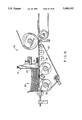
- FIG. 18 shows a stack of foldable blanks entering the feed gate of a finishing machine used for processing foldable blanks.
- FIGS. 19-25 depict various embodiments having a feed gate notch on the respective right or left, bottom, front, rear and top end flaps.
- a carton blank generally designated A comprises cover panel 4, top panel 5, rear panel 6, bottom panel 7 and front panel 8 hingedly connected in the order named. More specifically, cover panel 4 and top panel 5 are hingedly connected by score line 9; top panel 5 and rear panel 6 are hingedly connected by score line 10; rear panel 6 and bottom panel 7 are hingedly connected by line 11 and bottom panel 7 and front panel 8 are hingedly connected by score line 12.
- score line 9 is formed in the downward direction with reference to the upper surface of blank A.
- score lines 9-12 permit simple manipulation of blank A to form an assembled carton for universal packaging of pre-selected products.
- cover panel 4 includes first and second end flaps 4A and 4B, intermediate tear-away strip 4C and front panel portion 4D.
- Strip 4C is defined by upper and lower die-cuts or perforations 13 and 14. Like score lines 9-12, die-cuts 13 and 14 are formed in a downward direction with reference to the upper surface of blank A. Tear-away strip 4C is releasably secured to front panel 4 by perforation 13 and releasably secured to front panel portion 4D by perforation 14.
- Main panels 4-8 have first and second end flaps hingedly connected by adjacent fold lines. Specifically, first and second bottom panel end flaps 7A and 7B are hingedly connected to bottom panel 7 by intermediate fold lines 15A and 15B, respectively.
- first and second front panel end flaps 8A and 8B are hingedly connected to front panel 8 by intermediate fold lines 16A and 16B; first and second top panel end flaps 5A and 5B are hingedly connected to top panel 5 by intermediate fold lines 17A and 17B; first and second rear panel end flaps 6A and 6B are hingedly connected to rear panel 6 by intermediate fold lines 18A and 18B; and first and second cover panel end flaps 4A and 4B are hingedly connected to cover panel 4 by intermediate fold lines 19A and 19B.
- FIG. 18 illustrates a portion of an adhesive applicator, generally designated 50, having an adjustable feed gate 51 which has opening 54 defined between feed contact 52 and belt 53. Opening 54 is used as a controlled entry point for transporting cut, printed blanks, one at a time, into applicator 50.
- Feed gate 51 may be a rectangular piece of metal adapted with an angular, metal feed contact 52 at the lower end.
- the tolerance between feed contact 52 and the upper surface of belt 53 (defining opening 54) is selected to approximate a single thickness of paperboard (approximately 1/24,000 of an inch).
- Cut, printed blanks 55 are stacked and placed on motor-driven conveyor belt 53 which delivers the blanks one at a time into finishing machine 50, starting with the lowest blank in the stack, designated 56.
- a motorized feed chain (not shown) inside feed gate 51 displaces protrusion 57 and applies downward pressure on remaining stack 55.
- blank 56 accelerates from zero lateral velocity to the speed of driving belt 53.
- Stack 55 provides a downward load which creates a drag on blank 56 as it passes under feed contact 52. Without feed gate engaging notch 71, this drag would smear the bleed line ink on blank 56. Engaging notch 71 allows blank 56 to interface with feed gate 51 without contacting the bleed line.
- feed gate engaging notch 71 is centered along the edge of bottom panel end flap 7B. But, this is not a requirement or limitation for the present invention. Engaging notch 71 can be formed anywhere on the edge of bottom panel end flap 7B to adjust for different gate configurations and/or dimensions. Regardless of position, seal engaging edges 72 must extend for an appropriate length on either side of engaging notch 71.
- engaging notch 71 and seal engaging edges 72 can be placed on any main panel end flap to provide seven (7) additional embodiments depending on finishing equipment or process requirements.
- rear panel end flap 6B is defined by front edge 40A, top edge 40B, bottom edge 40C and score line 18B.
- Offset portion 41 is formed within a lower area of rear panel end flap 6B adjacent to front edge 40A, bottom edge 40C and score line 18B.
- Portion 41 is offset or projected from the plane of carton blank A in the same direction as score lines 912 and perforations 13 and 14. The projected dimension is approximately equal to a single thickness of paperboard stock.
- Breakaway portion 36 is formed in an upper portion of rear panel end flaps 6A and 6B by breakaway perforations or lines of weakness 37 die-cut in the paperboard stock. Like score lines 9-12, die-cuts 13-14 and offset portion 41, breakaway perforation 37 is die-cut in the same downward direction with reference to the upper surface of blank A.
- breakaway portion 36 of blank A is adapted for adhesive attachment to an underlying portion of top panel end flaps 5A and 5B in an assembled carton.
- Adhesive attachment is preferably achieved by extending single lines of adhesive which are typically used to secure the end wall-forming flaps at both ends of an erected carton.
- FIG. 2A is a plan view of rear panel end flap 6B showing the placement of breakaway portion 36 and offset portion 41.
- FIG. 2B illustrates an end view of rear panel end flap 6B with offset portion 41 and score lines 10 and 11.
- all die-cuttings and die-stampings are projected in the same downward direction from the upper surface of carton blank A.
- This unitary configuration differs from the prior art technique illustrated by FIG. 2C.
- carton blank A is partially assembled by arranging bottom panel end flap 7A, front panel end flap 8A, top panel end flap 5A (not shown) and rear panel end flap 6A according to the art-recognized flap folding sequence.
- Bottom panel end flap 7A is first folded along score line 15A; front panel end flap 8A is next folded along score line 16A and rear panel end flap 6A is last folded along score line 18A to contact bottom panel end flap 7A and front panel end flap 8A.
- offset portion 41 is projected inwardly toward bottom panel end flap 7A for a distance approximately equal to a single thickness of paperboard stock.
- Front edge 40A of rear panel end flap 6A cooperates with front panel end flap 8A and offset portion 41 cooperates with bottom panel end flap 7A.
- rear panel end flap 6A simultaneously contacts front panel end flap 8A and bottom panel end flap 7A to provide improved adhesive attachment for the end wall forming flaps.
- a carton is assembled by first forming an intermediate carton sleeve.
- Front panel 8 of blank A is folded along score line 12 to overlie a portion of bottom panel 7.
- Glue is then applied to the interior side of cover panel 4 or the exterior side of front panel 8.
- Top panel 5 is folded about score line 10 over rear panel 6 and bottom panel 7.
- cover portion 4D is adhesively secured to the exterior surface of front panel 8 to form a carton sleeve.
- a carton is next formed from this partially assembled sleeve.
- a carton sleeve is squared-up to form open-ended carton 32 having bottom end 34 and top end 33, as shown in FIG. 4A.
- First and second top panel end flaps 5A and 5B are substantially co-planar with top panel 5; rear panel end flaps 6A and 6B are substantially co-planar with rear panel 6; bottom panel end flaps 7A and 7B are substantially co-planar with bottom panel 7; and front panel end flaps 8A and 8B are substantially co-planar with front panel 8.
- cover panel end flaps 4A and 4B are substantially co-planar with cover panel 4 (not shown).
- bottom end 34 is closed first according to the description provided in connection with FIG. 4A.
- bottom end 34 of partially assembled carton 32 is closed by folding bottom panel end flap 7A first; front panel end flap 8A second; cover panel end flap 5A third; and rear panel end flap 6A fourth.
- An identical flap-folding sequence is subsequently performed to close top end 33 of carton 32.
- Bottom panel end flap 7A is first folded substantially perpendicular to bottom panel 7. In this position, bottom panel end flap 7A essentially closes bottom end 34 of partially assembled carton 32. Front panel end flap 8A is next folded inwardly and substantially perpendicular to front panel 8 to overlap a portion of bottom panel end flap 7A. Top panel end flap 5A is then folded down to overlie a portion of front panel end flap 8A and a coincident portion of bottom panel end flap 7A.
- a single line of adhesive 38 is deposited on the lower and rearward portion of bottom panel end flap 7A using a conventional applicator nozzle.
- offset portion 41 positioned on rear panel end flap 6A, single glue line 38 is deposited on the flat surface of bottom panel end flap 7A. This flat surface provides for regular operating conditions and uniform glue deposits which improve adhesion between the end wall-forming flaps.
- single glue line 38 is extended onto the exterior surface of top panel end flap 5A so that breakaway feature 36 will be secured to underlying portion of top panel end flap 5A in a fully assembled carton.
- rear panel end flap A with offset portion 41 is folded fourth and last to adhesively secure the end wall-forming flaps of blank A.
- Rear panel end flap 6A directly contacts bottom panel end flap 7A about a major area of offset portion 41. This co-planar arrangement improves adhesion between the end flaps and provides increased stability for a subsequently assembled carton.
- preselected solid or semi-solid products such as candy, ice cream, snack chips, novelty items and the like are delivered to the receptacle formed by main panels 4-8 and the end wall-forming flaps which close bottom end 34 of partially assembled carton 32.
- An identical flap-folding sequence is subsequently performed on top end 33 of partially assembled carton 32.
- bottom panel end flap 7B is folded first
- front panel end flap 8B is folded second
- top panel end flap 5B is folded third
- rear panel end flap 6B is folded fourth and last.
- front panel 8 and front panel end flaps 8A and 8B of blank A are designed to minimize paperboard consumption without compromising the structural integrity of a corresponding carton.
- Blanks of the type described in this specification are typically manufactured from large paperboard sheets in a ten-up (two rows of five) configuration. Individual blanks are "nested" on plural sides to provide an efficient layout for the blanking operation.
- blank 1 and adjacent blank 2 are nested along interface 3 in a manner previously unknown to the art.
- outer edge 43 of front panel 8 (blank 1) and outer edge 44 of cover panel 4 (blank 2) are formed with a single knifing operation.
- blank A provides a "tighter" nesting configuration, significantly reduces raw material costs and contributes to manufacturing efficiency.
- Blank B illustrated in FIG. 8 is substantially identical to blank A of FIG. 1. The principal difference is provided by membrane 22A which is hingedly connected to front panel end flap 8A along a minor or major length of fold line 20A at bottom end 34.
- bottom panel end flap 7A has recess 24A formed in outer marginal edge 45A. Recess 24A is adapted to cooperate with membrane 22A in the folded condition.
- the nesting configuration for blank B is similar to the nesting configuration for blank A as shown in FIG. 7. Additional paperboard is required for the blank B configuration depending on the width dimension of membrane 22A. It will be appreciated that blank B is useful for those applications which require some degree of structural integrity and leakproof performance for cartons used to package semi-solid goods. A corresponding carton in the open condition is shown in FIG. 10.
- Blank C illustrated in FIG. 11 is substantially identical to blank B of FIG. 9. The principal difference is provided by second membrane 22B which is hingedly connected to front panel end flap 8B along a minor or major length of fold line 20B at top end 33.
- bottom panel end flap 7B has second recess 24B formed in outer marginal edge 45B. Recess 24B is adapted to cooperate with membrane 22B in the folded condition.
- blank C is similar to that of blank A of FIG. 7 and blank B of FIG. 9. Additional paperboard is necessarily required for the placement of membrane 22B on front panel end flap 8B. Blank C is useful for those applications which require an extra degree of structural integrity and leakproof performance for an assembled carton as shown in FIG. 13.
- Blank D illustrated in FIG. 13 is substantially identical to blank C of FIG. 11. The only difference is provided by membrane 22C which is hingedly connected to front panel 8 along a minor or major length of fold line 20C. As illustrated by FIG. 15, the nesting configuration for blank D is similar to that of blanks A, B and C as illustrated by FIGS. 7, 9 and 12. It will be appreciated that blank D maximizes the use of paperboard stock but optimizes structural integrity and leakproof characteristics. A corresponding carton in the open condition is shown in FIG. 16.
- carton blank E is similar to carton blank D as shown in FIG. 14. Corresponding reference numerals identify similar features of these two embodiments.
- blank E of FIG. 17 includes only two lip membranes 22A and 22B extending from the upper edges of front panel end flaps 8A and 8B. But, as previously disclosed, the carton blank can be constructed with no lip membranes as shown in FIG. 1; one lip membrane as shown in FIG. 8 or three lip membranes in the embodiment of FIG. 14.
- FIG. 17 illustrates that rear panel end flaps 6A and 6B do not include offset portion 41. Instead, end flaps 6A and 6B include tabs 50A and 50B defined by score lines or flex joints 52A and 52B, respectively. Like other die stampings in carton blank E, score lines 52A and 52B are formed in a single, downward direction with reference to the plane of the blank.
- tabs 50A and 50B allows for flexing of the paperboard and permits intimate contact between the remaining portions of end flaps 6A and 6B and the glue line deposited during carton assembly. A secure bond is achieved, thereby avoiding gaps in the end walls and reducing the possibility of semi-solid leakage. This embodiment contributes to a smoother, more attractive appearance for the carton.
Landscapes
- Engineering & Computer Science (AREA)
- Mechanical Engineering (AREA)
- Cartons (AREA)
Abstract
Description
Claims (32)
Priority Applications (2)
| Application Number | Priority Date | Filing Date | Title |
|---|---|---|---|
| US08/198,993 US5484102A (en) | 1991-11-25 | 1994-02-18 | Folding carton blank with feed gate engaging notch |
| US08/458,896 US5588584A (en) | 1991-11-25 | 1995-06-02 | Lipless folding cartons and blanks |
Applications Claiming Priority (3)
| Application Number | Priority Date | Filing Date | Title |
|---|---|---|---|
| US79675891A | 1991-11-25 | 1991-11-25 | |
| US07/974,975 US5288012A (en) | 1991-11-25 | 1992-11-12 | Folding carton for containing a semi-solid product and blank for constructing same |
| US08/198,993 US5484102A (en) | 1991-11-25 | 1994-02-18 | Folding carton blank with feed gate engaging notch |
Related Parent Applications (1)
| Application Number | Title | Priority Date | Filing Date |
|---|---|---|---|
| US07/974,975 Continuation-In-Part US5288012A (en) | 1991-11-25 | 1992-11-12 | Folding carton for containing a semi-solid product and blank for constructing same |
Related Child Applications (1)
| Application Number | Title | Priority Date | Filing Date |
|---|---|---|---|
| US08/458,896 Continuation US5588584A (en) | 1991-11-25 | 1995-06-02 | Lipless folding cartons and blanks |
Publications (1)
| Publication Number | Publication Date |
|---|---|
| US5484102A true US5484102A (en) | 1996-01-16 |
Family
ID=27121777
Family Applications (2)
| Application Number | Title | Priority Date | Filing Date |
|---|---|---|---|
| US08/198,993 Expired - Lifetime US5484102A (en) | 1991-11-25 | 1994-02-18 | Folding carton blank with feed gate engaging notch |
| US08/458,896 Expired - Lifetime US5588584A (en) | 1991-11-25 | 1995-06-02 | Lipless folding cartons and blanks |
Family Applications After (1)
| Application Number | Title | Priority Date | Filing Date |
|---|---|---|---|
| US08/458,896 Expired - Lifetime US5588584A (en) | 1991-11-25 | 1995-06-02 | Lipless folding cartons and blanks |
Country Status (1)
| Country | Link |
|---|---|
| US (2) | US5484102A (en) |
Cited By (13)
| Publication number | Priority date | Publication date | Assignee | Title |
|---|---|---|---|---|
| US5588584A (en) * | 1991-11-25 | 1996-12-31 | Fold-Pak Corporation | Lipless folding cartons and blanks |
| US5746371A (en) * | 1995-12-29 | 1998-05-05 | Ben-Haim; Amit | Cutting brick folding carton and blank |
| US5947368A (en) * | 1997-05-02 | 1999-09-07 | Fold-Pak Corporation | Folding carton and blank with reclosure means |
| US6206280B1 (en) | 1997-05-02 | 2001-03-27 | Fold-Pak Corporation | Folding carton and blank with reclosure means |
| US20040007613A1 (en) * | 2002-07-10 | 2004-01-15 | Quaintance Benjamin W. | Offset dove tail locks |
| US20070290026A1 (en) * | 2006-06-16 | 2007-12-20 | Kastanek Raymond S | Gusseted Carton Having Upper and Lower Storage Compartments |
| US7669755B2 (en) | 2004-08-10 | 2010-03-02 | Graphic Packaging International, Inc. | Carton with hinged lid |
| US20110028292A1 (en) * | 2008-04-11 | 2011-02-03 | Qin Zhang | Method And System For Bleed Control On Packaging Layout |
| US8740050B2 (en) | 2010-12-06 | 2014-06-03 | Graphic Packaging International, Inc. | Carton with lid |
| US10053259B2 (en) | 2015-02-27 | 2018-08-21 | Graphic Packaging International, Llc | Construct with locking features |
| US10086972B2 (en) | 2015-06-09 | 2018-10-02 | Graphic Packaging International, Llc | Carton with locking feature |
| US10106363B1 (en) * | 2017-08-04 | 2018-10-23 | Packaging Progressions, Inc. | Flap folder |
| US11312531B1 (en) * | 2021-10-14 | 2022-04-26 | Rachman Ezell | Dual-action carton separation system and method of use |
Families Citing this family (4)
| Publication number | Priority date | Publication date | Assignee | Title |
|---|---|---|---|---|
| US20100136164A1 (en) * | 2004-08-25 | 2010-06-03 | Cadbury Adams Usa Llc | Package assembly for multi-modality taste chewing gum compositions |
| US20090150231A1 (en) * | 2005-05-23 | 2009-06-11 | Cadbury Adams Usa Llc | Package assembly for multi-modality functional ingredients in chewing gum compositions |
| CA2851887A1 (en) | 2013-05-15 | 2014-11-15 | Rock-Tenn Shared Services, Llc | Ice cream container and method of manufacturing same |
| USD726533S1 (en) | 2013-05-15 | 2015-04-14 | Rock-Tenn Shared Services, Llc | Ice cream container |
Family Cites Families (23)
| Publication number | Priority date | Publication date | Assignee | Title |
|---|---|---|---|---|
| US2342198A (en) * | 1940-04-04 | 1944-02-22 | Pneumatic Scale Corp | Method of making cartons |
| US3168974A (en) * | 1960-11-14 | 1965-02-09 | Kvp Sutherland Paper Co | Covered carton |
| US3219257A (en) * | 1963-08-16 | 1965-11-23 | Ralph F Anderson | Carton construction |
| US3295743A (en) * | 1965-03-11 | 1967-01-03 | Waldorf Paper Prod Co | Ice cream carton |
| US3315870A (en) * | 1965-04-22 | 1967-04-25 | Mead Corp | Top opening carton |
| US3281059A (en) * | 1965-10-23 | 1966-10-25 | Brown Co | Tear strip structure |
| US3361328A (en) * | 1967-07-13 | 1968-01-02 | Brown Co | Square end carton structure |
| US3524581A (en) * | 1968-08-06 | 1970-08-18 | Brown Co | Carton structure |
| US3735916A (en) * | 1971-05-03 | 1973-05-29 | Brown Company Kalamazoo | Ice cream carton having readily removable divider and support means |
| US3750931A (en) * | 1972-06-19 | 1973-08-07 | Hoerner Waldorf Corp | Carton opening means |
| CA994306A (en) * | 1973-01-22 | 1976-08-03 | American Can Company | End wall construction for a carton |
| US3959950A (en) * | 1975-03-17 | 1976-06-01 | Nobuyoshi Fukuda | Packaging system |
| US3981434A (en) * | 1975-04-10 | 1976-09-21 | American Can Company | Easy opening carton for frozen comestible |
| US4508258A (en) * | 1982-05-10 | 1985-04-02 | Manville Service Corporation | Sleeve-style beverage carton |
| US4712689A (en) * | 1986-05-23 | 1987-12-15 | Froom Thomas W | Ice-cream carton, carton blank, and method of erecting same |
| US4712730A (en) * | 1986-05-23 | 1987-12-15 | Froom Thomas W | Ice-cream carton, carton blank, and method of erecting same |
| US4756470A (en) * | 1987-03-04 | 1988-07-12 | Rolph-Clark-Stone Packaging Corporation | Carton and blank for packaging ice cream or the like |
| US4771939A (en) * | 1987-08-28 | 1988-09-20 | Nekoosa Packaging Corporation | Center special slotted container |
| US4838432A (en) * | 1987-10-13 | 1989-06-13 | Somerville Packaging Corporation | Carton and blank for packaging ice cream and the like |
| US4907698A (en) * | 1989-03-17 | 1990-03-13 | James River Corporation | Ice cream carton, carton blank, and method of assembly |
| US5033622A (en) * | 1990-09-10 | 1991-07-23 | Paperboard Industries, Inc. | Carton and blank for packaging ice cream and the like |
| US5484102A (en) * | 1991-11-25 | 1996-01-16 | Fold-Pak Corporation | Folding carton blank with feed gate engaging notch |
| US5288012A (en) * | 1991-11-25 | 1994-02-22 | Fold-Pak Corporation | Folding carton for containing a semi-solid product and blank for constructing same |
-
1994
- 1994-02-18 US US08/198,993 patent/US5484102A/en not_active Expired - Lifetime
-
1995
- 1995-06-02 US US08/458,896 patent/US5588584A/en not_active Expired - Lifetime
Cited By (16)
| Publication number | Priority date | Publication date | Assignee | Title |
|---|---|---|---|---|
| US5588584A (en) * | 1991-11-25 | 1996-12-31 | Fold-Pak Corporation | Lipless folding cartons and blanks |
| US5746371A (en) * | 1995-12-29 | 1998-05-05 | Ben-Haim; Amit | Cutting brick folding carton and blank |
| US5947368A (en) * | 1997-05-02 | 1999-09-07 | Fold-Pak Corporation | Folding carton and blank with reclosure means |
| US6206280B1 (en) | 1997-05-02 | 2001-03-27 | Fold-Pak Corporation | Folding carton and blank with reclosure means |
| US20040007613A1 (en) * | 2002-07-10 | 2004-01-15 | Quaintance Benjamin W. | Offset dove tail locks |
| US7036718B2 (en) * | 2002-07-10 | 2006-05-02 | International Paper Company | Offset dove tail locks |
| US7669755B2 (en) | 2004-08-10 | 2010-03-02 | Graphic Packaging International, Inc. | Carton with hinged lid |
| US20070290026A1 (en) * | 2006-06-16 | 2007-12-20 | Kastanek Raymond S | Gusseted Carton Having Upper and Lower Storage Compartments |
| US20110028292A1 (en) * | 2008-04-11 | 2011-02-03 | Qin Zhang | Method And System For Bleed Control On Packaging Layout |
| US8469868B2 (en) * | 2008-04-11 | 2013-06-25 | Founder International Co., Ltd. (Beijing) | Method and system for bleed control on packaging layout |
| US8740050B2 (en) | 2010-12-06 | 2014-06-03 | Graphic Packaging International, Inc. | Carton with lid |
| US10053259B2 (en) | 2015-02-27 | 2018-08-21 | Graphic Packaging International, Llc | Construct with locking features |
| US10086972B2 (en) | 2015-06-09 | 2018-10-02 | Graphic Packaging International, Llc | Carton with locking feature |
| US10106363B1 (en) * | 2017-08-04 | 2018-10-23 | Packaging Progressions, Inc. | Flap folder |
| WO2019027499A1 (en) * | 2017-08-04 | 2019-02-07 | Packaging Progressions, Inc. | Flap folder |
| US11312531B1 (en) * | 2021-10-14 | 2022-04-26 | Rachman Ezell | Dual-action carton separation system and method of use |
Also Published As
| Publication number | Publication date |
|---|---|
| US5588584A (en) | 1996-12-31 |
Similar Documents
| Publication | Publication Date | Title |
|---|---|---|
| US5351881A (en) | Folding carton blank | |
| US5484102A (en) | Folding carton blank with feed gate engaging notch | |
| EP0763473B1 (en) | Carton, blank for erecting the said carton and process for the assembly of said blank into a state from which it can be erected into said carton | |
| US5505372A (en) | Carton blank and carton | |
| US4008849A (en) | Bidirectional tear strip means for cartons and the like | |
| EP1034112B1 (en) | Paperboard carton with end wall handles | |
| US4792038A (en) | Basket-type carrier for articles of various sizes | |
| US4548352A (en) | Pop-out carton | |
| US3861583A (en) | Reclosable carton | |
| US4558815A (en) | Nesting open-top containers for popcorn and the like | |
| US4838479A (en) | Heavy duty carrying handle for a can carton | |
| US4121757A (en) | Flap arrangement for a carrier carton | |
| CA1295974C (en) | Basket-type carrier for elongated articles | |
| CA2088310A1 (en) | Gable-top type carton and blank for forming the same | |
| AU8207182A (en) | Easy open carton | |
| CA1223236A (en) | Hinged lid container having finished edges | |
| US4828164A (en) | Folded carton having integral header | |
| US4228946A (en) | Carton | |
| US5474231A (en) | Adhesive ports for folding cartons | |
| US4144996A (en) | Hinged carton | |
| US20240359858A1 (en) | Carton For Articles | |
| US5746371A (en) | Cutting brick folding carton and blank | |
| US5573177A (en) | Reclosable hinged flap | |
| AU2024211874A1 (en) | Container with barrier member | |
| US5667467A (en) | Method for forming an effective seal for a carton |
Legal Events
| Date | Code | Title | Description |
|---|---|---|---|
| AS | Assignment |
Owner name: FOLD-PAK CORPORATION, NEW YORK Free format text: ASSIGNMENT OF ASSIGNORS INTEREST;ASSIGNOR:DEMAY, KARL F.;REEL/FRAME:006947/0236 Effective date: 19940228 |
|
| STCF | Information on status: patent grant |
Free format text: PATENTED CASE |
|
| FEPP | Fee payment procedure |
Free format text: PAYOR NUMBER ASSIGNED (ORIGINAL EVENT CODE: ASPN); ENTITY STATUS OF PATENT OWNER: LARGE ENTITY Free format text: PAT HLDR NO LONGER CLAIMS SMALL ENT STAT AS SMALL BUSINESS (ORIGINAL EVENT CODE: LSM2); ENTITY STATUS OF PATENT OWNER: LARGE ENTITY |
|
| FPAY | Fee payment |
Year of fee payment: 4 |
|
| AS | Assignment |
Owner name: GULF STATES PAPER CORPORATION, ALABAMA Free format text: ASSIGNMENT OF ASSIGNORS INTEREST;ASSIGNOR:FOLD-PAK CORPORATION, A NEW YORK CORPORATION;REEL/FRAME:012745/0282 Effective date: 20020303 |
|
| AS | Assignment |
Owner name: GSPC ENTERPRISE INC., ALABAMA Free format text: ASSIGNMENT OF ASSIGNORS INTEREST;ASSIGNOR:GULF STATES PAPER CORPORATION;REEL/FRAME:013669/0278 Effective date: 20021223 |
|
| FPAY | Fee payment |
Year of fee payment: 8 |
|
| AS | Assignment |
Owner name: ROCK-TENN PACKAGING AND PAPERBOARD, LLC, GEORGIA Free format text: ASSIGNMENT OF ASSIGNORS INTEREST;ASSIGNOR:GSPC ENTERPRISES, INC.;REEL/FRAME:016360/0093 Effective date: 20050606 |
|
| AS | Assignment |
Owner name: ROCK-TENN SHARED SERVICES, LLC, GEORGIA Free format text: ASSIGNMENT OF ASSIGNORS INTEREST;ASSIGNOR:ROCK-TENN PACKAGING AND PAPERBOARD, LLC;REEL/FRAME:016263/0525 Effective date: 20050715 |
|
| AS | Assignment |
Owner name: WACHOVIA BANK, NATIONAL ASSOCIATION, AS ADMINISTRA Free format text: NOTICE OF GRANT OF SECURITY INTEREST;ASSIGNOR:ROCK-TENN SHARED SERVICES, LLC;REEL/FRAME:016580/0708 Effective date: 20050606 |
|
| FPAY | Fee payment |
Year of fee payment: 12 |
|
| AS | Assignment |
Owner name: WACHOVIA BANK, NATIONAL ASSOCIATION, AS COLLATERAL Free format text: NOTICE OF GRANT OF SECURITY INTEREST;ASSIGNOR:ROCK-TENN SHARED SERVICES, LLC;REEL/FRAME:020627/0901 Effective date: 20080305 |
|
| AS | Assignment |
Owner name: ROCK-TENN SHARED SERVICES, LLC, GEORGIA Free format text: RELEASE BY SECURED PARTY;ASSIGNOR:WELLS FARGO BANK, NATIONAL ASSOCIATION;REEL/FRAME:026413/0958 Effective date: 20110527 |