US5474425A - Wind turbine rotor blade - Google Patents
Wind turbine rotor blade Download PDFInfo
- Publication number
- US5474425A US5474425A US08/120,658 US12065893A US5474425A US 5474425 A US5474425 A US 5474425A US 12065893 A US12065893 A US 12065893A US 5474425 A US5474425 A US 5474425A
- Authority
- US
- United States
- Prior art keywords
- blade
- wind turbine
- degrees
- rotor
- airfoil
- Prior art date
- Legal status (The legal status is an assumption and is not a legal conclusion. Google has not performed a legal analysis and makes no representation as to the accuracy of the status listed.)
- Expired - Fee Related
Links
- 230000001105 regulatory effect Effects 0.000 claims abstract description 13
- 239000002023 wood Substances 0.000 claims abstract description 5
- 230000003247 decreasing effect Effects 0.000 claims description 3
- 239000011521 glass Substances 0.000 claims description 3
- 229920002430 Fibre-reinforced plastic Polymers 0.000 claims 1
- 239000011151 fibre-reinforced plastic Substances 0.000 claims 1
- 229920000642 polymer Polymers 0.000 claims 1
- 238000004519 manufacturing process Methods 0.000 description 10
- 238000013461 design Methods 0.000 description 8
- 230000008901 benefit Effects 0.000 description 5
- 230000008859 change Effects 0.000 description 4
- 230000007423 decrease Effects 0.000 description 4
- 230000000694 effects Effects 0.000 description 4
- 230000005611 electricity Effects 0.000 description 4
- 238000012423 maintenance Methods 0.000 description 4
- 230000007246 mechanism Effects 0.000 description 4
- 238000000034 method Methods 0.000 description 4
- 241000341910 Vesta Species 0.000 description 3
- 238000013459 approach Methods 0.000 description 3
- 238000010276 construction Methods 0.000 description 3
- 230000008569 process Effects 0.000 description 3
- 238000009825 accumulation Methods 0.000 description 2
- 230000008030 elimination Effects 0.000 description 2
- 238000003379 elimination reaction Methods 0.000 description 2
- 239000003822 epoxy resin Substances 0.000 description 2
- 229920000647 polyepoxide Polymers 0.000 description 2
- 230000009467 reduction Effects 0.000 description 2
- 230000003746 surface roughness Effects 0.000 description 2
- OKTJSMMVPCPJKN-UHFFFAOYSA-N Carbon Chemical compound [C] OKTJSMMVPCPJKN-UHFFFAOYSA-N 0.000 description 1
- 239000004593 Epoxy Substances 0.000 description 1
- 238000005299 abrasion Methods 0.000 description 1
- 238000003491 array Methods 0.000 description 1
- 238000005452 bending Methods 0.000 description 1
- XIWFQDBQMCDYJT-UHFFFAOYSA-M benzyl-dimethyl-tridecylazanium;chloride Chemical compound [Cl-].CCCCCCCCCCCCC[N+](C)(C)CC1=CC=CC=C1 XIWFQDBQMCDYJT-UHFFFAOYSA-M 0.000 description 1
- 230000033228 biological regulation Effects 0.000 description 1
- 229910052799 carbon Inorganic materials 0.000 description 1
- 238000006243 chemical reaction Methods 0.000 description 1
- 238000002485 combustion reaction Methods 0.000 description 1
- 230000001276 controlling effect Effects 0.000 description 1
- 238000007796 conventional method Methods 0.000 description 1
- 230000008878 coupling Effects 0.000 description 1
- 238000010168 coupling process Methods 0.000 description 1
- 238000005859 coupling reaction Methods 0.000 description 1
- 230000007812 deficiency Effects 0.000 description 1
- 238000011161 development Methods 0.000 description 1
- 230000002349 favourable effect Effects 0.000 description 1
- 239000012530 fluid Substances 0.000 description 1
- 239000002803 fossil fuel Substances 0.000 description 1
- 239000012634 fragment Substances 0.000 description 1
- 239000000446 fuel Substances 0.000 description 1
- 238000009434 installation Methods 0.000 description 1
- 239000011120 plywood Substances 0.000 description 1
- 239000012783 reinforcing fiber Substances 0.000 description 1
- 239000011435 rock Substances 0.000 description 1
- 239000007787 solid Substances 0.000 description 1
Images


Classifications
-
- F—MECHANICAL ENGINEERING; LIGHTING; HEATING; WEAPONS; BLASTING
- F03—MACHINES OR ENGINES FOR LIQUIDS; WIND, SPRING, OR WEIGHT MOTORS; PRODUCING MECHANICAL POWER OR A REACTIVE PROPULSIVE THRUST, NOT OTHERWISE PROVIDED FOR
- F03D—WIND MOTORS
- F03D1/00—Wind motors with rotation axis substantially parallel to the air flow entering the rotor
- F03D1/06—Rotors
- F03D1/065—Rotors characterised by their construction elements
-
- F—MECHANICAL ENGINEERING; LIGHTING; HEATING; WEAPONS; BLASTING
- F05—INDEXING SCHEMES RELATING TO ENGINES OR PUMPS IN VARIOUS SUBCLASSES OF CLASSES F01-F04
- F05B—INDEXING SCHEME RELATING TO WIND, SPRING, WEIGHT, INERTIA OR LIKE MOTORS, TO MACHINES OR ENGINES FOR LIQUIDS COVERED BY SUBCLASSES F03B, F03D AND F03G
- F05B2240/00—Components
- F05B2240/20—Rotors
- F05B2240/30—Characteristics of rotor blades, i.e. of any element transforming dynamic fluid energy to or from rotational energy and being attached to a rotor
-
- Y—GENERAL TAGGING OF NEW TECHNOLOGICAL DEVELOPMENTS; GENERAL TAGGING OF CROSS-SECTIONAL TECHNOLOGIES SPANNING OVER SEVERAL SECTIONS OF THE IPC; TECHNICAL SUBJECTS COVERED BY FORMER USPC CROSS-REFERENCE ART COLLECTIONS [XRACs] AND DIGESTS
- Y02—TECHNOLOGIES OR APPLICATIONS FOR MITIGATION OR ADAPTATION AGAINST CLIMATE CHANGE
- Y02E—REDUCTION OF GREENHOUSE GAS [GHG] EMISSIONS, RELATED TO ENERGY GENERATION, TRANSMISSION OR DISTRIBUTION
- Y02E10/00—Energy generation through renewable energy sources
- Y02E10/70—Wind energy
- Y02E10/72—Wind turbines with rotation axis in wind direction
Definitions
- the present invention relates to wind turbines and to novel, improved wind turbine rotors and rotor blades.
- c is the local chord of a blade; i.e. the chord at a particular spanwise station
- Chordwise Station is a location at a designated distance from the leading edge of a blade
- h is the height of the mean chord line of a blade at a given chordwise station relative to a zero level
- R is the distance from the axis of rotation of a rotor to the tip of the rotor blades
- r is the distance from the axis of rotation of a rotor to a particular spanwise station
- Spanwise station is a location along the span of a blade
- t is the thickness of the blade at a particular chordwise station
- Tip Speed Ratio is tip speed divided by wind speed
- HAWT's horizontal axis wind turbines
- the rotor is designed to rotate under the influence of the wind. This rotation is subsequently used to generate electric power by means of a drive train, gearbox, and generator.
- the resulting power is supplied to the local utility by means of transformers and substation-controlled connections.
- transformers and substation-controlled connections generally, wind energy projects have large numbers of wind turbine generating systems at locations with favorable wind conditions.
- wind farms are located in the state of California.
- HAWT wind turbines are two notable sub-classes--stall-regulated rotors and those with active or partially active adjustable pitch rotors.
- Stall-regulated rotors have blades which do not change pitch and depend on careful aerodynamic blade design for peak power control.
- Wind turbines with active and partially active pitch systems include a mechanism, usually hydraulic, to physically change the orientation or "pitch" of the blade, either at its root or an outboard station, in such a way so as to limit the power generated by the rotor to a selected maximum value. This limitation is generally dictated by maximum power or load capabilities of other system components.
- Wind turbine rotors with adjustable pitch blades are complicated and expensive because of the mechanism required to adjust the blade pitch and to control this adjustment as wind conditions change. Furthermore, maintenance of these rotors is a burden, especially in those not uncommon applications in which wind turbines are employed in considerable numbers at remote locations and in third world countries and other locales where skilled mechanics are more than likely not available.
- the rotor blades employ National Renewable Energy Laboratory (NREL) airfoil profiles or relatives of those profiles toward the root and tip and near the midspan of the blade. Intermediate profiles are developed by lofting.
- NREL National Renewable Energy Laboratory
- NREL airfoil profiles employed in the present invention are selected from a family of profiles with thick sections. These profiles have characteristics which make them usable in rotors with radii in the 25-50 foot range, and they have the advantage of being relatively insensitive to blade surface roughness. Profiles with low, medium, and high coefficients of lift are employed at the defined blade tip, midspan, and root stations.
- the root, midspan, and tip segments of the blade have significantly different aerodynamic characteristics, all obtained without any significant reduction in lift-to-drag ratio (L/D).
- the result is a wind turbine which generates power more efficiently, which has improved soiled blade performance characteristics, and which is less highly loaded. This reduces stresses on the wind turbine components, reducing maintenance requirements and increasing service life.
- the power coefficient of a blade employing the principles of the present invention is a maximum at relatively low wind speeds (ca. 15-30 mph). Therefore, wind turbines employing the principles of the present invention exhibit superior performance in locales in which the prevailing winds blow at these lower speeds.
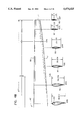
- FIG. 1 is a front view of a wind turbine embodying the principles of the present invention and of the tower on which the wind turbine is mounted;
- FIG. 2 is a side view of the wind turbine and its supporting tower
- FIG. 3 is a somewhat simplified side view of the wind turbine, drawn to an enlarged scale to more clearly show its components;
- FIG. 4 shows the relationship between FIGS. 4A and 4B which, taken together, show the plan of one of the wind turbine's two essentially identical blades and the profile of the blade at representative stations along its span;
- FIG. 4C shows, pictorially, the lofting process employed in designing a wind turbine blade in accord with the principles of the present invention
- FIG. 5 shows, in more detail, the configuration of an NREL airfoil employed near the root of the wind turbine blade
- FIG. 6 is a plot of mean chord line versus chordwise station for the airfoil shown in FIG. 5;
- FIG. 7 is a plot of thickness ratio versus chordwise station for the blade of FIG. 5;
- FIGS. 5, 6 and 7 positively define the airfoil shown in FIG. 5;
- FIGS. 8, 9, and 10 are figures corresponding to FIGS. 5-7; they absolutely define the second NREL airfoil profile which appears in FIG. 8; that airfoil is employed near the midspan of the blade;
- FIGS. 11-13 correspond to FIGS. 5-7 and absolutely define a third NREL airfoil which appears in FIG. 11 and is employed near the tip of the blade;
- FIGS. 14 and 15 are plots of local chord/rotor radius (c/R) and local twist versus spanwise station for the blade shown in FIG. 4; these figures accordingly further define the configuration of the blade;
- FIG. 16 is a plot of rotor power coefficient versus wind speed for the blade shown in FIG. 4 and for blades which differ from the latter only in the blade pitch; this figure accordingly reflects the efficiency of the FIG. 1 turbine rotor over the range of wind speeds encompassed by the figure;
- FIG. 17 is a similar figure showing the rotor power coefficient of the FIG. 1 turbine with the blades set to different degrees of pitch over a range of tip speed RATIOS;
- FIG. 18 shows the power which can be outputted by the FIG. 1 turbine with the blades at different degrees of pitch over a wide range of wind speeds
- FIG. 19 is a graph showing the thrust developed in the turbine rotor with the blades at different pitch angles over the same range of wind speeds; in this figure the curves reflect the loads exerted on the rotor supporting bearings and, consequentially, the service life of those bearings;
- FIG. 20 is a graph in which rotor power versus wind speed is plotted for the FIG. 1 wind turbine and for a second, heretofore representative state-of-the-art wind turbine; this figure also shows that the FIG. 1 wind turbine has a higher output over substantially the entire range of wind speeds embraced by the figure;
- FIGS. 21, 22, and 23 are graphs in which power, system power coefficient, and machine cost vs. annual production are plotted for the wind turbine of the present invention shown in FIGS. 1 and 2 and for two other wind machines which have heretofore been considered to have state-of-the-art performance; the FIGS. 1 and 2 wind turbine is labelled WC-86B;
- FIG. 24 is a representative cross-section through a blade of the FIG. 1 wind turbine.
- FIG. 25 is the fragment FIG. 24 embraced by the phantom line circle drawn to an enlarged scale to show the details of the blade construction.
- FIG. 1 depicts a horizontal axis, free yaw stall-regulated wind turbine 20 constructed in accord with, and embodying the principles of the present invention.
- Turbine 20 is mounted on the top of a tower 22 which will typically be 80 feet tall.
- the tower is not part of the present invention and will accordingly not be described in any detail herein.
- wind turbine 20 includes a fixed pitch rotor 24 which turns in the direction indicated by arrow 37 in FIG. 1.
- the rotor is fixed to the outboard end of a rotor shaft 26, a disc brake 28, a gearbox 30, and a motor/generator 32.
- These components are mounted on a main frame 34 which is rotatably supported on and coupled to a tower top 36. The latter is bolted or otherwise secured to the upper end of tower 22.
- wind turbine rotor 24 has a hub 38 and two, essentially identical, diametrically opposed blades 40 and 42. Blades 40 and 42 can be fastened to hub by bolts extending from the interior side of the hub flange into internally threaded inserts at the root ends of the blades.
- the fastening system has not been shown and will not be described in detail herein as that system is not part of the present invention except for the selection of a system which allows the pitch angle of the blades to be adjusted to meet the exigencies of a particular application of the invention.
- Rotor shaft 26 extends through hub 38 which is mounted on a transversely extending teeter trunion 44. This allows the hub to rock relative to shaft 26 about an axis normal to the axis of shaft rotation as shown by arrow 46 in FIG. 2.
- Teetering hubs are not uncommon rotor mounting arrangements. They are employed to reduce the bending loads on wind turbine blades.
- Rotor 24 is held on its shaft 26 by a friction retaining device 52/54 and a threaded retainer 56. That component clamps rotor teeter trunion 44 against a shoulder 58 on shaft 26.
- rotor shaft 26 is coupled to gearbox 30 through the above-mentioned disc brake 28.
- That brake serves as a governor; it keeps the turbine from running away and being damaged when wind speeds are high.
- Gearbox 30 is conventional. It includes gears (not shown) so selected that its output shaft 59 will drive motor/generator 32 at design speed. In a typical application of the present invention, motor/generator 32 may output over 275 kw of usable electrical power.
- the motor/generator 32 is also employed to motor rotor 24 up to speed when wind turbine 20 is started up. This will typically be about 60 rpm.
- gearbox 30 drives the input shaft 60 of motor/generator 32 through a conventional coupling 62.
- gearbox 30 and motor/generator 32 are bolted or otherwise fixed to wind turbine main frame 34 as shown in FIG. 3.
- the main frame is, in turn, supported from tower top 36 by a yaw bearing 64.
- This bearing which allows the main frame to freely rotate relative to the tower top about vertical axis 66 so that the turbine will automatically face into wind moving toward the turbine as indicated by arrows 68 and 70.
- blade 40 As was pointed out above, the two blades 40 and 42 of wind turbine rotor 24 are virtually identical. Consequently, only blade 40 has been shown in detail in the drawings, and only it will for the most part be described below. It is to be understood that this is being done only for the sake of convenience and brevity, that this approach is not intended to limit the scope of the appended claims, and that the discussion of blade 40 is equally applicable to blade 42.
- the exemplary blade 40 illustrated in that figure is of the full span type, meaning that it has a airfoil profile at every spanwise station from its root 72 to its tip 74.
- the exemplary, illustrated blade is 477 ins long, and the distance from the axis of rotation 76 of rotor 24 to the blade tip 74 is 516 ins. Blades of this character will typically range in length from 300 to 600 ins.
- Blade 40 has a total blade twist of not more than 10 degrees with a twist of 5.85 plus 3 degrees, minus 1 degrees being preferred.
- Total blade twist is the angle between the mean chord line at the root 72 of the blade and the mean chord line at its tip 74. This parameter dictates the shape of the wind turbine power curve and, also, the speed at which the blades 40 and 42 of turbine 24 will stall.
- Table 1 contains a local twist distribution schedule for blades 40.
- the twist distribution schedule is presented graphically in FIG. 15.
- the coning angle of a blade as described herein is in the range of 5 to 9 degrees.
- Blade 40 has a coning angle of 7 degrees.
- the blade coning angle is the angle ⁇ between the blade and the blade's plane of rotation, which is identified by reference character 84 in FIGS. 1 and 2.
- the term coning angle is employed because, unless that angle is zero and the path swept by the blade will be a cone rather than a plane. Blade coning within the limits identified above is important because it reduces the structural loads on blades 40 and 42. Also, such blade coning ensures that the rotor will face squarely into the wind, which is important from the viewpoints of optimal power output and elimination of unbalanced loads.
- the pitch angle as the term is employed herein is the angle of attack of blades 40 and 42; i.e., the angle between the mean chord line 82 of the blade at a particular chordwise station and plane 84. Selection of a pitch angle within the limits discussed above optimizes the peak power of turbine 24 and the slope of the power curve.
- Another operating performance parameter that is markedly effected by changes in pitch angle is the shaft horsepower developed by wind turbine 20 at particular wind speeds and over a designed range of wind speeds. This effect of pitch angle on rotor power is depicted graphically in FIG. 18.
- the pitch angle of blade 40 may range from minus 5 to 5 degrees with a pitch angle in the range of -3 degrees to 0 degrees perhaps most often giving optimum results.
- changes in pitch angle can also be employed to optimize the efficiency of wind turbines of the type identified by reference character 20 for operation at different elevations. For example, a minus one degree blade pitch angle results in near optimal power production at sea level, good low wind speed performance, and the highest possible peak power obtainable from a wind turbine of the character described above.
- An operational setting of +3 degrees results in the most efficient operation at an altitude of 6000 feet.
- blade 40 Another important parameter of blade 40 is its thickness ratio t/c, which is a maximum of 0.26 or 26 percent.
- Solidity is the ratio of the planform area occupied by blades 40 and 42 of rotor 24 and the area of the circle 85 swept by those blades as rotor 24 turns (see FIG. 1).
- Rotor 24 has a relatively low solidity, which is desirable. Specifically, as solidity increases, so do drag and blade loading. Therefore, as solidity increases, blade loads go up and structural requirements become more demanding. This is a decided disadvantage as the structure needed to accommodate increased loads adds to the capitol cost of the wind turbine and increases its weight.
- leading edge 86 of blade 40 is rectilinear.
- the trailing edge 87 is defined by a smooth convex curve which increases in magnitude over that inboard segment of the blade extending from root 72 to about 30 percent R (154.80in.) and then smoothly decreases in magnitude from that station to blade tip 74.
- the illustrated non-linear trailing edge profile improves stall characteristics and improves low and mid wind speed power curve characteristics.
- the maximum chord of the illustrated, exemplary blade is at station 30 percent R (154.80 in.). This chord is 45.00 in ⁇ 2.25 in.
- the chord at root 72 is 33.17 in ⁇ 1.65 in, and the tip chord is 14.55 in ⁇ 0.75 in with the nominal dimensions just identified being typical.
- chord distribution schedule of blade 40 appears in Table 2 below. It appears in graphical form in FIG. 14.
- Wind turbine blade 40 is designed by employing definition airfoil profiles at specified stations or locations along the blade.
- the geometry of the blade between these definition stations is generated through numerical interpolation, a process typically referred to as lofting.
- Blade 40 employs an NREL S815 airfoil profile at an inboard station 141 (35% R) toward the root 72 of the blade, an NREL S809 airfoil profile at midspan station 320 (70% R), and an NREL S810 airfoil profile from station 415 (88% R) to outboard station 477 (100% R) as shown by the double-headed arrow in FIG. 4B.
- blade 40 is lofted by connecting equally spaced points along the S815, S809, and S810 airfoil profiles with three dimensional cubic splines (see FIG. 4C) and then extending those splines to the root 72 of the blade.
- a cubic spline is a line which very closely approximates the behavior of a long, slender, flexible stick.
- Wind turbine blades of the character discussed above and illustrated in FIG. 4 exhibit improved energy production characteristics and efficiency. At the same time, the blades have a low weight, a long service life, and high fatigue resistance. Furthermore, the definition airfoil profiles have the advantage of being relatively insensitive to leading edge roughness as do the interpolated profiles. This is important because leading edge roughness attributable to poor manufacturing techniques, damage by foreign objects, and/or the accumulation of airborne debris can reduce the maximum lift coefficient of the blade by as much as 25 percent. The decrease in maximum lift coefficient is directly translatable into a decrease in aerodynamic performance and efficiency.
- All three of the primary, defined sections S815, S809, and S810 employed in blade 40 are members of the family referred to as thick airfoil sections, thickness in this respect being expressed by the fraction t/c(thickness ratio).
- the S series definition airfoil profiles and the intermediate, interpolated airfoil profiles generated by the lofting process discussed above and illustrated in FIG. 4C define blades which easily withstand the heavy loads imposed on blades ranging in length from 25 to 50 feet (300 to 600 ins).
- the S815 airfoil profile has a maximum thickness ratio t/c of 26 percent, which occurs approximately at the 27 percent chordwise station and a leading edge nose radius which is approximately 2 percent of the chord.
- This airfoil profile is completely and uniquely defined by its outline as presented in FIG. 5, which shows the airfoil surface height to chord ratio plotted against chordwise station together with its mean chord line (FIG. 6) and thickness ratio curve 94 of (FIG. 7).
- the S815 airfoil profile is also uniquely defined by its coordinates which appear in Table 3 below and are shown graphically in FIG. 5:
- x the distance along the chord line, from the leading edge to the local station
- y the distance measured along a perpendicular to the chord line, from the chord line to the surface
- the generally midspan S809 profile has a maximum thickness ratio of 21 percent, which occurs approximately at the 38 percent chordwise station; and it has a leading edge nose radius which is approximately 1 percent of the chord.
- FIGS. 8, 9, and 10 describe the S809 profile. And, in FIG. 10, the upper, lower, and preferred limits for the thickness distribution of this airfoil and useful derivatives are described by curves 96, 98, and 100.
- the S809 airfoil profile is also completely described by the coordinates which appear in Table 4 below.
- x the distance along the chord line, from the leading edge to the local station
- y the distance measured along a perpendicular to the chord line, from the chord line to the surface
- the S810 airfoil profile has a maximum thickness ratio of 18 percent, which occurs approximately at the 43 percent chordwise station. This airfoil profile has a leading edge nose ratio which is approximately 0.6 percent of the chord. This airfoil profile is described by the parameters depicted graphically in FIGS. 11, 12, and 13. In FIG. 13, the upper and lower limits on the thickness distribution of the S810 airfoil profile and its relatives, as employed in blade 40 and the preferred thickness distribution are respectively identified by curves 102, 104, and 106.
- the S810 airfoil profile is also completely and uniquely described by its coordinates which appear in Table 5 below.
- x the distance along the chord line, from the leading edge to the local station
- y the distance measured along a perpendicular to the chord line, from the chord line to the surface
- Power coefficient is defined as that fraction of the power in the wind contained in the stream tube defined by the rotor radius which the rotor is able to transform into rotational shaft power. (Reference character 85 in FIG. 1 identifies the boundary of the stream tube of rotor 24). Thus, a power coefficient of 0.5 indicates that the rotor is turning 50 percent of the power contained in the stream tube bounded wind into usable shaft power.
- FIG. 16 also shows that even small changes in the pitch angle of the rotor blades can have a marked effect on the power coefficient and also equally effect the wind speed at which the turbine 20 most effectively operates. This is a significant feature of the present invention because adjustments in pitch angle are easily made. Wind machines such as that identified by reference character 20 can accordingly be tuned to produce maximum power at prevailing wind speeds with only a modest decrease in the rotor power coefficient.
- FIG. 17 is similar to FIG. 16 with rotor power coefficient being plotted in FIG. 17 against tip speed ratio rather than wind speed. It will be remembered that tip speed ratio is the velocity of the rotor blade tips 74 divided by the velocity of the wind turning rotor 24. Tip speed ratio is a fundamental controlling parameter in wind turbine blade design as it is invariant and absolutely relates spanwise variations in local velocity factors with local angle of attack.
- FIG. 17 demonstrates that the wind turbine rotor blades of the present invention have tip speed ratios such that the power coefficients of the blades are very close to the maximum imposed by the Betz limit.
- FIG. 17 also shows that a marked change in performance--in this case measured by tip speed ratio--will result from making small changes in the pitch angle of the rotor blades.
- FIG. 19 shows that thrust loads of the character disclosed herein increase with wind speed.
- FIG. 19 also makes it clear that the pitch angle of the rotor blades also has a significant effect on thrust load, especially at wind speeds below 40 mph.
- FIG. 20 contains curves 110 and 112 which compare the system power output of a wind turbine 20 as depicted in FIG. 1 and discussed above and a representative, heretofore state-of-the-art ESI-80 wind turbine over a wind speed range of approximately 16 to 50 mph. Wind machine 20 exhibits superior performance except at the very upper, 50 mph limit of the wind speed range. The performance advantage of wind turbine 20 at different wind speeds is shown by curve 114.
- Wind turbine 20 outputted more power than the Micon 250 over the entire range of wind speeds depicted in this figure, especially at those higher wind speeds where the power output is at or near its maximum.
- power coefficient is another important measure of a wind turbine's performance. Power coefficients for the three wind turbines over the same range of wind speeds are shown in FIG. 22 and identified by reference characters 122, 124, and 126. Except at low wind speeds; i.e., those below 10 m/s wind turbine 20 has a higher system coefficient of performance than either the Micon wind machine or the V-27 wind machine.
- Wind turbine 24, the V-27 machine, and the Micon turbine are comparable in size.
- the Micon wind machine has fixed pitched blades and a rigid hub.
- the V-27 utilizes variable pitched blades to enhance performance at low wind speeds, a performance increase which is perhaps more than offset by higher capital and maintenance costs and increased down time, especially in areas where skilled mechanics may not be readily available.
- Wind turbine blades 40 and 42 will typically be of the wood/GRE laminate construction illustrated in FIGS. 24 and 25.
- the representative blade 40 shown in these figures has a web 134 which spans a portion of the blade interior and a shell 138 composed of an upper section 140 and a lower section 142. These sections are bonded together into an integrated structure at the nose or leading edge 86 of the blade and at the trailing edge 87 of the blade.
- Web 134 is employed toward the leading edge 86 of blade 40 as shown in FIG. 24 to strengthen and add rigidity to the blade with 0.1 in thick plies.
- This web is typically fabricated from fir plywood. Opposite edges of the rib are seated in blade spanning stringers 144 and 146 which are adhesively attached to upper and lower shell sections 140 and 142 of the blade.
- these upper and lower sections 140 and 142 of the blade's shell 138 are made up of alternated, typically 0.1 in thick, fir veneers 148 and GRE lamina 150.
- the latter are mats or other arrays of glass, carbon, or other reinforcing fibers impregnated with an epoxy resin.
- the thickness of the shell is varied spanwise in the interest of obtaining an optimal blade strength distribution.
- a combination of heat and pressure is applied to the laid up structure to bond the veneers 148 and GRE lamina 150 structure together and to set the epoxy resin.
- the resulting blade 40 is strong, abrasion and fatigue resistant, and light.
- the representative blade 40 fabricated as just described and shown in FIGS. 24 and 25 is almost 40 feet long but weighs only 960 pounds.
Landscapes
- Engineering & Computer Science (AREA)
- Life Sciences & Earth Sciences (AREA)
- Sustainable Development (AREA)
- Sustainable Energy (AREA)
- Chemical & Material Sciences (AREA)
- Combustion & Propulsion (AREA)
- Mechanical Engineering (AREA)
- General Engineering & Computer Science (AREA)
- Wind Motors (AREA)
Abstract
Description
              TABLE 1
______________________________________
               Station Twist
r/R            (in)    (deg)
______________________________________
0.076           39.00  5.848
0.100           51.60  5.686
0.150           77.40  5.393
0.200          103.20  5.119
0.250          129.00  4.825
0.300          154.80  4.473
0.350          180.60  4.008
0.400          206.40  3.451
0.450          232.20  2.879
0.500          258.00  2.309
0.550          283.80  1.762
0.600          309.60  1.257
0.650          335.40  0.819
0.700          361.20  0.477
0.750          387.00  0.254
0.800          412.80  0.130
0.850          438.60  0.078
0.900          464.40  0.049
0.950          490.20  0.027
1.000          516.00  0.000
______________________________________
              TABLE 2
______________________________________
        Station       Chord
r/R     (in)          (in)    c/R
______________________________________
0.076    39.00        33.170  0.0643
0.100    51.60        35.098  0.0680
0.150    77.40        38.863  0.0753
0.200   103.20        42.090  0.0816
0.250   129.00        44.420  0.0861
0.300   154.80        45.496  0.0882
0.350   180.60        44.967  0.0871
0.400   206.40        43.562  0.0844
0.450   232.20        42.126  0.0816
0.500   258.00        40.625  0.0787
0.550   283.80        39.024  0.0756
0.600   309.60        37.287  0.0723
0.650   335.40        35.378  0.0686
0.700   361.20        33.260  0.0645
0.750   387.00        30.919  0.0599
0.800   412.80        28.406  0.0551
0.850   438.60        25.786  0.0500
0.900   464.40        22.998  0.0446
0.950   490.20        19.129  0.0371
1.000   516.00        14.550  0.0282
______________________________________
              TABLE 3
______________________________________
Upper Surface         Lower Surface
x/c      y/c          x/c      y/c
______________________________________
0.00057  0.00537      0.00110  -0.00764
.00658   .01777       .00741   -.02242
.01821   .03072       .01808   -.03839
.03475   .04381       .03268   -.05497
.05579   .05671       .05083   -.07167
.08099   .06913       .07213   -.08804
.11003   .08082       .09618   -.10358
.14253   .09152       .12257   -.11776
.17811   .10101       .15092   -.12995
.21637   .10902       .18094   -.13947
.25688   .11531       .21239   -.14548
.29916   .11947       .24569   -.14690
.34317   .12093       .28191   -.14360
.38927   .11972       .32148   -.13627
.43735   .11645       .36439   -.12537
.48685   .11157       .41069   -.11151
.53719   .10540       .46020   -.09549
.58773   .09821       .51257   -.07811
.63784   .09024       .56728   -.06032
.68686   .08175       .62362   -.04304
.73414   .07294       .68061   -.02724
.77902   .06397       .73706   -.01371
.82087   .05500       .79160   -.00312
.85909   .04613       .84270    .00417
.89307   .03733       .88881    .00809
.92258   .02838       .92844    .00894
.94785   .01943       .96029    .00725
.96899   .01127       .98298    .00400
.98548   .00495       .99592    .00109
.99623   .00118       1.00000   .00000
1.00000  .00000
______________________________________
              TABLE 4
______________________________________
Upper Surface          Lower Surface
x/c       y/c          x/c      y/c
______________________________________
00037     .00275       .00140   -.00498
.00575    .01166       .00933   -.01272
.01626    .02133       .02321   -.02162
.03158    .03136       .04223   -.03144
.05147    .04143       .06579   -.04199
.07568    .05132       .09325   -.05301
.10390    .06082       .12397   -.06408
.13580    .06972       .15752   -.07467
.17103    .07786       .19362   -.08447
.20920    .08505       .23175   -.09326
.24987    .09113       .27129   -.10060
.29259    .09594       .31188   -.10589
.33689    .09933       .35328   -.10866
.38223    .10109       .39541   -.10842
.42809    .10101       .43832   -.10484
.47384    .09843       .48234   -.09756
.52005    .09237       .52837   -.08697
.56801    .08356       .57663   -.07442
.61747    .07379       .62649   -.06112
.66718    .06403       .67710   -.04792
.71606    .05462       .72752   -.03558
.76314    .04578       .77668   -.02466
.80756    .03761       .82348   -.01559
.84854    .03017       .86677   -.00859
.88537    .02335       .90545   -.00370
.91763    .01694       .93852   -.00075
.94523    .01101       .96509    .00054
.96799    .00600       .98446    .00065
.98528    .00245       .99612    .00024
.99623    .00054       1.00000   .00000
1.00000   .00000
______________________________________
              TABLE 5
______________________________________
Upper Surface          Lower Surface
x/c       y/c          x/c      y/c
______________________________________
.00163    .00470       .00031   -.00183
.00786    .01261       .00573   -.00687
.01903    .02110       .01878   -.01197
.03497    .02989       .03790   -.01805
.05550    .03874       .06237   -.02507
.08038    .04747       .09136   -.03299
.10934    .05589       .12403   -.04145
.14205    .06384       .15989   -.04991
.17816    .07118       .19860   -.05809
.21727    .07777       .23960   -.06584
.25895    .08349       .28221   -.07277
.30273    .08820       .32604   -.07833
.34815    .09179       .37090   -.08224
.39470    .09415       .41642   -.08442
.44186    .09515       .46207   -.08459
.48909    .09466       .50762   -.08229
.53586    .09249       .55310   -.07728
.58155    .08816       .59877   -.06938
.62652    .08079       .64530   -.05915
.67191    .07091       .69265   -.04792
.71769    .06015       .74000   -.03683
.76278    .04960       .78635   -.02660
.80612    .03971       .83065   -.01778
.84676    .03078       .87180   -.01070
.88380    .02289       .90873   -.00550
.91657    .01593       .94044   -.00213
.94473    .00994       .96603   -.00036
.96786    .00522       .98478    .00022
.98531    .00205       .99618    .00013
.99626    .00044       1.00000   .00000
1.00000   .00000
______________________________________
              TABLE 6
______________________________________
Blade Length           477.00 in
Hub Radius             39.00 in
Tip Radius             516.00 in
Total Blade Twist      5.85 deg
Operational Pitch Setting
                       -1.00 deg
Rotor Speed            60.00 rpm
Blade Coning Angle     7.00 deg
Root (inboard) Airfoil S815
Midspan Airfoil        S809
Tip (outboard) Airfoil S810
Blade Weight           960.00 lbs
Maximum Chord          45.496 in
Maximum Chord Station  154.80 in
Tip Chord              14.55 in
Root Chord             33.17 in
______________________________________
Claims (36)
______________________________________
        Station
              Twist
        (in)  (deg)
______________________________________
         39.00
              5.848
         51.60
              5.686
         77.40
              5.393
        103.20
              5.119
        129.00
              4.825
        154.80
              4.473
        180.60
              4.008
        206.40
              3.451
        232.20
              2.879
        258.00
              2.309
        283.80
              1.762
        309.60
              1.257
        335.40
              0.819
        361.20
              0.477
        387.00
              0.254
        412.80
              0.130
        438.60
              0.076
        464.40
              0.049
        490.20
              0.027
        516.00
               0.000.
______________________________________
______________________________________
        Station       Chord
r/R     (in)          (in)    c/R
______________________________________
0.076    39.00        33.170  0.0643
0.100    51.60        35.098  0.0680
0.150    77.40        38.863  0.0753
0.200   103.20        42.090  0.0816
0.250   129.00        44.420  0.0861
0.300   154.80        45.496  0.0882
0.350   180.60        44.967  0.0871
0.400   206.40        43.562  0.0844
0.450   232.20        42.126  0.0816
0.500   258.00        40.625  0.0787
0.550   283.80        39.024  0.0756
0.600   309.60        37.287  0.0723
0.650   335.40        35.378  0.0686
0.700   361.20        33.260  0.0645
0.750   387.00        30.919  0.0599
0.800   412.80        28.406  0.0551
0.850   438.60        25.786  0.0500
0.900   464.40        22.998  0.0446
0.950   490.20        19.129  0.0371
1.000   516.00        14.550   0.0282.
______________________________________
______________________________________
               Station Twist
r/R            (in)    (deg)
______________________________________
0.076           39.00  5.848
0.100           51.60  5.686
0.150           77.40  5.393
0.200          103.20  5.119
0.250          129.00  4.825
0.300          154.80  4.473
0.350          180.60  4.008
0.400          206.40  3.451
0.450          232.20  2.879
0.500          258.00  2.309
0.550          283.80  1.762
0.600          309.60  1.257
0.650          335.40  0.819
0.700          361.20  0.477
0.750          387.00  0.254
0.800          412.80  0.130
0.850          438.60  0.076
0.900          464.40  0.049
0.950          490.20  0.027
1.000          516.00   0.000.
______________________________________
______________________________________
r/R          Station (in)
                       Twist (deg)
______________________________________
0.076         39.00    5.848
0.100         51.60    5.686
0.150         77.40    5.393
0.200        103.20    5.119
0.250        129.00    4.825
0.300        154.80    4.473
0.350        180.60    4.008
0.400        206.40    3.451
0.450        232.20    2.879
0.500        258.00    2.309
0.550        283.80    1.762
0.600        309.60    1.257
0.650        335.40    0.819
0.700        361.20    0.477
0.750        387.00    0.254
0.800        412.80    0.130
0.850        438.60    0.076
0.900        464.40    0.049
0.950        490.20    0.027
1.000        516.00     0.000.
______________________________________
Priority Applications (1)
| Application Number | Priority Date | Filing Date | Title |
|---|---|---|---|
| US08/120,658 US5474425A (en) | 1992-03-18 | 1993-09-13 | Wind turbine rotor blade |
Applications Claiming Priority (2)
| Application Number | Priority Date | Filing Date | Title |
|---|---|---|---|
| US85432292A | 1992-03-18 | 1992-03-18 | |
| US08/120,658 US5474425A (en) | 1992-03-18 | 1993-09-13 | Wind turbine rotor blade |
Related Parent Applications (1)
| Application Number | Title | Priority Date | Filing Date |
|---|---|---|---|
| US85432292A Continuation-In-Part | 1992-03-18 | 1992-03-18 |
Publications (1)
| Publication Number | Publication Date |
|---|---|
| US5474425A true US5474425A (en) | 1995-12-12 |
Family
ID=25318366
Family Applications (1)
| Application Number | Title | Priority Date | Filing Date |
|---|---|---|---|
| US08/120,658 Expired - Fee Related US5474425A (en) | 1992-03-18 | 1993-09-13 | Wind turbine rotor blade |
Country Status (3)
| Country | Link |
|---|---|
| US (1) | US5474425A (en) |
| GB (1) | GB2265672B (en) |
| IL (1) | IL105107A (en) |
Cited By (108)
| Publication number | Priority date | Publication date | Assignee | Title |
|---|---|---|---|---|
| FR2758594A1 (en) * | 1997-01-20 | 1998-07-24 | Alexandroff Gregoire | IMPROVEMENTS ON BIROTORS AEROGENERATORS |
| EP1152148A1 (en) * | 2000-05-01 | 2001-11-07 | Enron Wind Energy Systems Co. | Airfoil profiles for wind turbines |
| US6417578B1 (en) | 1996-10-30 | 2002-07-09 | Prime Energy Corporation | Power-transducer/conversion system and related methodology |
| US20030077178A1 (en) * | 2001-10-22 | 2003-04-24 | Paul Stearns | Wind turbine blade |
| US20030141721A1 (en) * | 2002-01-30 | 2003-07-31 | Bartlett Lexington P. | Wind power system |
| US20030151260A1 (en) * | 2000-04-05 | 2003-08-14 | Sonke Siegfriedsen | Method for operating offshore wind turbine plants based on the frequency of their towers |
| WO2003104646A1 (en) * | 2002-06-05 | 2003-12-18 | Aloys Wobben | Rotor blade for a wind power plant |
| WO2004097215A1 (en) * | 2003-04-28 | 2004-11-11 | Aloys Wobben | Rotor blade of a wind energy facility |
| WO2005106243A1 (en) * | 2004-05-01 | 2005-11-10 | Hansen Transmissions International, Naamloze Vennootschap | Wind turbine teeter control |
| US20060133937A1 (en) * | 2004-12-17 | 2006-06-22 | Deleonardo Guy W | System and method for passive load attenuation in a wind turbine |
| WO2006090215A1 (en) * | 2005-02-22 | 2006-08-31 | Vestas Wind Systems A/S | Wind turbine blade |
| JP2006257886A (en) * | 2005-03-15 | 2006-09-28 | Fjc:Kk | Three-dimensional propeller and horizontal-shaft windmill |
| US20060216153A1 (en) * | 2003-01-02 | 2006-09-28 | Aloys Wobben | Rotor blade for a wind power plant |
| EP1760310A1 (en) | 2002-06-05 | 2007-03-07 | Aloys Wobben | Rotor blade for a wind power plant |
| US20070105701A1 (en) * | 2005-11-04 | 2007-05-10 | Hoffmann Douglas A | Method of manufacturing high performance glass fibers in a refractory lined melter and fiber formed thereby |
| US20070114798A1 (en) * | 2005-11-23 | 2007-05-24 | General Electric Company | Lightweight hub for rotors |
| US20070140863A1 (en) * | 2005-12-15 | 2007-06-21 | General Electric Company | Wind turbine rotor blade |
| US20070189903A1 (en) * | 2006-02-13 | 2007-08-16 | General Electric Company | Wind turbine rotor blade |
| US20080009403A1 (en) * | 2005-11-04 | 2008-01-10 | Hofmann Douglas A | Composition for high performance glass, high performance glass fibers and articles therefrom |
| KR100816851B1 (en) | 2006-12-22 | 2008-03-26 | 군산대학교산학협력단 | Wind turbine blades |
| WO2008070917A1 (en) * | 2006-12-13 | 2008-06-19 | Aerogenesis Australia Pty Ltd | Wind turbine & wind turbine blade |
| ES2302645A1 (en) * | 2007-01-02 | 2008-07-16 | Mateo Barbero Almaraz | Wind shovel structure has profile network that form wind shovel structure and give support and shape to external housing |
| US20080265583A1 (en) * | 2005-05-21 | 2008-10-30 | David Stuart Thompson | Water Turbine with Bi-Symmetric Airfoil |
| US20090142197A1 (en) * | 2006-04-10 | 2009-06-04 | Peder Bay Enevoldsen | Wind Turbine Rotor Blade |
| US20090169392A1 (en) * | 2006-03-24 | 2009-07-02 | Mitsubishi Heavy Industries Ltd. | Wind turbine blade with sufficiently high strength and light weight |
| US20090180869A1 (en) * | 2008-01-16 | 2009-07-16 | Brock Gerald E | Inlet wind suppressor assembly |
| US20090280009A1 (en) * | 2008-01-16 | 2009-11-12 | Brock Gerald E | Wind turbine with different size blades for a diffuser augmented wind turbine assembly |
| US20090280008A1 (en) * | 2008-01-16 | 2009-11-12 | Brock Gerald E | Vorticity reducing cowling for a diffuser augmented wind turbine assembly |
| US20100028162A1 (en) * | 2008-08-01 | 2010-02-04 | Vestas Wind Systems A/S | Rotor blade extension portion having a skin located over a framework |
| US20100129215A1 (en) * | 2008-11-21 | 2010-05-27 | Preus Robert W | System for providing dynamic pitch control in a wind turbine |
| JP2010133293A (en) * | 2008-12-03 | 2010-06-17 | Keiji Kawachi | Blade for wind turbine generator |
| US20100160139A1 (en) * | 2008-12-22 | 2010-06-24 | Mcginnis Peter Bernard | Composition for high performance glass fibers and fibers formed therewith |
| US20100166556A1 (en) * | 2008-12-30 | 2010-07-01 | General Electric Company | Partial arc shroud for wind turbine blades |
| CN101769229A (en) * | 2008-12-30 | 2010-07-07 | 通用电气公司 | Flatback insert for turbine blades |
| US20100196166A1 (en) * | 2007-04-04 | 2010-08-05 | Peder Bay Enevoldsen | Optimised layout for wind turbine rotor blades |
| US20100213721A1 (en) * | 2007-11-19 | 2010-08-26 | Mitsubishi Heavy Industries, Ltd. | Wind turbine blade and wind power generator using the same |
| USD628718S1 (en) | 2008-10-31 | 2010-12-07 | Owens Corning Intellectual Capital, Llc | Shingle ridge vent |
| US20110031754A1 (en) * | 2007-11-27 | 2011-02-10 | Marc Paish | Apparatus for generating power from a fluid stream |
| US20110052400A1 (en) * | 2009-08-31 | 2011-03-03 | Sarbuland Khan | Horizontal axis wind turbine (HAWT) |
| CN102062044A (en) * | 2010-12-23 | 2011-05-18 | 中国科学院工程热物理研究所 | Wind machine blade airfoil family |
| US20110142627A1 (en) * | 2009-12-16 | 2011-06-16 | Perkinson Robert H | Teeter mechanism for a multiple-bladed wind turbine |
| CN102102623A (en) * | 2009-12-22 | 2011-06-22 | 西格弗里德·米克勒 | Aeroacoustic rotor blade of a wind power plant and wind power plant equipped therewith |
| US20110158817A1 (en) * | 2005-05-13 | 2011-06-30 | The Regents Of The University Of California | Vertical axis wind turbine airfoil |
| US20110176926A1 (en) * | 2008-09-19 | 2011-07-21 | Cortenergy Bv | Wind turbine with low induction tips |
| US20110176915A1 (en) * | 2008-04-14 | 2011-07-21 | Atlantis Resources Corporation Pte Ltd. | Blade for a water turbine |
| US20110187115A1 (en) * | 2010-04-09 | 2011-08-04 | Frederick W Piasecki | Highly Reliable, Low Cost Wind Turbine Rotor Blade |
| CN102192079A (en) * | 2010-03-18 | 2011-09-21 | 诺德克斯能源有限公司 | Wind turbine rotor blade |
| CN102197215A (en) * | 2008-10-23 | 2011-09-21 | 瑞能系统股份公司 | Silhouettes of rotor blades and rotor blades of a wind turbine |
| US20110229331A1 (en) * | 2010-03-18 | 2011-09-22 | Nordex Energy Gmbh | Wind Turbine Rotor Blade |
| US20110301915A1 (en) * | 2009-03-02 | 2011-12-08 | Rolls-Royce Plc | Surface profile evaluation |
| WO2012007058A1 (en) * | 2010-07-16 | 2012-01-19 | Lm Glasfiber A/S | Wind turbine blade with narrow shoulder and relatively thick airfoil profiles |
| WO2012053602A1 (en) * | 2010-10-22 | 2012-04-26 | 三菱重工業株式会社 | Wind turbine, wind power generation device provided therewith, and wind turbine design method |
| JP2012092657A (en) * | 2010-10-22 | 2012-05-17 | Mitsubishi Heavy Ind Ltd | Wind-turbine blade, wind power generator equipped with the same, and design method for the same |
| JP2012092662A (en) * | 2010-10-22 | 2012-05-17 | Mitsubishi Heavy Ind Ltd | Wind-turbine blade, wind power generator equipped with the same, and design method for the same |
| JP2012092659A (en) * | 2010-10-22 | 2012-05-17 | Mitsubishi Heavy Ind Ltd | Wind-turbine blade, wind power generator equipped with the same, and design method for the same |
| JP2012092658A (en) * | 2010-10-22 | 2012-05-17 | Mitsubishi Heavy Ind Ltd | Wind-turbine blade, wind power generator equipped with the same, and design method for the same |
| JP2012092661A (en) * | 2010-10-22 | 2012-05-17 | Mitsubishi Heavy Ind Ltd | Wind-turbine blade, wind power generator equipped with the same, and design method for the same |
| CN102529092A (en) * | 2012-02-17 | 2012-07-04 | 北京可汗之风科技有限公司 | Method for lengthening wind power blade |
| CN102003332B (en) * | 2009-09-02 | 2012-08-22 | 中国科学院工程热物理研究所 | Blade airfoil family of wind turbine |
| US8252707B2 (en) | 2008-12-24 | 2012-08-28 | Ocv Intellectual Capital, Llc | Composition for high performance glass fibers and fibers formed therewith |
| WO2012117979A1 (en) * | 2011-02-28 | 2012-09-07 | 三菱重工業株式会社 | Wind turbine blade and wind-powered electricity generator provided with same |
| US8419373B1 (en) * | 2011-10-12 | 2013-04-16 | Mitsubishi Heavy Industries, Ltd. | Wind turbine blade, wind turbine generator equipped with wind turbine blade and method of designing wind turbine blade |
| US20130094962A1 (en) * | 2010-04-19 | 2013-04-18 | Philip B. Wesby | System and Method for a Vertical Axis Wind Turbine |
| DE102012206109B3 (en) * | 2012-04-13 | 2013-09-12 | Wobben Properties Gmbh | Rotor blade of a wind turbine |
| US20130272890A1 (en) * | 2010-10-22 | 2013-10-17 | Mitsubishi Heavy Industries, Ltd | Wind turbine blade, wind turbine generator including wind turbine blade, and method for designing wind turbine blade |
| US8586491B2 (en) | 2005-11-04 | 2013-11-19 | Ocv Intellectual Capital, Llc | Composition for high performance glass, high performance glass fibers and articles therefrom |
| US20130315732A1 (en) * | 2012-05-24 | 2013-11-28 | Richard K. Sutz | Horizontal axis wind machine with multiple rotors |
| US20130323043A1 (en) * | 2012-02-27 | 2013-12-05 | Eurocopter | Rotor blade, a rotor, an aircraft, and a method |
| US8633609B2 (en) | 2008-04-14 | 2014-01-21 | Atlantis Resources Corporation Pte Limited | Sub sea central axis turbine with rearwardly raked blades |
| US8664790B2 (en) | 2009-04-28 | 2014-03-04 | Atlantis Resources Corporation Pte Limited | Underwater power generator with dual blade sets |
| US20140086752A1 (en) * | 2011-06-03 | 2014-03-27 | Blade Dynamics Limited | Wind turbine rotor |
| US20140112780A1 (en) * | 2012-10-03 | 2014-04-24 | General Electric Company | Wind turbine and method of operating the same |
| KR101396549B1 (en) * | 2013-02-04 | 2014-05-20 | 부산대학교 산학협력단 | Rotary power generation apparatus for wind generator |
| US8753091B1 (en) | 2009-05-20 | 2014-06-17 | A&P Technology, Inc. | Composite wind turbine blade and method for manufacturing same |
| USD710985S1 (en) | 2012-10-10 | 2014-08-12 | Owens Corning Intellectual Capital, Llc | Roof vent |
| US20140341745A1 (en) * | 2013-05-14 | 2014-11-20 | Klaus Hörmeyer | Rotor blade for a compressor and compressor having such a rotor blade |
| US8894791B1 (en) * | 2010-09-09 | 2014-11-25 | Groen Brothers Aviation, Inc. | Composite rotor blade manufacturing method and apparatus |
| US8920200B2 (en) | 2009-10-27 | 2014-12-30 | Atlantis Resources Corporation Pte | Connector for mounting an underwater power generator |
| US20150152837A1 (en) * | 2012-04-13 | 2015-06-04 | Jang Ho LEE | Root airfoil of wind turbine blade |
| US9062654B2 (en) | 2012-03-26 | 2015-06-23 | American Wind Technologies, Inc. | Modular micro wind turbine |
| US9144944B1 (en) * | 2010-09-09 | 2015-09-29 | Groen Brothers Aviation, Inc. | Rotor blade spar manufacturing apparatus and method |
| US9187361B2 (en) | 2005-11-04 | 2015-11-17 | Ocv Intellectual Capital, Llc | Method of manufacturing S-glass fibers in a direct melt operation and products formed there from |
| US9206068B2 (en) | 2005-11-04 | 2015-12-08 | Ocv Intellectual Capital, Llc | Method of manufacturing S-glass fibers in a direct melt operation and products formed therefrom |
| US9331534B2 (en) | 2012-03-26 | 2016-05-03 | American Wind, Inc. | Modular micro wind turbine |
| US20170248117A1 (en) * | 2016-02-26 | 2017-08-31 | Mitsubishi Heavy Industries, Ltd. | Mounting method and template for vortex generator |
| KR20180045945A (en) * | 2016-10-26 | 2018-05-08 | (주)설텍 | A blade for the active pitch control system of Wind turbine |
| US10060274B2 (en) | 2012-03-13 | 2018-08-28 | Corten Holding Bv | Twisted blade root |
| US10066597B2 (en) * | 2016-12-14 | 2018-09-04 | Thunderbird Power Corp | Multiple-blade wind machine with shrouded rotors |
| US10151500B2 (en) | 2008-10-31 | 2018-12-11 | Owens Corning Intellectual Capital, Llc | Ridge vent |
| CN109340042A (en) * | 2018-11-19 | 2019-02-15 | 内蒙古工业大学 | Turbine blade and design method thereof and solar chimney power generation system |
| US10370855B2 (en) | 2012-10-10 | 2019-08-06 | Owens Corning Intellectual Capital, Llc | Roof deck intake vent |
| US20200063709A1 (en) * | 2018-08-21 | 2020-02-27 | General Electric Company | Rotor Blade Assembly Having Twist, Chord, and Thickness Distribution for Improved Performance |
| AT521599A4 (en) * | 2019-03-12 | 2020-03-15 | Schmidt Michael | ROTOR BLADE FOR A ROTOR FOR A WIND TURBINE |
| US10858093B2 (en) | 2017-12-22 | 2020-12-08 | Airbus Helicopters | Thick airfoil shapes for blade necks and for blade cuff fairings for an aircraft rotor |
| CN112689710A (en) * | 2018-09-17 | 2021-04-20 | 通用电气公司 | Wind turbine rotor blade assembly for noise reduction |
| EP3851667A1 (en) * | 2020-01-16 | 2021-07-21 | Nordex Energy Spain, S.A.U. | Wind turbine blade |
| DE102008003411B4 (en) | 2007-01-09 | 2021-09-02 | General Electric Company | Wind turbine airfoil family |
| CN113431734A (en) * | 2021-07-28 | 2021-09-24 | 三一重能股份有限公司 | Generation method of outer contour of wind power blade, wind power blade and wind driven generator |
| US20210372364A1 (en) * | 2018-09-17 | 2021-12-02 | General Electric Company | Wind turbine rotor blade assembly for reduced noise |
| SE2051107A1 (en) * | 2020-09-24 | 2022-03-25 | Modvion Ab | Rotor blade and method for assembly of a rotor blade |
| US11319923B2 (en) | 2016-02-26 | 2022-05-03 | Mitsubishi Heavy Industries, Ltd. | Vortex generator for wind turbine blade, wind turbine blade, wind turbine power generating apparatus, and method of mounting vortex generator |
| US11428204B2 (en) | 2017-10-24 | 2022-08-30 | Wobben Properties Gmbh | Rotor blade of a wind turbine and method for designing same |
| US11454206B2 (en) * | 2016-06-07 | 2022-09-27 | Wobben Properties Gmbh | Rotor blade for a wind turbine |
| US11619205B2 (en) * | 2017-04-26 | 2023-04-04 | Vestas Wind Systems A/S | Wind turbine blade and wind turbine power generating apparatus |
| WO2024191285A1 (en) * | 2023-03-10 | 2024-09-19 | Corten Holding Bv | Efficient wind turbine amiable |
| DE102013006203B4 (en) * | 2012-04-30 | 2024-10-10 | HKB Turbinen GmbH & Co. KG | rotor blade for a wind turbine |
| US20250059944A1 (en) * | 2023-04-07 | 2025-02-20 | Vincent Loccisano | Family of airfoils for fluid turbine with passive-pitching rotor blades |
| US12535050B2 (en) | 2022-09-20 | 2026-01-27 | Andrei Pavlov | Integrated blade for wind turbines having coupled blades |
Families Citing this family (9)
| Publication number | Priority date | Publication date | Assignee | Title |
|---|---|---|---|---|
| ES2160446B1 (en) * | 1998-06-25 | 2002-06-16 | Ceballos Juan Manuel Cuesta | PROCEDURE FOR THE COVERING OF SHOVELS AND OUTDOOR PARTS OF ALL KINDS OF AEROGENERATORS. |
| US8061996B2 (en) * | 2008-05-30 | 2011-11-22 | General Electric Company | Wind turbine blade planforms with twisted and tapered tips |
| WO2010136357A2 (en) * | 2009-05-25 | 2010-12-02 | Chongqing University | Airfoils and method for designing airfoils |
| EP2275671A1 (en) * | 2009-06-04 | 2011-01-19 | Technical University of Denmark | System and method for designing airfoils |
| CN102094767B (en) * | 2011-01-20 | 2012-08-29 | 西北工业大学 | Airfoil group for megawatt-class wind turbine blade |
| GB201108922D0 (en) * | 2011-05-27 | 2011-07-13 | Barlow Nick D | Underwater turbine blade |
| CN102278272B (en) * | 2011-09-02 | 2016-04-06 | 吉林大学 | Prominent type Blades For Horizontal Axis Wind before a kind of |
| CN103939276A (en) * | 2013-01-21 | 2014-07-23 | 远景能源(江苏)有限公司 | Wind turbine vane |
| CN112384692B (en) * | 2018-06-14 | 2023-09-29 | 维斯塔斯风力系统有限公司 | Wind turbine with blades hinged in an intermediate position |
Citations (10)
| Publication number | Priority date | Publication date | Assignee | Title |
|---|---|---|---|---|
| US1802094A (en) * | 1926-01-19 | 1931-04-21 | Elisha N Fales | Turbine |
| US2236494A (en) * | 1939-12-16 | 1941-03-25 | Wincharger Corp | Wind driven impeller |
| CA456963A (en) * | 1949-05-24 | R. Albers John | Wind driven prime mover | |
| US4150301A (en) * | 1977-06-02 | 1979-04-17 | Bergey Jr Karl H | Wind turbine |
| US4316698A (en) * | 1979-08-23 | 1982-02-23 | Bertoia Val O | Fluid-driven turbine with speed regulation |
| US4366387A (en) * | 1979-05-10 | 1982-12-28 | Carter Wind Power | Wind-driven generator apparatus and method of making blade supports _therefor |
| US4408958A (en) * | 1980-12-23 | 1983-10-11 | The Bendix Corporation | Wind turbine blade |
| US4474536A (en) * | 1980-04-09 | 1984-10-02 | Gougeon Brothers, Inc. | Wind turbine blade joint assembly and method of making wind turbine blades |
| US4557666A (en) * | 1983-09-29 | 1985-12-10 | The Boeing Company | Wind turbine rotor |
| US4976587A (en) * | 1988-07-20 | 1990-12-11 | Dwr Wind Technologies Inc. | Composite wind turbine rotor blade and method for making same |
Family Cites Families (5)
| Publication number | Priority date | Publication date | Assignee | Title |
|---|---|---|---|---|
| GB612413A (en) * | 1943-11-01 | 1948-11-12 | Wincharger Corp | Improvements in wind driven prime movers |
| DE2655026C2 (en) * | 1976-12-04 | 1979-01-18 | Ulrich Prof. Dr.-Ing. 7312 Kirchheim Huetter | Wind energy converter |
| NL8203016A (en) * | 1982-07-28 | 1984-02-16 | Wiebe Draijer | METHOD FOR MANUFACTURING BLADES FOR AXIAL FANS AND WIND TURBINES |
| FR2590229B1 (en) * | 1985-11-19 | 1988-01-29 | Onera (Off Nat Aerospatiale) | IMPROVEMENTS ON AIR PROPELLERS WITH REGARD TO THE PROFILE OF THEIR BLADES |
| DK164925B (en) * | 1990-07-11 | 1992-09-07 | Danregn Vindkraft As | WINGS TO A WINDMILL |
-
1993
- 1993-03-18 GB GB9305639A patent/GB2265672B/en not_active Expired - Fee Related
- 1993-03-18 IL IL10510793A patent/IL105107A/en not_active IP Right Cessation
- 1993-09-13 US US08/120,658 patent/US5474425A/en not_active Expired - Fee Related
Patent Citations (10)
| Publication number | Priority date | Publication date | Assignee | Title |
|---|---|---|---|---|
| CA456963A (en) * | 1949-05-24 | R. Albers John | Wind driven prime mover | |
| US1802094A (en) * | 1926-01-19 | 1931-04-21 | Elisha N Fales | Turbine |
| US2236494A (en) * | 1939-12-16 | 1941-03-25 | Wincharger Corp | Wind driven impeller |
| US4150301A (en) * | 1977-06-02 | 1979-04-17 | Bergey Jr Karl H | Wind turbine |
| US4366387A (en) * | 1979-05-10 | 1982-12-28 | Carter Wind Power | Wind-driven generator apparatus and method of making blade supports _therefor |
| US4316698A (en) * | 1979-08-23 | 1982-02-23 | Bertoia Val O | Fluid-driven turbine with speed regulation |
| US4474536A (en) * | 1980-04-09 | 1984-10-02 | Gougeon Brothers, Inc. | Wind turbine blade joint assembly and method of making wind turbine blades |
| US4408958A (en) * | 1980-12-23 | 1983-10-11 | The Bendix Corporation | Wind turbine blade |
| US4557666A (en) * | 1983-09-29 | 1985-12-10 | The Boeing Company | Wind turbine rotor |
| US4976587A (en) * | 1988-07-20 | 1990-12-11 | Dwr Wind Technologies Inc. | Composite wind turbine rotor blade and method for making same |
Cited By (226)
| Publication number | Priority date | Publication date | Assignee | Title |
|---|---|---|---|---|
| US6417578B1 (en) | 1996-10-30 | 2002-07-09 | Prime Energy Corporation | Power-transducer/conversion system and related methodology |
| FR2758594A1 (en) * | 1997-01-20 | 1998-07-24 | Alexandroff Gregoire | IMPROVEMENTS ON BIROTORS AEROGENERATORS |
| US6891280B2 (en) * | 2000-04-05 | 2005-05-10 | Aerodyn Engineering Gmbh | Method for operating offshore wind turbine plants based on the frequency of their towers |
| US20030151260A1 (en) * | 2000-04-05 | 2003-08-14 | Sonke Siegfriedsen | Method for operating offshore wind turbine plants based on the frequency of their towers |
| EP1152148A1 (en) * | 2000-05-01 | 2001-11-07 | Enron Wind Energy Systems Co. | Airfoil profiles for wind turbines |
| US20030077178A1 (en) * | 2001-10-22 | 2003-04-24 | Paul Stearns | Wind turbine blade |
| US20030141721A1 (en) * | 2002-01-30 | 2003-07-31 | Bartlett Lexington P. | Wind power system |
| US6800956B2 (en) * | 2002-01-30 | 2004-10-05 | Lexington Bartlett | Wind power system |
| EP1760310A1 (en) | 2002-06-05 | 2007-03-07 | Aloys Wobben | Rotor blade for a wind power plant |
| US8100663B2 (en) | 2002-06-05 | 2012-01-24 | Aloys Wobben | Rotor blade for a wind power plant |
| CN100467861C (en) * | 2002-06-05 | 2009-03-11 | 艾劳埃斯·乌本 | Rotor blade for a wind turbine |
| JP2009293622A (en) * | 2002-06-05 | 2009-12-17 | Aloys Wobben | Rotor blade of wind power generation device |
| US20060099076A1 (en) * | 2002-06-05 | 2006-05-11 | Aloys Wobben | Rotor blade for a wind power plant |
| US7708530B2 (en) | 2002-06-05 | 2010-05-04 | Aloys Wobben | Rotor blade for a wind power plant |
| US7914261B2 (en) | 2002-06-05 | 2011-03-29 | Aloys Wobben | Rotor blade for a wind power plant |
| EP2280165A3 (en) * | 2002-06-05 | 2012-01-04 | Aloys Wobben | Wind power plant |
| US7357624B2 (en) | 2002-06-05 | 2008-04-15 | Aloys Wobben | Rotor blade for a wind power plant |
| EP2284389A3 (en) * | 2002-06-05 | 2012-01-04 | Aloys Wobben | Rotor blade for a wind power plant |
| EP2280164A3 (en) * | 2002-06-05 | 2012-01-04 | Aloys Wobben | Wind power plant |
| US20070297896A1 (en) * | 2002-06-05 | 2007-12-27 | Aloys Wobben | Rotor blade for a wind power plant |
| WO2003104646A1 (en) * | 2002-06-05 | 2003-12-18 | Aloys Wobben | Rotor blade for a wind power plant |
| US20070297909A1 (en) * | 2002-06-05 | 2007-12-27 | Aloys Wobben | Rotor blade for a wind power plant |
| US20100232972A1 (en) * | 2002-06-05 | 2010-09-16 | Aloys Wobben | Rotor blade for a wind power plant |
| KR100766729B1 (en) | 2002-06-05 | 2007-10-15 | 알로이즈 워벤 | Rotor blades for wind power |
| EP2280163A3 (en) * | 2002-06-05 | 2012-01-04 | Aloys Wobben | Wind power plant and rotor blade for a wind power plant |
| US20060216153A1 (en) * | 2003-01-02 | 2006-09-28 | Aloys Wobben | Rotor blade for a wind power plant |
| US7841836B2 (en) | 2003-01-02 | 2010-11-30 | Aloys Wobben | Rotor blade for a wind power plant |
| US8241002B2 (en) | 2003-01-02 | 2012-08-14 | Aloys Wobben | Rotor blade for a wind power plant |
| US7540716B2 (en) | 2003-01-02 | 2009-06-02 | Aloys Wobben | Rotor blade for a wind power plant |
| US20090068019A1 (en) * | 2003-01-02 | 2009-03-12 | Aloys Wobben | Rotor blade for a wind power plant |
| US20110158816A1 (en) * | 2003-01-02 | 2011-06-30 | Aloys Wobben | Rotor blade for a wind power plant |
| DE10319246A1 (en) * | 2003-04-28 | 2004-12-16 | Aloys Wobben | Rotor blade of a wind turbine |
| EP2258943A2 (en) | 2003-04-28 | 2010-12-08 | Aloys Wobben | Wind turbine blade profile |
| JP2006524772A (en) * | 2003-04-28 | 2006-11-02 | アロイス・ヴォベン | Rotor blade of wind power generation equipment |
| US7946803B2 (en) | 2003-04-28 | 2011-05-24 | Aloys Wobben | Rotor blade for a wind power system |
| JP2010043650A (en) * | 2003-04-28 | 2010-02-25 | Aloys Wobben | Rotor blade for wind power facility |
| AU2004234487B2 (en) * | 2003-04-28 | 2009-02-19 | Aloys Wobben | Rotor blade of a wind energy facility |
| WO2004097215A1 (en) * | 2003-04-28 | 2004-11-11 | Aloys Wobben | Rotor blade of a wind energy facility |
| CN100366893C (en) * | 2003-04-28 | 2008-02-06 | 艾劳埃斯·乌本 | Rotor blade of wind power generation equipment |
| US20070036657A1 (en) * | 2003-04-28 | 2007-02-15 | Aloys Wobben | Rotor blade for a wind power system |
| WO2005106243A1 (en) * | 2004-05-01 | 2005-11-10 | Hansen Transmissions International, Naamloze Vennootschap | Wind turbine teeter control |
| US20060133937A1 (en) * | 2004-12-17 | 2006-06-22 | Deleonardo Guy W | System and method for passive load attenuation in a wind turbine |
| US7153090B2 (en) * | 2004-12-17 | 2006-12-26 | General Electric Company | System and method for passive load attenuation in a wind turbine |
| US8147209B2 (en) | 2005-02-22 | 2012-04-03 | Vestas Wind Systems A/S | Wind turbine blade |
| EP2317125A1 (en) * | 2005-02-22 | 2011-05-04 | Vestas Wind Systems A/S | Wind turbine and blade therefor |
| WO2006090215A1 (en) * | 2005-02-22 | 2006-08-31 | Vestas Wind Systems A/S | Wind turbine blade |
| CN101194102B (en) * | 2005-02-22 | 2012-04-25 | 维斯塔斯风力系统有限公司 | Wind turbine blade |
| EP1856408B1 (en) | 2005-02-22 | 2017-04-05 | Vestas Wind Systems A/S | Wind turbine blade |
| JP2006257886A (en) * | 2005-03-15 | 2006-09-28 | Fjc:Kk | Three-dimensional propeller and horizontal-shaft windmill |
| US8333564B2 (en) * | 2005-05-13 | 2012-12-18 | The Regents Of The University Of California | Vertical axis wind turbine airfoil |
| US20110158817A1 (en) * | 2005-05-13 | 2011-06-30 | The Regents Of The University Of California | Vertical axis wind turbine airfoil |
| US20080265583A1 (en) * | 2005-05-21 | 2008-10-30 | David Stuart Thompson | Water Turbine with Bi-Symmetric Airfoil |
| US8115329B2 (en) * | 2005-05-21 | 2012-02-14 | Rotech Holdings Limited | Water turbine with bi-symmetric airfoil |
| US7799713B2 (en) * | 2005-11-04 | 2010-09-21 | Ocv Intellectual Capital, Llc | Composition for high performance glass, high performance glass fibers and articles therefrom |
| US9187361B2 (en) | 2005-11-04 | 2015-11-17 | Ocv Intellectual Capital, Llc | Method of manufacturing S-glass fibers in a direct melt operation and products formed there from |
| US10407342B2 (en) | 2005-11-04 | 2019-09-10 | Ocv Intellectual Capital, Llc | Method of manufacturing S-glass fibers in a direct melt operation and products formed therefrom |
| US8341978B2 (en) | 2005-11-04 | 2013-01-01 | Ocv Intellectual Capital, Llc | Method of manufacturing high performance glass fibers in a refractory lined melter and fiber formed thereby |
| US8563450B2 (en) | 2005-11-04 | 2013-10-22 | Ocv Intellectual Capital, Llc | Composition for high performance glass high performance glass fibers and articles therefrom |
| US20080009403A1 (en) * | 2005-11-04 | 2008-01-10 | Hofmann Douglas A | Composition for high performance glass, high performance glass fibers and articles therefrom |
| US8586491B2 (en) | 2005-11-04 | 2013-11-19 | Ocv Intellectual Capital, Llc | Composition for high performance glass, high performance glass fibers and articles therefrom |
| US9656903B2 (en) | 2005-11-04 | 2017-05-23 | Ocv Intellectual Capital, Llc | Method of manufacturing high strength glass fibers in a direct melt operation and products formed there from |
| US9695083B2 (en) | 2005-11-04 | 2017-07-04 | Ocv Intellectual Capital, Llc | Method of manufacturing S-glass fibers in a direct melt operation and products formed therefrom |
| US20110003678A1 (en) * | 2005-11-04 | 2011-01-06 | Hofmann Douglas A | Composition For High Performance Glass High Performance Glass Fibers And Articles Therefrom |
| US7823417B2 (en) | 2005-11-04 | 2010-11-02 | Ocv Intellectual Capital, Llc | Method of manufacturing high performance glass fibers in a refractory lined melter and fiber formed thereby |
| US20070105701A1 (en) * | 2005-11-04 | 2007-05-10 | Hoffmann Douglas A | Method of manufacturing high performance glass fibers in a refractory lined melter and fiber formed thereby |
| US9206068B2 (en) | 2005-11-04 | 2015-12-08 | Ocv Intellectual Capital, Llc | Method of manufacturing S-glass fibers in a direct melt operation and products formed therefrom |
| US7740450B2 (en) | 2005-11-23 | 2010-06-22 | General Electric Company | Lightweight hub for rotors |
| US20070114798A1 (en) * | 2005-11-23 | 2007-05-24 | General Electric Company | Lightweight hub for rotors |
| US7438533B2 (en) | 2005-12-15 | 2008-10-21 | General Electric Company | Wind turbine rotor blade |
| US20070140863A1 (en) * | 2005-12-15 | 2007-06-21 | General Electric Company | Wind turbine rotor blade |
| US7427189B2 (en) | 2006-02-13 | 2008-09-23 | General Electric Company | Wind turbine rotor blade |
| US20070189903A1 (en) * | 2006-02-13 | 2007-08-16 | General Electric Company | Wind turbine rotor blade |
| US8475135B2 (en) | 2006-03-24 | 2013-07-02 | Mitsubishi Heavy Industries, Ltd. | Wind turbine blade with sufficiently high strength and light weight |
| US20090169392A1 (en) * | 2006-03-24 | 2009-07-02 | Mitsubishi Heavy Industries Ltd. | Wind turbine blade with sufficiently high strength and light weight |
| US8043067B2 (en) * | 2006-03-24 | 2011-10-25 | Mitsubishi Heavy Industries, Ltd. | Wind turbine blade with sufficiently high strength and light weight |
| US20090142197A1 (en) * | 2006-04-10 | 2009-06-04 | Peder Bay Enevoldsen | Wind Turbine Rotor Blade |
| US8568103B2 (en) | 2006-04-10 | 2013-10-29 | Siemens Aktiengesellschaft | Wind turbine rotor blade |
| US20100119374A1 (en) * | 2006-12-13 | 2010-05-13 | David Wood | Wind turbine & wind turbine blade |
| WO2008070917A1 (en) * | 2006-12-13 | 2008-06-19 | Aerogenesis Australia Pty Ltd | Wind turbine & wind turbine blade |
| KR100816851B1 (en) | 2006-12-22 | 2008-03-26 | 군산대학교산학협력단 | Wind turbine blades |
| ES2302645A1 (en) * | 2007-01-02 | 2008-07-16 | Mateo Barbero Almaraz | Wind shovel structure has profile network that form wind shovel structure and give support and shape to external housing |
| ES2302645B1 (en) * | 2007-01-02 | 2009-02-01 | Mateo Barbero Almaraz | WIND STRUCTURE. |
| DE102008003411B4 (en) | 2007-01-09 | 2021-09-02 | General Electric Company | Wind turbine airfoil family |
| US8678770B2 (en) * | 2007-04-04 | 2014-03-25 | Siemens Aktiengesellschaft | Optimised layout for wind turbine rotor blades |
| US20100196166A1 (en) * | 2007-04-04 | 2010-08-05 | Peder Bay Enevoldsen | Optimised layout for wind turbine rotor blades |
| US20100213721A1 (en) * | 2007-11-19 | 2010-08-26 | Mitsubishi Heavy Industries, Ltd. | Wind turbine blade and wind power generator using the same |
| US8851857B2 (en) * | 2007-11-19 | 2014-10-07 | Mitsubishi Heavy Industries, Ltd | Wind turbine blade and wind power generator using the same |
| US20110031754A1 (en) * | 2007-11-27 | 2011-02-10 | Marc Paish | Apparatus for generating power from a fluid stream |
| US20090280008A1 (en) * | 2008-01-16 | 2009-11-12 | Brock Gerald E | Vorticity reducing cowling for a diffuser augmented wind turbine assembly |
| US20090280009A1 (en) * | 2008-01-16 | 2009-11-12 | Brock Gerald E | Wind turbine with different size blades for a diffuser augmented wind turbine assembly |
| US20090180869A1 (en) * | 2008-01-16 | 2009-07-16 | Brock Gerald E | Inlet wind suppressor assembly |
| EP2304225A4 (en) * | 2008-04-14 | 2013-03-20 | Atlantis Resources Corp Pte | Blade for a water turbine |
| US8801386B2 (en) | 2008-04-14 | 2014-08-12 | Atlantis Resources Corporation Pte Limited | Blade for a water turbine |
| US20110176915A1 (en) * | 2008-04-14 | 2011-07-21 | Atlantis Resources Corporation Pte Ltd. | Blade for a water turbine |
| US8633609B2 (en) | 2008-04-14 | 2014-01-21 | Atlantis Resources Corporation Pte Limited | Sub sea central axis turbine with rearwardly raked blades |
| US8393865B2 (en) * | 2008-08-01 | 2013-03-12 | Vestas Wind Systems A/S | Rotor blade extension portion having a skin located over a framework |
| US20100028162A1 (en) * | 2008-08-01 | 2010-02-04 | Vestas Wind Systems A/S | Rotor blade extension portion having a skin located over a framework |
| US20110176926A1 (en) * | 2008-09-19 | 2011-07-21 | Cortenergy Bv | Wind turbine with low induction tips |
| US9797368B2 (en) * | 2008-09-19 | 2017-10-24 | Cortenergy Bv | Wind turbine with low induction tips |
| US20110262281A1 (en) * | 2008-10-23 | 2011-10-27 | Repower Systems Ag | Profile of a rotor blade and rotor blade of a wind power plant |
| US8814525B2 (en) * | 2008-10-23 | 2014-08-26 | Senvion Se | Profile of a rotor blade and rotor blade of a wind power plant |
| CN102197215A (en) * | 2008-10-23 | 2011-09-21 | 瑞能系统股份公司 | Silhouettes of rotor blades and rotor blades of a wind turbine |
| US10151500B2 (en) | 2008-10-31 | 2018-12-11 | Owens Corning Intellectual Capital, Llc | Ridge vent |
| USD628718S1 (en) | 2008-10-31 | 2010-12-07 | Owens Corning Intellectual Capital, Llc | Shingle ridge vent |
| US20100129215A1 (en) * | 2008-11-21 | 2010-05-27 | Preus Robert W | System for providing dynamic pitch control in a wind turbine |
| US8573937B2 (en) | 2008-11-21 | 2013-11-05 | Xzeres Corp. | System for providing dynamic pitch control in a wind turbine |
| JP2010133293A (en) * | 2008-12-03 | 2010-06-17 | Keiji Kawachi | Blade for wind turbine generator |
| US20100160139A1 (en) * | 2008-12-22 | 2010-06-24 | Mcginnis Peter Bernard | Composition for high performance glass fibers and fibers formed therewith |
| US8338319B2 (en) | 2008-12-22 | 2012-12-25 | Ocv Intellectual Capital, Llc | Composition for high performance glass fibers and fibers formed therewith |
| US8252707B2 (en) | 2008-12-24 | 2012-08-28 | Ocv Intellectual Capital, Llc | Composition for high performance glass fibers and fibers formed therewith |
| CN101769168A (en) * | 2008-12-30 | 2010-07-07 | 通用电气公司 | Partial arc shroud for wind turbine blades |
| CN101769229B (en) * | 2008-12-30 | 2013-11-20 | 通用电气公司 | Flatback insert for turbine blades |
| CN101769229A (en) * | 2008-12-30 | 2010-07-07 | 通用电气公司 | Flatback insert for turbine blades |
| US20100166556A1 (en) * | 2008-12-30 | 2010-07-01 | General Electric Company | Partial arc shroud for wind turbine blades |
| US8718975B2 (en) * | 2009-03-02 | 2014-05-06 | Rolls-Royce, Plc | Surface profile evaluation |
| US20110301915A1 (en) * | 2009-03-02 | 2011-12-08 | Rolls-Royce Plc | Surface profile evaluation |
| US8664790B2 (en) | 2009-04-28 | 2014-03-04 | Atlantis Resources Corporation Pte Limited | Underwater power generator with dual blade sets |
| US9169732B1 (en) | 2009-05-20 | 2015-10-27 | A&P Technology, Inc. | Composite wind turbine blade and method for manufacturing same |
| US8753091B1 (en) | 2009-05-20 | 2014-06-17 | A&P Technology, Inc. | Composite wind turbine blade and method for manufacturing same |
| WO2011008720A2 (en) | 2009-07-14 | 2011-01-20 | Windtamer Corporation | Vorticity reducing cowling for a diffuser augmented wind turbine assembly |
| US20110052400A1 (en) * | 2009-08-31 | 2011-03-03 | Sarbuland Khan | Horizontal axis wind turbine (HAWT) |
| CN102003332B (en) * | 2009-09-02 | 2012-08-22 | 中国科学院工程热物理研究所 | Blade airfoil family of wind turbine |
| US8920200B2 (en) | 2009-10-27 | 2014-12-30 | Atlantis Resources Corporation Pte | Connector for mounting an underwater power generator |
| US20110142627A1 (en) * | 2009-12-16 | 2011-06-16 | Perkinson Robert H | Teeter mechanism for a multiple-bladed wind turbine |
| US8770934B2 (en) | 2009-12-16 | 2014-07-08 | Hamilton Sundstrand Corporation | Teeter mechanism for a multiple-bladed wind turbine |
| CN102102623B (en) * | 2009-12-22 | 2016-06-01 | 西格弗里德·米克勒 | Aeroacoustic rotor blade for a wind power plant and wind power plant equipped therewith |
| US20110150664A1 (en) * | 2009-12-22 | 2011-06-23 | Siegfried Mickeler | Aeroacoustic rotor blade for a wind turbine, and wind turbine equipped therewith |
| CN102102623A (en) * | 2009-12-22 | 2011-06-22 | 西格弗里德·米克勒 | Aeroacoustic rotor blade of a wind power plant and wind power plant equipped therewith |
| US20110229331A1 (en) * | 2010-03-18 | 2011-09-22 | Nordex Energy Gmbh | Wind Turbine Rotor Blade |
| CN102192079A (en) * | 2010-03-18 | 2011-09-21 | 诺德克斯能源有限公司 | Wind turbine rotor blade |
| US8668462B2 (en) * | 2010-03-18 | 2014-03-11 | Nordex Energy Gmbh | Wind turbine rotor blade |
| US8668461B2 (en) * | 2010-03-18 | 2014-03-11 | Nordex Energy Gmbh | Wind turbine rotor blade |
| US20110229332A1 (en) * | 2010-03-18 | 2011-09-22 | Nordex Energy Gmbh | Wind Turbine Rotor Blade |
| US8192169B2 (en) * | 2010-04-09 | 2012-06-05 | Frederick W Piasecki | Highly reliable, low cost wind turbine rotor blade |
| US8863382B2 (en) * | 2010-04-09 | 2014-10-21 | Piasecki Aircraft Corp. | Highly reliable, low cost wind turbine rotor blade |
| US20120174401A1 (en) * | 2010-04-09 | 2012-07-12 | Piasecki Frederick W | Highly Reliable, Low Cost Wind Turbine Rotor Blade |
| US20110187115A1 (en) * | 2010-04-09 | 2011-08-04 | Frederick W Piasecki | Highly Reliable, Low Cost Wind Turbine Rotor Blade |
| US20130094962A1 (en) * | 2010-04-19 | 2013-04-18 | Philip B. Wesby | System and Method for a Vertical Axis Wind Turbine |
| US9879650B2 (en) * | 2010-04-19 | 2018-01-30 | Philip B. Wesby | System and method for a vertical axis wind turbine |
| US9611833B2 (en) | 2010-07-16 | 2017-04-04 | Lm Glasfiber A/S | Wind turbine blade with narrow shoulder and relatively thick airfoil profiles |
| CN103097722B (en) * | 2010-07-16 | 2016-04-20 | Lm玻璃纤维制品有限公司 | There is the wind turbine blade of narrow shoulder and relative thick aerofoil profile profile |
| EP3199802A1 (en) * | 2010-07-16 | 2017-08-02 | LM Wind Power A/S | Wind turbine blade with narrow shoulder and relatively thick airfoil profiles |
| CN103097722A (en) * | 2010-07-16 | 2013-05-08 | Lm玻璃纤维制品有限公司 | Wind turbine blade with narrow shoulder and relatively thick airfoil profiles |
| WO2012007058A1 (en) * | 2010-07-16 | 2012-01-19 | Lm Glasfiber A/S | Wind turbine blade with narrow shoulder and relatively thick airfoil profiles |
| US8894791B1 (en) * | 2010-09-09 | 2014-11-25 | Groen Brothers Aviation, Inc. | Composite rotor blade manufacturing method and apparatus |
| US9144944B1 (en) * | 2010-09-09 | 2015-09-29 | Groen Brothers Aviation, Inc. | Rotor blade spar manufacturing apparatus and method |
| CN104929866A (en) * | 2010-10-22 | 2015-09-23 | 三菱重工业株式会社 | Wind turbine blade, wind power generation system including the same, and method for designing wind turbine blade |
| CN103080541B (en) * | 2010-10-22 | 2016-04-20 | 三菱重工业株式会社 | Windmill wing, wind power generation device having same, and design method of windmill wing |
| US20130272890A1 (en) * | 2010-10-22 | 2013-10-17 | Mitsubishi Heavy Industries, Ltd | Wind turbine blade, wind turbine generator including wind turbine blade, and method for designing wind turbine blade |
| JP2012092662A (en) * | 2010-10-22 | 2012-05-17 | Mitsubishi Heavy Ind Ltd | Wind-turbine blade, wind power generator equipped with the same, and design method for the same |
| JP2012092659A (en) * | 2010-10-22 | 2012-05-17 | Mitsubishi Heavy Ind Ltd | Wind-turbine blade, wind power generator equipped with the same, and design method for the same |
| EP3179094A1 (en) * | 2010-10-22 | 2017-06-14 | Mitsubishi Heavy Industries, Ltd. | Wind turbine blade, wind power generation system including the same, and method for designing wind turbine blade |
| EP3179095A1 (en) * | 2010-10-22 | 2017-06-14 | Mitsubishi Heavy Industries, Ltd. | Wind turbine blade, wind power generation system including the same, and method for designing wind turbine blade |
| US8911214B2 (en) * | 2010-10-22 | 2014-12-16 | Mitsubishi Heavy Industries, Ltd. | Wind turbine blade, wind turbine generator including wind turbine blade, and method for designing wind turbine blade |
| CN103080541A (en) * | 2010-10-22 | 2013-05-01 | 三菱重工业株式会社 | Windmill wing, wind power generation device having same, and design method of windmill wing |
| EP2631474A4 (en) * | 2010-10-22 | 2015-05-06 | Mitsubishi Heavy Ind Ltd | WIND TURBINE, ELECTRIC POWER GENERATING DEVICE OF WIND POWER GENERATION, AND METHOD OF DESIGNING WIND TURBINE |
| JP2012092658A (en) * | 2010-10-22 | 2012-05-17 | Mitsubishi Heavy Ind Ltd | Wind-turbine blade, wind power generator equipped with the same, and design method for the same |
| JP2012092661A (en) * | 2010-10-22 | 2012-05-17 | Mitsubishi Heavy Ind Ltd | Wind-turbine blade, wind power generator equipped with the same, and design method for the same |
| WO2012053602A1 (en) * | 2010-10-22 | 2012-04-26 | 三菱重工業株式会社 | Wind turbine, wind power generation device provided therewith, and wind turbine design method |
| EP3343024A1 (en) * | 2010-10-22 | 2018-07-04 | Mitsubishi Heavy Industries, Ltd. | Wind turbine blade, wind power generation system including the same, and method for designing wind turbine blade |
| CN104929866B (en) * | 2010-10-22 | 2018-05-22 | 三菱重工业株式会社 | Windmill wing and possess the wind power generation plant of the windmill wing and the design method of windmill wing |
| JP2012092657A (en) * | 2010-10-22 | 2012-05-17 | Mitsubishi Heavy Ind Ltd | Wind-turbine blade, wind power generator equipped with the same, and design method for the same |
| US9790795B2 (en) | 2010-10-22 | 2017-10-17 | Mitsubishi Heavy Industries, Ltd. | Wind turbine blade, wind power generation system including the same, and method for designing wind turbine blade |
| CN102062044B (en) * | 2010-12-23 | 2012-06-27 | 中国科学院工程热物理研究所 | Wind machine blade airfoil family |
| CN102062044A (en) * | 2010-12-23 | 2011-05-18 | 中国科学院工程热物理研究所 | Wind machine blade airfoil family |
| WO2012117979A1 (en) * | 2011-02-28 | 2012-09-07 | 三菱重工業株式会社 | Wind turbine blade and wind-powered electricity generator provided with same |
| JP2012180771A (en) * | 2011-02-28 | 2012-09-20 | Mitsubishi Heavy Ind Ltd | Wind turbine blade and wind power generating apparatus including the same |
| US8801387B2 (en) | 2011-02-28 | 2014-08-12 | Mitsubishi Heavy Industries, Ltd. | Wind turbine blade and wind turbine generator including the same |
| US10125741B2 (en) * | 2011-06-03 | 2018-11-13 | Blade Dynamics Limited | Wind turbine rotor |
| US20140086752A1 (en) * | 2011-06-03 | 2014-03-27 | Blade Dynamics Limited | Wind turbine rotor |
| US8419373B1 (en) * | 2011-10-12 | 2013-04-16 | Mitsubishi Heavy Industries, Ltd. | Wind turbine blade, wind turbine generator equipped with wind turbine blade and method of designing wind turbine blade |
| CN102529092B (en) * | 2012-02-17 | 2014-12-31 | 北京可汗之风科技有限公司 | Method for lengthening wind power blade |
| CN102529092A (en) * | 2012-02-17 | 2012-07-04 | 北京可汗之风科技有限公司 | Method for lengthening wind power blade |
| US9359072B2 (en) * | 2012-02-27 | 2016-06-07 | Airbus Helicopters | Rotor blade for a rotor of an aircraft designed to minimize noise emitted by the rotor |
| US20130323043A1 (en) * | 2012-02-27 | 2013-12-05 | Eurocopter | Rotor blade, a rotor, an aircraft, and a method |
| US10060274B2 (en) | 2012-03-13 | 2018-08-28 | Corten Holding Bv | Twisted blade root |
| US9331534B2 (en) | 2012-03-26 | 2016-05-03 | American Wind, Inc. | Modular micro wind turbine |
| US9062654B2 (en) | 2012-03-26 | 2015-06-23 | American Wind Technologies, Inc. | Modular micro wind turbine |
| EP3330530A1 (en) | 2012-04-13 | 2018-06-06 | Wobben Properties GmbH | Wind turbine blade |
| EP4368828A2 (en) | 2012-04-13 | 2024-05-15 | Wobben Properties GmbH | Rotor blade of a wind turbine |
| US9897069B2 (en) * | 2012-04-13 | 2018-02-20 | Jang Ho LEE | Root airfoil of wind turbine blade |
| US20150152837A1 (en) * | 2012-04-13 | 2015-06-04 | Jang Ho LEE | Root airfoil of wind turbine blade |
| DE102012206109C5 (en) | 2012-04-13 | 2022-06-09 | Wobben Properties Gmbh | Rotor blade of a wind turbine |
| WO2013153009A1 (en) | 2012-04-13 | 2013-10-17 | Wobben Properties Gmbh | Rotor blade for a wind power plant |
| DE102012206109B3 (en) * | 2012-04-13 | 2013-09-12 | Wobben Properties Gmbh | Rotor blade of a wind turbine |
| DE102013006203B4 (en) * | 2012-04-30 | 2024-10-10 | HKB Turbinen GmbH & Co. KG | rotor blade for a wind turbine |
| US20130315732A1 (en) * | 2012-05-24 | 2013-11-28 | Richard K. Sutz | Horizontal axis wind machine with multiple rotors |
| US10030628B2 (en) * | 2012-05-24 | 2018-07-24 | Thunderbird Power Corp | Horizontal axis wind machine with multiple rotors |
| US20140112780A1 (en) * | 2012-10-03 | 2014-04-24 | General Electric Company | Wind turbine and method of operating the same |
| US10677217B2 (en) * | 2012-10-03 | 2020-06-09 | General Electric Company | Wind turbine and method of operating the same |
| USD710985S1 (en) | 2012-10-10 | 2014-08-12 | Owens Corning Intellectual Capital, Llc | Roof vent |
| US10370855B2 (en) | 2012-10-10 | 2019-08-06 | Owens Corning Intellectual Capital, Llc | Roof deck intake vent |
| KR101396549B1 (en) * | 2013-02-04 | 2014-05-20 | 부산대학교 산학협력단 | Rotary power generation apparatus for wind generator |
| US20140341745A1 (en) * | 2013-05-14 | 2014-11-20 | Klaus Hörmeyer | Rotor blade for a compressor and compressor having such a rotor blade |
| US10012235B2 (en) * | 2013-05-14 | 2018-07-03 | Man Diesel & Turbo Se | Rotor blade for a compressor and compressor having such a rotor blade |
| US20170248117A1 (en) * | 2016-02-26 | 2017-08-31 | Mitsubishi Heavy Industries, Ltd. | Mounting method and template for vortex generator |
| US11319923B2 (en) | 2016-02-26 | 2022-05-03 | Mitsubishi Heavy Industries, Ltd. | Vortex generator for wind turbine blade, wind turbine blade, wind turbine power generating apparatus, and method of mounting vortex generator |
| US10760546B2 (en) * | 2016-02-26 | 2020-09-01 | Mitsubishi Heavy Industries, Ltd. | Mounting method and template for vortex generator |
| US11454206B2 (en) * | 2016-06-07 | 2022-09-27 | Wobben Properties Gmbh | Rotor blade for a wind turbine |
| KR20180045945A (en) * | 2016-10-26 | 2018-05-08 | (주)설텍 | A blade for the active pitch control system of Wind turbine |
| KR101963612B1 (en) | 2016-10-26 | 2019-08-01 | (주)설텍 | A blade for the active pitch control system of Wind turbine |
| US10066597B2 (en) * | 2016-12-14 | 2018-09-04 | Thunderbird Power Corp | Multiple-blade wind machine with shrouded rotors |
| US11619205B2 (en) * | 2017-04-26 | 2023-04-04 | Vestas Wind Systems A/S | Wind turbine blade and wind turbine power generating apparatus |
| US11428204B2 (en) | 2017-10-24 | 2022-08-30 | Wobben Properties Gmbh | Rotor blade of a wind turbine and method for designing same |
| US10858093B2 (en) | 2017-12-22 | 2020-12-08 | Airbus Helicopters | Thick airfoil shapes for blade necks and for blade cuff fairings for an aircraft rotor |
| US20200063709A1 (en) * | 2018-08-21 | 2020-02-27 | General Electric Company | Rotor Blade Assembly Having Twist, Chord, and Thickness Distribution for Improved Performance |
| US20210372364A1 (en) * | 2018-09-17 | 2021-12-02 | General Electric Company | Wind turbine rotor blade assembly for reduced noise |
| CN112689710A (en) * | 2018-09-17 | 2021-04-20 | 通用电气公司 | Wind turbine rotor blade assembly for noise reduction |
| CN112689710B (en) * | 2018-09-17 | 2024-08-09 | 通用电气可再生能源西班牙有限公司 | Wind turbine rotor blade components for noise reduction |
| US11781522B2 (en) * | 2018-09-17 | 2023-10-10 | General Electric Company | Wind turbine rotor blade assembly for reduced noise |
| CN109340042A (en) * | 2018-11-19 | 2019-02-15 | 内蒙古工业大学 | Turbine blade and design method thereof and solar chimney power generation system |
| AT521599A4 (en) * | 2019-03-12 | 2020-03-15 | Schmidt Michael | ROTOR BLADE FOR A ROTOR FOR A WIND TURBINE |
| AT521599B1 (en) * | 2019-03-12 | 2020-03-15 | Schmidt Michael | ROTOR BLADE FOR A ROTOR FOR A WIND TURBINE |
| US11767818B2 (en) | 2020-01-16 | 2023-09-26 | Nordex Energy Spain S.A.U. | Wind turbine blade |
| EP3851667A1 (en) * | 2020-01-16 | 2021-07-21 | Nordex Energy Spain, S.A.U. | Wind turbine blade |
| CN116194282A (en) * | 2020-09-24 | 2023-05-30 | 摩德维昂股份公司 | Rotor blade and method of assembling a rotor blade |
| WO2022066090A1 (en) | 2020-09-24 | 2022-03-31 | Modvion Ab | Rotor blade and method for assembly of a rotor blade |
| US11920558B2 (en) | 2020-09-24 | 2024-03-05 | Modvion Ab | Rotor blade and method for assembly of a rotor blade |
| SE544491C2 (en) * | 2020-09-24 | 2022-06-21 | Modvion Ab | Rotor blade and method for assembly of a rotor blade |
| EP4217604A4 (en) * | 2020-09-24 | 2024-10-09 | Modvion AB | Rotor blade and method for assembly of a rotor blade |
| SE2051107A1 (en) * | 2020-09-24 | 2022-03-25 | Modvion Ab | Rotor blade and method for assembly of a rotor blade |
| CN113431734A (en) * | 2021-07-28 | 2021-09-24 | 三一重能股份有限公司 | Generation method of outer contour of wind power blade, wind power blade and wind driven generator |
| US12535050B2 (en) | 2022-09-20 | 2026-01-27 | Andrei Pavlov | Integrated blade for wind turbines having coupled blades |
| WO2024191285A1 (en) * | 2023-03-10 | 2024-09-19 | Corten Holding Bv | Efficient wind turbine amiable |
| WO2024191286A1 (en) * | 2023-03-10 | 2024-09-19 | Corten Holding Bv | Large wind turbine amiable |
| US20250059944A1 (en) * | 2023-04-07 | 2025-02-20 | Vincent Loccisano | Family of airfoils for fluid turbine with passive-pitching rotor blades |
Also Published As
| Publication number | Publication date |
|---|---|
| GB9305639D0 (en) | 1993-05-05 |
| GB2265672B (en) | 1995-11-22 |
| IL105107A (en) | 1996-06-18 |
| IL105107A0 (en) | 1993-07-08 |
| GB2265672A (en) | 1993-10-06 |
Similar Documents
| Publication | Publication Date | Title |
|---|---|---|
| US5474425A (en) | Wind turbine rotor blade | |
| Tangler | The evolution of rotor and blade design | |
| US7802968B2 (en) | Methods and apparatus for reducing load in a rotor blade | |
| US4976587A (en) | Composite wind turbine rotor blade and method for making same | |
| US7118338B2 (en) | Methods and apparatus for twist bend coupled (TCB) wind turbine blades | |
| US7891948B2 (en) | Lightweight composite truss wind turbine blade | |
| US7690895B2 (en) | Multi-piece passive load reducing blades and wind turbines using same | |
| US8303250B2 (en) | Method and apparatus for increasing lift on wind turbine blade | |
| US7637721B2 (en) | Methods and apparatus for producing wind energy with reduced wind turbine noise | |
| US8894374B2 (en) | Wind turbine blade | |
| US9057359B2 (en) | Wind turbine blade with base part having non-positive camber | |
| Schubel et al. | Wind turbine blade design review | |
| CN101194102B (en) | Wind turbine blade | |
| US10253751B2 (en) | Wind turbine blade assembled from inboard part and outboard part having different types of load carrying structures | |
| US8888453B2 (en) | Wind turbine blade provided with flow altering devices | |
| US9033659B2 (en) | Method of manufacturing a wind turbine blade having predesigned segment | |
| US20130064663A1 (en) | Morphing segmented wind turbine and related method | |
| US20100068058A1 (en) | Blade with hinged blade tip | |
| CN113217272B (en) | Lift-drag composite vertical axis wind turbine for wind-solar integrated power generation system | |
| WO2013092852A1 (en) | Wind turbine blade assembled from inboard and outboard blade parts | |
| US20240301863A1 (en) | Wind turbine system | |
| CN101418775A (en) | Horizontal axle windmill and method for making wind-powered unit vane | |
| EP4577740B1 (en) | Pre-bent wind turbine blade with multiple inflection points and method of making same | |
| CN220599928U (en) | Novel parallel double wind wheel fan | |
| JP2026507827A (en) | Preferred wind turbines |
Legal Events
| Date | Code | Title | Description |
|---|---|---|---|
| AS | Assignment |
Owner name: ADVANCED WIND TURBINES INCORPORATED, WASHINGTON Free format text: ASSIGNMENT OF ASSIGNORS INTEREST;ASSIGNOR:LAWLOR, SHAWN P.;REEL/FRAME:006739/0909 Effective date: 19930913 |
|
| AS | Assignment |
Owner name: SILICON VALLEY BANK, CALIFORNIA Free format text: SECURITY AGREEMENT;ASSIGNOR:ADVANCED WIND TURBINES, INC.;REEL/FRAME:008200/0221 Effective date: 19951201 |
|
| AS | Assignment |
Owner name: SILICON VALLEY BANK, CALIFORNIA Free format text: ASSIGNMENT OF ASSIGNORS INTEREST;ASSIGNOR:ADVANCED WIND TURBINES, INC.;REEL/FRAME:008503/0408 Effective date: 19970505 |
|
| AS | Assignment |
Owner name: EXPORT IMPORT BANK OF THE U.S., DISTRICT OF COLUMB Free format text: ASSIGNMENT OF ASSIGNORS INTEREST;ASSIGNOR:SILICON VALLEY BANK;REEL/FRAME:008621/0303 Effective date: 19970616 |
|
| REMI | Maintenance fee reminder mailed | ||
| LAPS | Lapse for failure to pay maintenance fees | ||
| FP | Lapsed due to failure to pay maintenance fee |
Effective date: 19991212 |
|
| STCH | Information on status: patent discontinuation |
Free format text: PATENT EXPIRED DUE TO NONPAYMENT OF MAINTENANCE FEES UNDER 37 CFR 1.362 |