US547333A - Car-coupling - Google Patents
Car-coupling Download PDFInfo
- Publication number
- US547333A US547333A US547333DA US547333A US 547333 A US547333 A US 547333A US 547333D A US547333D A US 547333DA US 547333 A US547333 A US 547333A
- Authority
- US
- United States
- Prior art keywords
- car
- hook
- coupling
- draw
- draft
- Prior art date
- Legal status (The legal status is an assumption and is not a legal conclusion. Google has not performed a legal analysis and makes no representation as to the accuracy of the status listed.)
- Expired - Lifetime
Links
- 238000010168 coupling process Methods 0.000 title description 36
- 238000005859 coupling reaction Methods 0.000 title description 36
- 230000008878 coupling Effects 0.000 description 28
- 238000010276 construction Methods 0.000 description 5
- 230000015572 biosynthetic process Effects 0.000 description 3
- 230000000694 effects Effects 0.000 description 3
- 238000005755 formation reaction Methods 0.000 description 3
- 230000003137 locomotive effect Effects 0.000 description 2
- 241000507564 Aplanes Species 0.000 description 1
- 230000005484 gravity Effects 0.000 description 1
- 230000037431 insertion Effects 0.000 description 1
- 238000003780 insertion Methods 0.000 description 1
- 230000013011 mating Effects 0.000 description 1
- 239000011435 rock Substances 0.000 description 1
Images
Classifications
-
- B—PERFORMING OPERATIONS; TRANSPORTING
- B61—RAILWAYS
- B61G—COUPLINGS; DRAUGHT AND BUFFING APPLIANCES
- B61G3/00—Couplings comprising mating parts of similar shape or form which can be coupled without the use of any additional element or elements
- B61G3/16—Couplings comprising mating parts of similar shape or form which can be coupled without the use of any additional element or elements with coupling heads rigidly connected by rotatable hook plates or discs and balancing links, the coupling members forming a parallelogram, e.g. "Scharfenberg" type
Definitions
- This invention relates to an improved carcoupling of a class wherein interlocking hooks are provided wherewith to effect a coupled engagement of two cars.
- the object of the invention is to produce such a car'coupling which will be of a very simple construction, strong and durable in use, and that will operate automatically and reliably to couple and retain cars in a coupled condition either on a straight track or on curves and whether the car-trucks are of the sameheight or vary in height.
- a further object is to provide novel and effective means for the convenient release of cars coupled by the improvements, and which maybe operated from either side or top of the car; and afurther object of the invention is to effect a novel combination of a link-and-pincoupled draw-bar, springcushioned on the car, with the improved latching coupling device, whereby the link-and-pin coupling may be used when a car having the improved coupler comes in contact with a car not having the improved coupler.
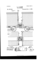
- Figure l is a side view of the ends of two cars coupled by the improvement, one of the car-trucks being higher than the other.
- Fig. 2 is aplan view of the same.
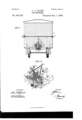
- Fig. 3 is an end elevation of a car and the improved couplings thereon and showing one means for the release of said coupling from the sides of the car.
- Fig. A is an enlarged perspective view of the forward end of the improved coupling, and
- Fig. 5 is an enlarged detached plan view of a hook-plate which is a feature of the invention.
- the improved car-coupling may be applied to cars of diderent styles for an automatic coupled connection of the same.
- the improvements are shown as attached to freight-cars of the box-bod y pattern.
- the coupling may be advantageously connected to a freight or passenger car, as shown in Figs. 1 and 3, by its location one at each end of the car-frame between two spaced longitudinal stringers A, that are near the transverse center of said frame, said stringers projecting sufficiently in advance of other portions of the car-frame to afford support for the improved coupling device.
- the improvement comprises two peculiarly connected coupling devices that may be separately or simultaneously used for connection of cars having the same.
- One portion of the duplex coupling consists of the elongated draw-bar 10, which is loosely supported to slide longitudinally a limited distance between the timbers A by the lugs 10, which oppositely project from the draw-bar between its ends and are loosely inserted in slots formed in the supporting timbers mentioned, one of said lugs and receiving-slot being shown on each car-frame illustrated in Fig. 1.
- the draw-bar 10 is further supported by the usual spring appliance 10*, (shown by dotted lines in Fig.
- a coupling-head block 12 is formed or secured on the upper side of the draw-bar 10 and draw-head ll of a suitable height and sub stantially rectangular in form, as plainly shown in Fig. 4.
- draw-head ll of a suitable height and sub stantially rectangular in form, as plainly shown in Fig. 4.
- a V-shaped formation 12 is produced on the head-block 12, which joins at its lower edge with forward projections 12, that'are integral portions of the head-block and slope downwardly and forwardly, as shown in Figs. 1 and 4.
- At each side of the guard-wall 12 At each side of the guard-wall 12,
- the head-block 12 is apertured for the reception of the similarly-sh aped draft-hooks 13.
- These draft-hooks two in number for each coupling, each consist of a preferably flat plate 13, straight on its side edges, and having a hook member 13 formed on the end that in service is forwardly projected.
- each draft-hook is undercut in its transverse wall, so as to project said member at a proper angle rearwardly and from the flat body 13 thereof.
- the end walls of the hook members 13 are sloped and nearly parallel with the undercut rear walls of said members, and that the inner corners 13 of'said hook formations are cut away; also that the inner faces 13 of the top edges of both hook members are convexly curved.
- the rear portion of each draft-hook occupies one of the apertures in the headblock 12, and is therein pivoted, so as to rock from a horizontal position, the said hookbodies being perforated, as at 13 in Fig. 5, when a vertical pivot-bolt is employed.
- the pivotal connection of the draft-hook with the head-block 12 may be produced by the insertion of a vertically-disposed pivot bolt 14 through aligned perforations in the block and hook-body, as is indicated by dotted lines in Figs. 1, 3, and 4, or the pivot-bolt may be laterally inserted in suitable perforations in the block and hook-body at the rear end of the latter, as also represented by dotted lines in Fig. 4 at 14
- the draft-hooks project in parallel planes from the head-block a short distance in advance of the guard-wall 2, and, as shown,one of said hooks has its member 13 on the top face of the hook-body, while the similar member of the other drafthook projects from the lower surface of the body 13.
- the draft-hook having its latching member 13 projected downwardly and rearwardly, is provided with a spring, which may be of a form similar to that shown at 15 in Fig. 4, said spring being designed to coact with the gravity of the draft-hook to insure its latching engagement with an upturned hook member 13f on another car-coupling, as will be further described.
- a tripping-dog 16 preferably in plate form, provided for releasing a hook which may engage with the draft-hook, whose member 13 is upwardly and rearwardly projected, and, as clearly shown in Figs. 1 and 4, said dog is pivoted on the head-block 12, so as to incline forwardly and downwardly toward the hook member mentioned, having sufficient length for effective service.
- One available means for lifting the hook on one side of the guardwall 12 and the tripping-dog on the other side of said wall, to effect a release of similar hooks on another coupling having the improvements and that is in coupled connection therewith comprises a transversely-supported rotary shaft 17 on the end wall of a car, such as B, and having a crank-handle 17 at each end, which handles are conveniently located at the sides of the car-body for rotary movement by a trainman.
- a chain or wire rope 18 is attached at one end, and at its other end is connected to the center of the doubled chain or rope 18, the ends of which are respectively secured to staples or other projections on the hook-body 13 and tripping-dog 16.
- a rotary shaft 19 is furnished, which is loosely stationed upright on the end of the car-body and projects above the same far enough to receive a hand-wheel 19, which is secured thereon.
- the upper end of the chain or other flexible connection 18 is loosely secured to the upright shaft 19, when the latter is supplied as a means for operating the draft-hooks 13, and upon rotation of said shaft it will be obvious that draft-strain will be applied to the chains 18 18 for release of two cars having the improved couplings that are in a coupled condition.
- the guard-wall 12" on each coupling is vertically perforated, and said perforations also extend down through the draw-heads 11, so that two coupling-pins 10 of like form may be utilized for holding an inserted coupling-link 20 of ordinary form in coupled connection with the adjacent heads of the draw bars, as indicated in Figs. 1 and 2.
- guard-wall 12 and sloped projections on the coupling-head block 12 at each side and joining with the base of the guard-wall contribute essentially to the efficient service of the latching draft-hooks 18, as the sloped walls Will lift a dropping hook on an approaching coupling to cause its latching engagement with the draft-hook, Whose hook member projects down and rearward, and the guard-wallserves to laterally guide an approaching hook mem her, so as to insure a proper latched engage ment with the coupling approached.
- the improved latchingcoupling can be raised on the draw-head 10, so as to bring the latching device upon a level with couplings that are of standard height, whereby cars of different standards of height may be provided with the improved couplings at but little additional expense.
- the improved coupler may advantageously be attached to the front end of a locomotive, and, if desired, may be dropped in a slot in the upper rear end of the cow-catcher on running trains and raised in position at will.
- the engineer can from his position on his engine by use of a lever uncouple the front end of his engine from a car, and by use of same lever can uncouple the rear end of his tender from a car.
- a draw bar having a head, oppositely arranged hooks pivoted on and projecting from said head, a dog pivoted over the hook, the bent end of which extends upwardly, said dog being adapted when lowered to lie flat against the body portion of said hook below the bent end thereof, a shaft mounted to turn on the car and flexible connections between said shaft, the said dog and the hook opposite said dog, substantially as set forth.
- a draw-head having a recess at each side, two hooks each having a perforated end, said hooks being arranged to play vertically and having their perforated ends located in said recesses, and pins arranged in the drawhead and extending vertically through the recesses therein and through the perforations in the ends of the hooks in said recesses, substantially as set forth.
Landscapes
- Engineering & Computer Science (AREA)
- Mechanical Engineering (AREA)
- Hooks, Suction Cups, And Attachment By Adhesive Means (AREA)
Description
AU e e h S e e h S 2 Hm I M CW .0 JR A A M d o M 0 W Nb. 547,333. Patented 001;. 1 1895.
FTIIHIIIIIIHHIIH llllllllllllllll'llllll WITNESSES."
ATTOHNE rs.
AN DREW B.GRANAM PHUTO-UNDVWASHINGTUKUQ 2 Sheets-Sheet 2.
K R A L O J A 9 1 .L 0 0 d nu +u H nu t a WITNESSES:
A TTOHN E Y 8.
AN DREW EGRAHAM. PHOTOUTKQWASIHNGTONJ C.
ANDREW JACKSON CLARK, or MADISON STATION, MISSISSIPPI.
CAR-COUPLING.
SPECIFICATION forming part of Letters Patent N 0. 547,333, dated October 1, 1895. Application filed July 3, 1395. Serial Not 54,843. (NomodeLl To all whom it may concern.-
Be it known that 1, ANDREW JACKSON CLARK, of Madison Station, in the county of Madison and State of Mississippi, have invented a new and Improved Car-Coupling, of which the following is a full, clear, and exact description.
This invention relates to an improved carcoupling of a class wherein interlocking hooks are provided wherewith to effect a coupled engagement of two cars.
The object of the invention is to produce such a car'coupling which will be of a very simple construction, strong and durable in use, and that will operate automatically and reliably to couple and retain cars in a coupled condition either on a straight track or on curves and whether the car-trucks are of the sameheight or vary in height.
A further object is to provide novel and effective means for the convenient release of cars coupled by the improvements, and which maybe operated from either side or top of the car; and afurther object of the invention is to effect a novel combination of a link-and-pincoupled draw-bar, springcushioned on the car, with the improved latching coupling device, whereby the link-and-pin coupling may be used when a car having the improved coupler comes in contact with a car not having the improved coupler.
The invention consists in the construction and combination of parts, as is hereinafter described, and indicated in the claims.
Reference is to be had to the accompanying drawings, forming a part of this specification, in which similar characters of reference indicate corresponding parts in all the views.
Figure l is a side view of the ends of two cars coupled by the improvement, one of the car-trucks being higher than the other. Fig. 2 is aplan view of the same. Fig. 3 is an end elevation of a car and the improved couplings thereon and showing one means for the release of said coupling from the sides of the car. Fig. A is an enlarged perspective view of the forward end of the improved coupling, and Fig. 5 is an enlarged detached plan view of a hook-plate which is a feature of the invention.
The improved car-coupling may be applied to cars of diderent styles for an automatic coupled connection of the same. For illustration, however, the improvements are shown as attached to freight-cars of the box-bod y pattern. The coupling may be advantageously connected to a freight or passenger car, as shown in Figs. 1 and 3, by its location one at each end of the car-frame between two spaced longitudinal stringers A, that are near the transverse center of said frame, said stringers projecting sufficiently in advance of other portions of the car-frame to afford support for the improved coupling device.
The improvement comprises two peculiarly connected coupling devices that may be separately or simultaneously used for connection of cars having the same. One portion of the duplex coupling consists of the elongated draw-bar 10, which is loosely supported to slide longitudinally a limited distance between the timbers A by the lugs 10, which oppositely project from the draw-bar between its ends and are loosely inserted in slots formed in the supporting timbers mentioned, one of said lugs and receiving-slot being shown on each car-frame illustrated in Fig. 1. The draw-bar 10 is further supported by the usual spring appliance 10*, (shown by dotted lines in Fig. 1,) the reduced rear portion of the draw-bar sliding through a transverse block between thetimbers A and having said spring mounted thereon, so as to be adapted for cushioningthe impinge of a forcible thrust received atthe front of the draw-bar in service. The'forward portion of the draw-bar 10.is suitably enlarged and chambered from thefront 'rearwardly to form an ordinary coupling-head 11 thereon, and, as shown in Figs. 1 and 2, the draw-bar and its head are projected in advance of the car-body B, to adapt it for the reception of the coacting coupling device, which will now be described. A coupling-head block 12 is formed or secured on the upper side of the draw-bar 10 and draw-head ll of a suitable height and sub stantially rectangular in form, as plainly shown in Fig. 4. At or near the. transverse center a V-shaped formation 12 is produced on the head-block 12, which joins at its lower edge with forward projections 12, that'are integral portions of the head-block and slope downwardly and forwardly, as shown in Figs. 1 and 4. At each side of the guard-wall 12,
as said formation is preferably termed, the head-block 12 is apertured for the reception of the similarly-sh aped draft-hooks 13. These draft-hooks, two in number for each coupling, each consist of a preferably flat plate 13, straight on its side edges, and having a hook member 13 formed on the end that in service is forwardly projected.
As clearly shown in Figs. 1 and 4, the hook portion 13 of each draft-hook is undercut in its transverse wall, so as to project said member at a proper angle rearwardly and from the flat body 13 thereof. It will also be seen that the end walls of the hook members 13 are sloped and nearly parallel with the undercut rear walls of said members, and that the inner corners 13 of'said hook formations are cut away; also that the inner faces 13 of the top edges of both hook members are convexly curved. The rear portion of each draft-hook occupies one of the apertures in the headblock 12, and is therein pivoted, so as to rock from a horizontal position, the said hookbodies being perforated, as at 13 in Fig. 5, when a vertical pivot-bolt is employed.
The pivotal connection of the draft-hook with the head-block 12 may be produced by the insertion of a vertically-disposed pivot bolt 14 through aligned perforations in the block and hook-body, as is indicated by dotted lines in Figs. 1, 3, and 4, or the pivot-bolt may be laterally inserted in suitable perforations in the block and hook-body at the rear end of the latter, as also represented by dotted lines in Fig. 4 at 14 The draft-hooks project in parallel planes from the head-block a short distance in advance of the guard-wall 2, and, as shown,one of said hooks has its member 13 on the top face of the hook-body, while the similar member of the other drafthook projects from the lower surface of the body 13. Preferably the draft-hook, having its latching member 13 projected downwardly and rearwardly, is provided with a spring, which may be of a form similar to that shown at 15 in Fig. 4, said spring being designed to coact with the gravity of the draft-hook to insure its latching engagement with an upturned hook member 13f on another car-coupling, as will be further described. There is a tripping-dog 16, preferably in plate form, provided for releasing a hook which may engage with the draft-hook, whose member 13 is upwardly and rearwardly projected, and, as clearly shown in Figs. 1 and 4, said dog is pivoted on the head-block 12, so as to incline forwardly and downwardly toward the hook member mentioned, having sufficient length for effective service. One available means for lifting the hook on one side of the guardwall 12 and the tripping-dog on the other side of said wall, to effect a release of similar hooks on another coupling having the improvements and that is in coupled connection therewith, comprises a transversely-supported rotary shaft 17 on the end wall of a car, such as B, and having a crank-handle 17 at each end, which handles are conveniently located at the sides of the car-body for rotary movement by a trainman. At or near the longitudinal center of the rotatable shaft 17 a chain or wire rope 18 is attached at one end, and at its other end is connected to the center of the doubled chain or rope 18, the ends of which are respectively secured to staples or other projections on the hook-body 13 and tripping-dog 16.
By the described arrangement of parts it will be seen that if the shaft is rotated the attached end of the flexible connection 18 will be wrapped on said shaft, the draft-hook 13 directly connected with the shaft will be upwardly rocked, andthe dog or trippingplate 16 similarly moved, and as the free end of the latter-named part is projected below a hook member 13" of a mating coupling that is engaged with the upwardly and rearwardly inclined hook member of the draft-hook having the dog it will be evident that the dog 16 will, when'drawn upward, lift the depending hook member beneath which it projects, and so release two of the improved couplings from coupled connection with each other. A springcatch 17 (see Fig. 2) is preferably used to retain the chain 18 in wrapped condition on the shaft 17, the catch being secured on one side of the car-body B, so as to project below the crank-arm of the rotary shaft and prevent its rotation by accident, the resilience of the catch permitting the manual rotation'of the shaft when required.
In case it is desired to release two cars having the improvements by a manipulation of the releasing device from the roof of one car, then a rotary shaft 19 is furnished, which is loosely stationed upright on the end of the car-body and projects above the same far enough to receive a hand-wheel 19, which is secured thereon. The upper end of the chain or other flexible connection 18 is loosely secured to the upright shaft 19, when the latter is supplied as a means for operating the draft-hooks 13, and upon rotation of said shaft it will be obvious that draft-strain will be applied to the chains 18 18 for release of two cars having the improved couplings that are in a coupled condition.
To adapt the draw-bars 10 and the drawheads 11 on two couplings of the improved construction 'to serve as linkand-pin coup lings, the guard-wall 12" on each coupling is vertically perforated, and said perforations also extend down through the draw-heads 11, so that two coupling-pins 10 of like form may be utilized for holding an inserted coupling-link 20 of ordinary form in coupled connection with the adjacent heads of the draw bars, as indicated in Figs. 1 and 2.
In operation it will be apparent that if two cars having the improvements are brought together the hooks 13 of the couplings will antomatically engage In pairs, and from their IIO peculiar construction will maintain a coupled condition, either on a straight track or on a sharp curve of the same, the curved edges of the hook members 13 and removal of the inner corners from said hook members conducing to the efficient operation of the improved car-couplings under all conditions of service. Furthermore, the construction is such that should either of the hooks 13 become broken an ordinary coupling-link may be inserted in the recess in place thereof and held in place by means of the pin 14. The provision of the guard-wall 12 and sloped projections on the coupling-head block 12 at each side and joining with the base of the guard-wall contribute essentially to the efficient service of the latching draft-hooks 18, as the sloped walls Will lift a dropping hook on an approaching coupling to cause its latching engagement with the draft-hook, Whose hook member projects down and rearward, and the guard-wallserves to laterally guide an approaching hook mem her, so as to insure a proper latched engage ment with the coupling approached. The provision of the ordinary draw-bar 10 and draw-head 11 thereon facilitates the support and proper connection of the main automatic hook-coupling with the car-frame, and also furnishes means for a coupled connection of a car having only the common link-and-pin car-couplings.
As clearly shown in Fig. 1, if the frame of one of the cars is nearer the track'rails than the other the improved latchingcoupling can be raised on the draw-head 10, so as to bring the latching device upon a level with couplings that are of standard height, whereby cars of different standards of height may be provided with the improved couplings at but little additional expense.
The improved coupler may advantageously be attached to the front end of a locomotive, and, if desired, may be dropped in a slot in the upper rear end of the cow-catcher on running trains and raised in position at will. The engineer can from his position on his engine by use of a lever uncouple the front end of his engine from a car, and by use of same lever can uncouple the rear end of his tender from a car.
Having thus described my invention, I claim as new and desire to secure by Letters Patent 1. The combination, with a spring-pressed draw-bar having a chambered head at the front, of a coupling head block projecting upwardly from the top of the drawbar at its front, and having a V-shaped guard wall near its transverse center, joined to sloped projections at each side thereof, two draft hooks, the hook members of which project from the top and bottom sides of the draft hook bodies, a tripping dog hung from the front side of the coupling head block above the hook member that projects upward and rearward, and flexible connections engagingthe hook having the depending hook and also connected with the tripping dog, and means for operating the flexible connections from a car, the locomotive or the ground, substantially as described.
2. In a car coupling, the combination of a draw bar having a head, oppositely arranged hooks pivoted on and projecting from said head, a dog pivoted over the hook, the bent end of which extends upwardly, said dog being adapted when lowered to lie flat against the body portion of said hook below the bent end thereof, a shaft mounted to turn on the car and flexible connections between said shaft, the said dog and the hook opposite said dog, substantially as set forth.
3. In a car coupling, the combination of a draw-head having a recess at each side, two hooks each having a perforated end, said hooks being arranged to play vertically and having their perforated ends located in said recesses, and pins arranged in the drawhead and extending vertically through the recesses therein and through the perforations in the ends of the hooks in said recesses, substantially as set forth.
ANDREW J AOKSON CLARK.
Witnesses:
DAVID L. PHARES, FINLEY J ONES.
Publications (1)
| Publication Number | Publication Date |
|---|---|
| US547333A true US547333A (en) | 1895-10-01 |
Family
ID=2616076
Family Applications (1)
| Application Number | Title | Priority Date | Filing Date |
|---|---|---|---|
| US547333D Expired - Lifetime US547333A (en) | Car-coupling |
Country Status (1)
| Country | Link |
|---|---|
| US (1) | US547333A (en) |
-
0
- US US547333D patent/US547333A/en not_active Expired - Lifetime
Similar Documents
| Publication | Publication Date | Title |
|---|---|---|
| US433374A (en) | Car-coupling | |
| US335611A (en) | Jambs franklin moorman | |
| US358182A (en) | Car-coupling | |
| US166717A (en) | Improvement in car couplings | |
| US163897A (en) | Improvement in car-couplings | |
| US560437A (en) | Car-coupling | |
| US550732A (en) | Car-coupling | |
| US574741A (en) | Car-coupling | |
| US173758A (en) | Improvement in car-couplings | |
| US558620A (en) | Car-coupling | |
| US472418A (en) | Car-coupling | |
| US329493A (en) | Car-coupling | |
| US356932A (en) | fennell | |
| US262809A (en) | Car-coupling | |
| US184084A (en) | Improvement in car-couplings | |
| US190984A (en) | Improvement in car-couplings | |
| US594315A (en) | James simpson bartley | |
| US395750A (en) | Car-coupling | |
| US276229A (en) | digkebson | |
| US180016A (en) | Improvement in car-couplings | |
| US238425A (en) | Car-coupling | |
| US342658A (en) | Brook | |
| US577464A (en) | Car-coupling | |
| US199173A (en) | Improvement in car-couplings | |
| US336791A (en) | Car-coupling |