US5470200A - Guide vanes for axial fans - Google Patents
Guide vanes for axial fans Download PDFInfo
- Publication number
- US5470200A US5470200A US08/175,356 US17535694A US5470200A US 5470200 A US5470200 A US 5470200A US 17535694 A US17535694 A US 17535694A US 5470200 A US5470200 A US 5470200A
- Authority
- US
- United States
- Prior art keywords
- guide vanes
- arrangement
- fan
- alternate
- axial
- Prior art date
- Legal status (The legal status is an assumption and is not a legal conclusion. Google has not performed a legal analysis and makes no representation as to the accuracy of the status listed.)
- Expired - Fee Related
Links
- 238000006073 displacement reaction Methods 0.000 claims description 28
- 230000000694 effects Effects 0.000 description 6
- 230000007423 decrease Effects 0.000 description 2
- 238000005259 measurement Methods 0.000 description 2
- 238000010586 diagram Methods 0.000 description 1
- 238000009828 non-uniform distribution Methods 0.000 description 1
- 238000001228 spectrum Methods 0.000 description 1
- 238000009827 uniform distribution Methods 0.000 description 1
Images


Classifications
-
- F—MECHANICAL ENGINEERING; LIGHTING; HEATING; WEAPONS; BLASTING
- F04—POSITIVE - DISPLACEMENT MACHINES FOR LIQUIDS; PUMPS FOR LIQUIDS OR ELASTIC FLUIDS
- F04D—NON-POSITIVE-DISPLACEMENT PUMPS
- F04D29/00—Details, component parts, or accessories
- F04D29/66—Combating cavitation, whirls, noise, vibration or the like; Balancing
- F04D29/661—Combating cavitation, whirls, noise, vibration or the like; Balancing especially adapted for elastic fluid pumps
-
- F—MECHANICAL ENGINEERING; LIGHTING; HEATING; WEAPONS; BLASTING
- F04—POSITIVE - DISPLACEMENT MACHINES FOR LIQUIDS; PUMPS FOR LIQUIDS OR ELASTIC FLUIDS
- F04D—NON-POSITIVE-DISPLACEMENT PUMPS
- F04D29/00—Details, component parts, or accessories
- F04D29/40—Casings; Connections of working fluid
- F04D29/52—Casings; Connections of working fluid for axial pumps
- F04D29/54—Fluid-guiding means, e.g. diffusers
- F04D29/541—Specially adapted for elastic fluid pumps
- F04D29/542—Bladed diffusers
- F04D29/544—Blade shapes
-
- F—MECHANICAL ENGINEERING; LIGHTING; HEATING; WEAPONS; BLASTING
- F04—POSITIVE - DISPLACEMENT MACHINES FOR LIQUIDS; PUMPS FOR LIQUIDS OR ELASTIC FLUIDS
- F04D—NON-POSITIVE-DISPLACEMENT PUMPS
- F04D29/00—Details, component parts, or accessories
- F04D29/66—Combating cavitation, whirls, noise, vibration or the like; Balancing
- F04D29/661—Combating cavitation, whirls, noise, vibration or the like; Balancing especially adapted for elastic fluid pumps
- F04D29/666—Combating cavitation, whirls, noise, vibration or the like; Balancing especially adapted for elastic fluid pumps by means of rotor construction or layout, e.g. unequal distribution of blades or vanes
Definitions
- the following invention relates to a guide vane arrangement for axial fans, intended to convert the rotational component in the gas flow velocity after passage through the impeller into a substantially axial velocity, the arrangement including a ring of guide vanes disposed downstream of the fan and in spaced relationship therewith.
- the gas flow downstream of the impeller of an axial fan normally rotates.
- the rotational energy can be translated into useful energy by a guide vane arrangement on the outlet side of the fan, this arrangement converting the rotational velocity to an axial velocity component.
- the pressure is raised in this way, and the efficiency of the fan increases. Normally, however, the sound level also increases at the same time.
- the sound from a fan comprises tonal components, i.e. tones with discrete frequencies and a wide band noise with a continuous frequency spectrum.
- tonal components i.e. tones with discrete frequencies and a wide band noise with a continuous frequency spectrum.
- a guide vane is described in the Swedish patent 8802136-5, which has improved aerodynamic and acoustic properties.
- the object of the present invention is to lower individual, disturbing tones in the fan sound, as well as lower the general noise level in a simple way.
- the first-mentioned object is achieved with a guide vane ring of the kind mentioned in the introduction, and with characteristics disclosed hereinbelow 1.
- the second object is achieved by a further development of the inventive guide vane arrangement, in which alternate guide vanes are axially displaced relative the remaining ones, so that alternate guide vanes are at a first axial distance from the fan, and the remainder at a second axial distance, simultaneously as the guide vanes are non-uniformly distributed in the guide vane ring circumference.
- alternate guide vanes are displaced in the circumferential direction relative to the remaining guide vanes with a constant displacement so that the distance in the circumferential direction between juxtaposed guide vanes alternates between two given values.
- This arrangement reduces both individual tones and the general wide band noise from the fan.
- this combination of axial displacement and circumferential displacement of the guide vanes provides improved efficiency of the fan, compared with the case using a guide vane arrangement with only axial displacement of the guide vanes, or only rotation of the vanes in the circumferential direction.
- the axial displacement of the guide vanes is in the interval 0,4-0,7 l/l ch , preferably 0,5 l/l ch , where l denotes the magnitude of the displacement and l ch the length along the guide vane.
- the displacement in the circumferential direction is in the interval 5°-15°, and is preferably 10°.
- the guide vane ring arrangement is divided into two rings axially in tandem, alternate guide vanes being carried by one ring and the other guide vanes by the other ring, the rings being axially displaceable relative to each other or radially rotatable relative each other about a common axis. It is thus possible to adjust the guide vane arrangement in a simple way to achieve optimum conditions.
- the guide vanes are designed with a web configuration between the radially outer and inner portions of the guide vane such that the arcuate length along the single-curved guide vane at the level of the web is shorter than at said mentioned outer and inner portions.
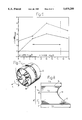
- FIG. 1 illustrates the effect on the sound level from the fan when alternate guide vanes are displaced in the circumferential direction in accordance with prior art
- FIG. 2 illustrates an axial fan with guide vanes arranged downstream of the fan
- FIG. 3 schematically illustrates five different guide vane arrangements which include: a) guide vanes arranged uniformly according to the prior art, b) alternate guide vanes displaced in the circumferential direction of the guide vane ring according to the prior art, c) alternate guide vanes axially displaced in accordance with the invention, d) a combination of axial displacement and rotation of the guide vane ring in a circumferential direction in accordance with the invention, e) the combination of the displacement in the circumferential direction and the provision of a cut-out in alternate guide vanes in accordance with the invention;
- FIG. 4 illustrates the effect on the sound from the fan resulting from the axial displacement of the alternate guide vanes in accordance with the operational case c) in FIG. 3;
- FIG. 5 illustrates the effect on the sound level from the fan of the combination of axial displacement and displacement of the guide vanes in the circumferential direction of the guide vane ring according to the operational case d) in FIG. 3
- FIG. 6 illustrates the reduction of sound in the tone at the blade frequency as a function of the rotation in the circumferential direction for a given axial displacement of the guide vanes
- FIG. 7 illustrates an embodiment of the arrangement where two guide vane rings are used.
- FIG. 8 illustrates a particular guide vane configuration
- FIG. 2 illustrates an axial fan installed in a duct 4 and having a guide vane ring 2 arranged in spaced relationship with, and downstream of the impeller 1.
- the number of guide vanes is preferably between 0.5 and 2.1 times the number of blades in the impeller.
- FIG. 1 the effects on the sound from a fan with guide vane arrangements according to the principles shown in FIGS. 3a and 3b are compared under the conditions given above. It will be seen from FIG. 1 that displacement Lw (dB) of alternate guide vanes in the circumferential direction of the guide vane ring according to FIG. 3b results in a heavy decrease of a tone at the blade frequency f (Hz) of 160 Hz, while there is an increase in the noise level for frequencies over about 500 Hz.
- FIG. 4 compares the effect on the sound level f (Hz) of the guide vane arrangements according to FIGS. 3a and 3c. It will be seer that there is a considerable lowering of the tone at the blade frequency f (Hz) 160 Hz of about 3.5 dB, while there is an increase o the wide band high frequency noise over about 500 Hz.
- the operational conditions are the same as for FIG. 1.
- FIG. 5 the sound levels for the guide vane arrangements according to FIGS. 3a and 3d are compared.
- Rotation in the circumferential direction amounts to 10°.
- FIG. 6 there is illustrated the attenuation ⁇ L W at the blade frequency, as a function of the rotation B of alternate guide vanes in a guide vane arrangement where the alternate guide vane is also axially diplaced by half the length of the guide vane.
- FIG. 3e Another acoustically advantageous embodiment of the apparatus according to the invention is illustrated in FIG. 3e.
- a portion of the end part facing towards the impeller of alternate guide vanes is concave, so that the forward edge of these guide vanes is at a first axial distance from the impeller and the remainder at a second axial distance.
- the guide vanes are non-uniformly distributed round the circumference of the ring.
- FIG. 7 there is illustrated a further advantageous embodiment of the guide vane ring 2 in the apparatus in accordance with the invention.
- the ring 2 includes two rings 20,22 mounted on a common shaft.
- alternate guide vanes are carried by one of the two rings and the other by the other ring.
- the two rings are mutually axially displacable and relatively rotatable about the common shaft.
- FIG. 8 illustrates an embodiment of a guide vane 6, which is found to be advantageous in the arrangement according to the invention.
- the end portion of the guide vane 10, which is intended to face towards the impeller has an edge 10 with a parabola-like configuration, so that between the inner and outer longitudinal edges 12 and 14 of the guide vane 6 there is a web with a shorter length L 2 along the guide vane than said edges L 1 and L 3 , respectively.
- the guide vane has a straight back edge 16. If the height of the web from the inner longitudinal edge 12 is denoted by H 1 and the total height of the guide vane by H 2 the position of the web is determined by the condition:
Landscapes
- Engineering & Computer Science (AREA)
- Mechanical Engineering (AREA)
- General Engineering & Computer Science (AREA)
- Physics & Mathematics (AREA)
- Geometry (AREA)
- Structures Of Non-Positive Displacement Pumps (AREA)
- Control Of Turbines (AREA)
Abstract
A guide vane arrangement for axial fans, intended to translate the rotational component of the gas flow velocity after passage through the impeller (1) into a substantially axial velocity, including a ring (2) of guide vanes disposed downstream of the fan and in spaced relationship therewith. Alternate guide vanes are axially displaced with respect to the remaining ones, so that alternate guide vanes are at a first axial distance from the fan and the remainder are at a second axial distance from the fan. As an alternative, alternate guide vanes have a portion of the end part facing towards the fan removed, so that the forward edge of alternate guide vanes is at a first distance from the fan and the remaining guide vanes are at a second axial distance, and the guide vanes are non-uniformly distributed along the periphery of the ring.
Description
The following invention relates to a guide vane arrangement for axial fans, intended to convert the rotational component in the gas flow velocity after passage through the impeller into a substantially axial velocity, the arrangement including a ring of guide vanes disposed downstream of the fan and in spaced relationship therewith.
The gas flow downstream of the impeller of an axial fan normally rotates. The rotational energy can be translated into useful energy by a guide vane arrangement on the outlet side of the fan, this arrangement converting the rotational velocity to an axial velocity component. The pressure is raised in this way, and the efficiency of the fan increases. Normally, however, the sound level also increases at the same time.
The sound from a fan comprises tonal components, i.e. tones with discrete frequencies and a wide band noise with a continuous frequency spectrum. Considerable efforts have been made primarily to lower the tonal components, by a suitable arrangement and embodiment of guide vanes on the output side of the fan.
It is accordingly a general understanding that the noise generated decreases with increasing distance between the impeller and guide vanes, see M. J. Benzakein, J. Acoust. Soc. Am. 51 (1972), 1427-1438 and W. Neise, Proc. INTER-NOISE 1988, pp 767-776. It has been found, however, this is not always applicable.
A guide vane is described in the Swedish patent 8802136-5, which has improved aerodynamic and acoustic properties.
It has also been found earlier that a non-uniform distribution of the guide vanes in the ring of guide vanes can give rise to certain acoustic improvements, although it has been found that large deviations from a uniform distribution of the guide vanes give rise to aerodynamic problems.
It is also known that certain acoustic characteristics can be improved by a portion being cut out from alternate guide vanes in their the forward portions.
FIG. 1 illustrates how the strength in an individual tone can be reduced by displacing the guide vanes in the circumferential direction of the guide vane ring. It will also be seen from the same figure that the noise at higher frequencies over about 500 Hz also increases at the same time. The measurement has been made for a fan R.P.M. of n=970 and a displacement of alternate guide vanes of β=10° and β=0°.
The object of the present invention is to lower individual, disturbing tones in the fan sound, as well as lower the general noise level in a simple way.
The first-mentioned object is achieved with a guide vane ring of the kind mentioned in the introduction, and with characteristics disclosed hereinbelow 1.
The second object is achieved by a further development of the inventive guide vane arrangement, in which alternate guide vanes are axially displaced relative the remaining ones, so that alternate guide vanes are at a first axial distance from the fan, and the remainder at a second axial distance, simultaneously as the guide vanes are non-uniformly distributed in the guide vane ring circumference. Preferably, alternate guide vanes are displaced in the circumferential direction relative to the remaining guide vanes with a constant displacement so that the distance in the circumferential direction between juxtaposed guide vanes alternates between two given values. This arrangement reduces both individual tones and the general wide band noise from the fan. In addition, this combination of axial displacement and circumferential displacement of the guide vanes provides improved efficiency of the fan, compared with the case using a guide vane arrangement with only axial displacement of the guide vanes, or only rotation of the vanes in the circumferential direction.
By the combination of measures according to this further development of the apparatus in accordance with the invention, there are achieved highly important advantages, both with respect to acoustics and efficiency, considerably exceeding the effects achieved by the individual measures of axial displacement or circumferential rotation of the guide vanes.
In accordance with another advantageous embodiment of the inventive apparatus, the axial displacement of the guide vanes is in the interval 0,4-0,7 l/lch, preferably 0,5 l/lch, where l denotes the magnitude of the displacement and lch the length along the guide vane.
In accordance with yet another advantageous embodiment, the displacement in the circumferential direction is in the interval 5°-15°, and is preferably 10°.
In accordance with a further advantageous embodiment of the apparatus in accordance with the invention, the guide vane ring arrangement is divided into two rings axially in tandem, alternate guide vanes being carried by one ring and the other guide vanes by the other ring, the rings being axially displaceable relative to each other or radially rotatable relative each other about a common axis. It is thus possible to adjust the guide vane arrangement in a simple way to achieve optimum conditions.
In accordance with a further advantageous embodiment of the invention, in the portion facing towards the impeller the guide vanes are designed with a web configuration between the radially outer and inner portions of the guide vane such that the arcuate length along the single-curved guide vane at the level of the web is shorter than at said mentioned outer and inner portions.
Emodiments of the arrangements in accordance with the invention, selected as examples, will now be described in greater detail and with reference to the accompanying drawings, wherein
FIG. 1 illustrates the effect on the sound level from the fan when alternate guide vanes are displaced in the circumferential direction in accordance with prior art;
FIG. 2 illustrates an axial fan with guide vanes arranged downstream of the fan;
FIG. 3 schematically illustrates five different guide vane arrangements which include: a) guide vanes arranged uniformly according to the prior art, b) alternate guide vanes displaced in the circumferential direction of the guide vane ring according to the prior art, c) alternate guide vanes axially displaced in accordance with the invention, d) a combination of axial displacement and rotation of the guide vane ring in a circumferential direction in accordance with the invention, e) the combination of the displacement in the circumferential direction and the provision of a cut-out in alternate guide vanes in accordance with the invention;
FIG. 4 illustrates the effect on the sound from the fan resulting from the axial displacement of the alternate guide vanes in accordance with the operational case c) in FIG. 3;
FIG. 5 illustrates the effect on the sound level from the fan of the combination of axial displacement and displacement of the guide vanes in the circumferential direction of the guide vane ring according to the operational case d) in FIG. 3
FIG. 6 illustrates the reduction of sound in the tone at the blade frequency as a function of the rotation in the circumferential direction for a given axial displacement of the guide vanes;
FIG. 7 illustrates an embodiment of the arrangement where two guide vane rings are used and
FIG. 8 illustrates a particular guide vane configuration.
FIG. 2 illustrates an axial fan installed in a duct 4 and having a guide vane ring 2 arranged in spaced relationship with, and downstream of the impeller 1. The number of guide vanes is preferably between 0.5 and 2.1 times the number of blades in the impeller.
In FIG. 1 the effects on the sound from a fan with guide vane arrangements according to the principles shown in FIGS. 3a and 3b are compared under the conditions given above. It will be seen from FIG. 1 that displacement Lw (dB) of alternate guide vanes in the circumferential direction of the guide vane ring according to FIG. 3b results in a heavy decrease of a tone at the blade frequency f (Hz) of 160 Hz, while there is an increase in the noise level for frequencies over about 500 Hz.
FIG. 4 compares the effect on the sound level f (Hz) of the guide vane arrangements according to FIGS. 3a and 3c. It will be seer that there is a considerable lowering of the tone at the blade frequency f (Hz) 160 Hz of about 3.5 dB, while there is an increase o the wide band high frequency noise over about 500 Hz. The operational conditions are the same as for FIG. 1.
In FIG. 5 the sound levels for the guide vane arrangements according to FIGS. 3a and 3d are compared. A surprising result will be seen from this figure in that the combination of axial displacement and rotation (i.e., being out of alignment) in the circumferential direction of the ring of alternate guide vanes leads to a reduction of the sound level over the entire frequency range, compared with a conventional guide vane arrangement with uniformly distributed guide vanes. FIG. 5 demonstrates that both discrete tones at lower frequencies and the wide band high frequency noise are antenuated in an embodiment according to FIG. 3d. The axial displacement of the guide vanes is l/lch =0,5, where l denotes the magnitude of the displacement and lch the length along the guide vane, i.e. the displacement amounts to half the length of the guide vane. Rotation in the circumferential direction amounts to 10°. The curves are measured for a fan R.P.M. of n=970.
In FIG. 6 there is illustrated the attenuation ΔLW at the blade frequency, as a function of the rotation B of alternate guide vanes in a guide vane arrangement where the alternate guide vane is also axially diplaced by half the length of the guide vane. The graphs are shown for two different revolutionary velocities of the fan, namely n=970 rpm, and n=1430 rpm. This diagram shows that a considerable reduction of tonal components is achieved in the angle range 5°-15° for the axial displacement of the guide vanes that is under consideration. Measurements have also shown that some improvement in aerodynamic efficiency of the fan in the region where the best sound attenuation is achieved.
Another acoustically advantageous embodiment of the apparatus according to the invention is illustrated in FIG. 3e. In this embodiment a portion of the end part facing towards the impeller of alternate guide vanes is concave, so that the forward edge of these guide vanes is at a first axial distance from the impeller and the remainder at a second axial distance. In addition, the guide vanes are non-uniformly distributed round the circumference of the ring.
In FIG. 7 there is illustrated a further advantageous embodiment of the guide vane ring 2 in the apparatus in accordance with the invention. The ring 2 includes two rings 20,22 mounted on a common shaft. Here, alternate guide vanes are carried by one of the two rings and the other by the other ring. The two rings are mutually axially displacable and relatively rotatable about the common shaft. With this embodiment of the guide vane ring 2 there is enabled in a simple way the axial displacement and rotation along the circumference of the guide vanes relative each other so that desired properties are achieved.
FIG. 8 illustrates an embodiment of a guide vane 6, which is found to be advantageous in the arrangement according to the invention. The end portion of the guide vane 10, which is intended to face towards the impeller has an edge 10 with a parabola-like configuration, so that between the inner and outer longitudinal edges 12 and 14 of the guide vane 6 there is a web with a shorter length L2 along the guide vane than said edges L1 and L3, respectively. The guide vane has a straight back edge 16. If the height of the web from the inner longitudinal edge 12 is denoted by H1 and the total height of the guide vane by H2 the position of the web is determined by the condition:
0.4<H.sub.1 /H.sub.2 <0.9,
and preferably
0.5<H.sub.1 /H.sub.2 <0.8
Claims (11)
1. Guide vane arrangement of axial fans, the arrangement translating the rotational component of the gas flow velocity after passage through the impeller (1) into a substantially axial velocity, which comprises:
a ring (2) of guide vanes arranged downstream of the impeller and in spaced relationship therewith, wherein alternate guide vanes with an edge facing the impeller are axially displaced relative to remaining guide vanes and wherein alternate guide vanes are located a first axial distance from the fan and the remaining guide vanes are located at a second axial distance from the fan, and the guide vanes are non-uniformly distributed along a circumference of the ring.
2. Arrangement according to claim 1, wherein a portion of an end part facing towards the impeller (1) of the alternate guide vanes is concave so that the forward edge of said guide vanes is at a first axial distance from the fan and the remainder of the guide vanes is at said second axial distance from the fan.
3. Arrangement as claimed in claim 2, wherein the alternate guide vanes are out of alignment in the circumferential direction relative the remaining guide vanes, with a constant displacement, so that the distance in the circumferential direction between adjacent guide vanes varies between two given values.
4. Arrangement as claimed in claims 1 or 2, wherein the axial displacement between the alternate guide vanes and the remaining guide vanes is in an interval of l/lch =0.40-0.7 where l denotes the magnitude of the displacement and lch denotes the length of the guide vane.
5. Arrangement as claimed in claim 2, wherein the angular displacement in a circumferential direction has an interval of 5°-15°.
6. Arrangement as claimed in claim 1, wherein the guide vane ring (2) comprises first and second rings (20, 22) positioned axially in tandem wherein said alternate guide vanes are carried by said first rings and the remaining guide vanes by said second ring, and wherein said first and second rings are mutually axially displaceable and/or radially rotatable relative each other about a common axis.
7. Arrangement as claimed in claim 1, wherein the guide vanes, in a part facing towards the fan, are formed with a web between radially outer and inner portions of the guide vanes, and wherein an arcuate length at the level of the web is shorter than at said outer and inner portions.
8. Arrangement as claimed in claim 1, wherein the number of guide vanes is between 0.5 and 2.1 times the number of blades of the impeller.
9. Arrangement as claimed in claim 4, wherein l/lch =0.5.
10. Arrangement as claimed in claim 3, wherein the angular displacement in the circumferential direction has an interval of 10°.
11. Arrangement as claimed in claim 4, wherein the angular displacement in the circumferential direction has an interval of 10°.
Applications Claiming Priority (3)
| Application Number | Priority Date | Filing Date | Title |
|---|---|---|---|
| SE9102150A SE500471C2 (en) | 1991-07-09 | 1991-07-09 | Guide device in an axial fan |
| SE9102150 | 1991-07-09 | ||
| PCT/SE1992/000481 WO1993001415A1 (en) | 1991-07-09 | 1992-06-26 | Guide vane means |
Publications (1)
| Publication Number | Publication Date |
|---|---|
| US5470200A true US5470200A (en) | 1995-11-28 |
Family
ID=20383309
Family Applications (1)
| Application Number | Title | Priority Date | Filing Date |
|---|---|---|---|
| US08/175,356 Expired - Fee Related US5470200A (en) | 1991-07-09 | 1992-06-26 | Guide vanes for axial fans |
Country Status (13)
| Country | Link |
|---|---|
| US (1) | US5470200A (en) |
| EP (1) | EP0680563B1 (en) |
| JP (1) | JPH06509150A (en) |
| KR (1) | KR100229693B1 (en) |
| AU (1) | AU657353B2 (en) |
| CA (1) | CA2111103A1 (en) |
| DE (1) | DE69224853T2 (en) |
| DK (1) | DK0680563T3 (en) |
| ES (1) | ES2113951T3 (en) |
| FI (1) | FI102310B (en) |
| RU (1) | RU2101576C1 (en) |
| SE (1) | SE500471C2 (en) |
| WO (1) | WO1993001415A1 (en) |
Cited By (11)
| Publication number | Priority date | Publication date | Assignee | Title |
|---|---|---|---|---|
| US6471473B1 (en) | 2000-10-17 | 2002-10-29 | Rule Industries, Inc. | Marine in bilge blower |
| FR2824597A1 (en) * | 2001-05-11 | 2002-11-15 | Snecma Moteurs | Method for reducing vibrations in rotor-stator structure comprises a rotor/stator structure to changes the natural frequency of vibration |
| US6540478B2 (en) * | 2000-10-27 | 2003-04-01 | Mtu Aero Engines Gmbh | Blade row arrangement for turbo-engines and method of making same |
| US6609887B2 (en) * | 2000-05-05 | 2003-08-26 | Valeo Thermique Moteur | Fan for a motor vehicle, equipped with guide vanes |
| WO2007028910A1 (en) | 2005-09-09 | 2007-03-15 | Groupe Leader Sa | Fire-fighting fan including an air stream rectifier |
| US20090169371A1 (en) * | 2005-11-29 | 2009-07-02 | Ishikawajima-Harima Heavy Industries Co., Ltd. | Stator cascade of turbo type fluid machine |
| US9869191B2 (en) | 2012-10-09 | 2018-01-16 | United Technologies Corporation | Geared low fan pressure ratio fan exit guide vane stagger angle |
| US20180334916A1 (en) * | 2017-05-22 | 2018-11-22 | General Electric Company | Method and system for leading edge auxiliary turbine vanes |
| US10883515B2 (en) | 2017-05-22 | 2021-01-05 | General Electric Company | Method and system for leading edge auxiliary vanes |
| US11067309B2 (en) * | 2016-06-08 | 2021-07-20 | Ziehl-Abegg Se | Ventilator unit |
| CN114645865A (en) * | 2020-12-18 | 2022-06-21 | 日本电产株式会社 | Series axial fan |
Families Citing this family (3)
| Publication number | Priority date | Publication date | Assignee | Title |
|---|---|---|---|---|
| US5961970A (en) | 1993-10-29 | 1999-10-05 | Pharmos Corporation | Submicron emulsions as vaccine adjuvants |
| GB2401654B (en) * | 2003-05-14 | 2006-04-19 | Rolls Royce Plc | A stator vane assembly for a turbomachine |
| DE102010002395B4 (en) * | 2010-02-26 | 2017-10-19 | Rolls-Royce Deutschland Ltd & Co Kg | Turbofan engine with guide vanes and support struts arranged in the bypass duct |
Citations (6)
| Publication number | Priority date | Publication date | Assignee | Title |
|---|---|---|---|---|
| US821347A (en) * | 1904-04-21 | 1906-05-22 | Jens William Ogidius Elling | Fractional-supply steam and gas turbine. |
| US2839239A (en) * | 1954-06-02 | 1958-06-17 | Edward A Stalker | Supersonic axial flow compressors |
| FR1200484A (en) * | 1958-06-26 | 1959-12-22 | Alsthom Cgee | Water drainage device in steam turbines |
| US3883264A (en) * | 1971-04-08 | 1975-05-13 | Gadicherla V R Rao | Quiet fan with non-radial elements |
| US5152661A (en) * | 1988-05-27 | 1992-10-06 | Sheets Herman E | Method and apparatus for producing fluid pressure and controlling boundary layer |
| US5246339A (en) * | 1988-06-08 | 1993-09-21 | Abb Flakt Ab | Guide vane for an axial fan |
Family Cites Families (4)
| Publication number | Priority date | Publication date | Assignee | Title |
|---|---|---|---|---|
| US3747343A (en) * | 1972-02-10 | 1973-07-24 | United Aircraft Corp | Low noise prop-fan |
| US4720239A (en) * | 1982-10-22 | 1988-01-19 | Owczarek Jerzy A | Stator blades of turbomachines |
| US4981414A (en) * | 1988-05-27 | 1991-01-01 | Sheets Herman E | Method and apparatus for producing fluid pressure and controlling boundary layer |
| SE461112B (en) * | 1988-06-08 | 1990-01-08 | Flaekt Ab | LED LIGHT SHOWS AN AXIAL FLAT |
-
1991
- 1991-07-09 SE SE9102150A patent/SE500471C2/en not_active IP Right Cessation
-
1992
- 1992-06-26 EP EP92915625A patent/EP0680563B1/en not_active Expired - Lifetime
- 1992-06-26 ES ES92915625T patent/ES2113951T3/en not_active Expired - Lifetime
- 1992-06-26 RU RU94015165/06A patent/RU2101576C1/en not_active IP Right Cessation
- 1992-06-26 AU AU23312/92A patent/AU657353B2/en not_active Ceased
- 1992-06-26 US US08/175,356 patent/US5470200A/en not_active Expired - Fee Related
- 1992-06-26 DK DK92915625T patent/DK0680563T3/en active
- 1992-06-26 WO PCT/SE1992/000481 patent/WO1993001415A1/en not_active Ceased
- 1992-06-26 KR KR1019940700027A patent/KR100229693B1/en not_active Expired - Fee Related
- 1992-06-26 DE DE69224853T patent/DE69224853T2/en not_active Expired - Fee Related
- 1992-06-26 CA CA002111103A patent/CA2111103A1/en not_active Abandoned
- 1992-06-26 JP JP5501767A patent/JPH06509150A/en active Pending
-
1994
- 1994-01-07 FI FI940057A patent/FI102310B/en active
Patent Citations (6)
| Publication number | Priority date | Publication date | Assignee | Title |
|---|---|---|---|---|
| US821347A (en) * | 1904-04-21 | 1906-05-22 | Jens William Ogidius Elling | Fractional-supply steam and gas turbine. |
| US2839239A (en) * | 1954-06-02 | 1958-06-17 | Edward A Stalker | Supersonic axial flow compressors |
| FR1200484A (en) * | 1958-06-26 | 1959-12-22 | Alsthom Cgee | Water drainage device in steam turbines |
| US3883264A (en) * | 1971-04-08 | 1975-05-13 | Gadicherla V R Rao | Quiet fan with non-radial elements |
| US5152661A (en) * | 1988-05-27 | 1992-10-06 | Sheets Herman E | Method and apparatus for producing fluid pressure and controlling boundary layer |
| US5246339A (en) * | 1988-06-08 | 1993-09-21 | Abb Flakt Ab | Guide vane for an axial fan |
Cited By (23)
| Publication number | Priority date | Publication date | Assignee | Title |
|---|---|---|---|---|
| US6609887B2 (en) * | 2000-05-05 | 2003-08-26 | Valeo Thermique Moteur | Fan for a motor vehicle, equipped with guide vanes |
| US6471473B1 (en) | 2000-10-17 | 2002-10-29 | Rule Industries, Inc. | Marine in bilge blower |
| US6540478B2 (en) * | 2000-10-27 | 2003-04-01 | Mtu Aero Engines Gmbh | Blade row arrangement for turbo-engines and method of making same |
| FR2824597A1 (en) * | 2001-05-11 | 2002-11-15 | Snecma Moteurs | Method for reducing vibrations in rotor-stator structure comprises a rotor/stator structure to changes the natural frequency of vibration |
| WO2002092969A1 (en) * | 2001-05-11 | 2002-11-21 | Snecma Moteurs | Structure comprising a rotor and fixed perturbation sources and method for reducing vibrations in said structure |
| US20040175260A1 (en) * | 2001-05-11 | 2004-09-09 | Marc Berthillier | Structure comprising a rotor and fixed perturbation sources and method for reducing vibrations in said structure |
| US7029227B2 (en) | 2001-05-11 | 2006-04-18 | Snecma Moteurs | Structure comprising a rotor and fixed perturbation sources and method for reducing vibrations in said structure |
| RU2304220C2 (en) * | 2001-05-11 | 2007-08-10 | Снекма Моторс | Method of reducing vibration |
| DE202006021186U1 (en) | 2005-09-09 | 2013-07-01 | Groupe Leader | Firefighting fan with an air flow rectifier |
| WO2007028910A1 (en) | 2005-09-09 | 2007-03-15 | Groupe Leader Sa | Fire-fighting fan including an air stream rectifier |
| FR2890569A1 (en) * | 2005-09-09 | 2007-03-16 | Groupe Leader Sa Sa | FAN FOR FIRE FIGHTING INCLUDING AIR FLOW RECTIFIER |
| US20090169371A1 (en) * | 2005-11-29 | 2009-07-02 | Ishikawajima-Harima Heavy Industries Co., Ltd. | Stator cascade of turbo type fluid machine |
| US7891943B2 (en) * | 2005-11-29 | 2011-02-22 | Ishikawajima-Harima Heavy Industries, Co. Ltd. | Stator cascade of turbo type fluid machine |
| US9869191B2 (en) | 2012-10-09 | 2018-01-16 | United Technologies Corporation | Geared low fan pressure ratio fan exit guide vane stagger angle |
| US10738627B2 (en) | 2012-10-09 | 2020-08-11 | Raytheon Technologies Corporation | Geared low fan pressure ratio fan exit guide vane stagger angle |
| US11067309B2 (en) * | 2016-06-08 | 2021-07-20 | Ziehl-Abegg Se | Ventilator unit |
| US20180334916A1 (en) * | 2017-05-22 | 2018-11-22 | General Electric Company | Method and system for leading edge auxiliary turbine vanes |
| US10883515B2 (en) | 2017-05-22 | 2021-01-05 | General Electric Company | Method and system for leading edge auxiliary vanes |
| US11002141B2 (en) * | 2017-05-22 | 2021-05-11 | General Electric Company | Method and system for leading edge auxiliary turbine vanes |
| CN114645865A (en) * | 2020-12-18 | 2022-06-21 | 日本电产株式会社 | Series axial fan |
| US20220196021A1 (en) * | 2020-12-18 | 2022-06-23 | Nidec Corporation | Serial axial fan |
| CN114645865B (en) * | 2020-12-18 | 2024-04-26 | 日本电产株式会社 | Series axial fan |
| US12049901B2 (en) * | 2020-12-18 | 2024-07-30 | Nidec Corporation | Serial axial fan |
Also Published As
| Publication number | Publication date |
|---|---|
| EP0680563B1 (en) | 1998-03-18 |
| KR100229693B1 (en) | 1999-11-15 |
| DK0680563T3 (en) | 1998-10-07 |
| FI102310B1 (en) | 1998-11-13 |
| SE9102150L (en) | 1993-01-10 |
| FI102310B (en) | 1998-11-13 |
| ES2113951T3 (en) | 1998-05-16 |
| JPH06509150A (en) | 1994-10-13 |
| FI940057A0 (en) | 1994-01-07 |
| SE500471C2 (en) | 1994-07-04 |
| RU2101576C1 (en) | 1998-01-10 |
| DE69224853D1 (en) | 1998-04-23 |
| CA2111103A1 (en) | 1993-01-21 |
| WO1993001415A1 (en) | 1993-01-21 |
| SE9102150D0 (en) | 1991-07-09 |
| FI940057L (en) | 1994-01-07 |
| AU657353B2 (en) | 1995-03-09 |
| DE69224853T2 (en) | 1998-08-20 |
| EP0680563A1 (en) | 1995-11-08 |
| AU2331292A (en) | 1993-02-11 |
Similar Documents
| Publication | Publication Date | Title |
|---|---|---|
| US5470200A (en) | Guide vanes for axial fans | |
| Kameier et al. | Rotating blade flow instability as a source of noise in axial turbomachines | |
| CA1223577A (en) | Axial flow fan | |
| KR970001834B1 (en) | Impeller for transverse fan | |
| Embleton | Experimental study of noise reduction in centrifugal blowers | |
| EP0350427B1 (en) | Variable flow radial compressor inlet flow fences | |
| US5388956A (en) | Fan assembly and method for reducing fan noise | |
| JP3385041B2 (en) | compressor | |
| EP0715066A3 (en) | Fan assembly | |
| Cattanei et al. | Effect of the uneven blade spacing on the noise annoyance of axial-flow fans and side channel blowers | |
| JPH06508695A (en) | Adaptive noise cancellation high efficiency fan | |
| KR20020025871A (en) | Feed pump | |
| US4729714A (en) | Built-in fan | |
| Jang et al. | Noise reduction by controlling tip vortex in a propeller fan | |
| SE441381B (en) | DEVICE REPRESSION DEVICE IN A DIFFUSER | |
| Krishnappa | Effect of modulated blade spacing on centrifugal fan noise | |
| US20260036145A1 (en) | Fan assembly and fan blade design | |
| CN208578769U (en) | Impeller and centrifugal compressor including such impeller | |
| US20220196036A1 (en) | Compressor | |
| Baker et al. | Noise test of a negatively scarfed inlet flare | |
| CN116745517B (en) | Mixed flow hydraulic machinery | |
| JP2003083296A (en) | Ducted fan | |
| SCHARPF | An experimental investigation of the sources of propeller noise due to turbulence ingestion(Ph. D. Thesis) | |
| Suzuki et al. | Noise reduction by reshaping the tongue in a centrifugal fan | |
| US20210301830A1 (en) | Blade rotor and fluid working machine comprising such a rotor |
Legal Events
| Date | Code | Title | Description |
|---|---|---|---|
| AS | Assignment |
Owner name: ABB FLAKT AKTIEBOLAG, SWEDEN Free format text: ASSIGNMENT OF ASSIGNORS INTEREST;ASSIGNORS:TUPOV, VLADIMIR;NILSSON, PATRIK;NILSSON, BORJE;REEL/FRAME:007131/0159;SIGNING DATES FROM 19940114 TO 19940125 |
|
| CC | Certificate of correction | ||
| FPAY | Fee payment |
Year of fee payment: 4 |
|
| REMI | Maintenance fee reminder mailed | ||
| LAPS | Lapse for failure to pay maintenance fees | ||
| FP | Lapsed due to failure to pay maintenance fee |
Effective date: 20031128 |
|
| STCH | Information on status: patent discontinuation |
Free format text: PATENT EXPIRED DUE TO NONPAYMENT OF MAINTENANCE FEES UNDER 37 CFR 1.362 |