US5460357A - Multi-function sleeves used in conjunction with replaceable elastomers for adjustable shock-absorbing suspension systems of bicycles and motorcycles - Google Patents
Multi-function sleeves used in conjunction with replaceable elastomers for adjustable shock-absorbing suspension systems of bicycles and motorcycles Download PDFInfo
- Publication number
- US5460357A US5460357A US08/235,539 US23553994A US5460357A US 5460357 A US5460357 A US 5460357A US 23553994 A US23553994 A US 23553994A US 5460357 A US5460357 A US 5460357A
- Authority
- US
- United States
- Prior art keywords
- elastomers
- compression
- function
- tube
- sleeve
- Prior art date
- Legal status (The legal status is an assumption and is not a legal conclusion. Google has not performed a legal analysis and makes no representation as to the accuracy of the status listed.)
- Expired - Fee Related
Links
- 229920001971 elastomer Polymers 0.000 title claims abstract description 580
- 239000000806 elastomer Substances 0.000 title claims abstract description 569
- 239000000725 suspension Substances 0.000 title description 36
- 230000006835 compression Effects 0.000 claims abstract description 302
- 238000007906 compression Methods 0.000 claims abstract description 302
- XLYOFNOQVPJJNP-UHFFFAOYSA-N water Substances O XLYOFNOQVPJJNP-UHFFFAOYSA-N 0.000 claims abstract description 24
- 230000001105 regulatory effect Effects 0.000 claims abstract description 21
- 238000013016 damping Methods 0.000 claims description 9
- 230000002265 prevention Effects 0.000 claims description 8
- 238000005192 partition Methods 0.000 description 16
- 238000010276 construction Methods 0.000 description 11
- 239000005060 rubber Substances 0.000 description 11
- 239000000463 material Substances 0.000 description 10
- 239000006096 absorbing agent Substances 0.000 description 6
- 239000007787 solid Substances 0.000 description 5
- 238000005452 bending Methods 0.000 description 4
- 230000035939 shock Effects 0.000 description 4
- 230000000712 assembly Effects 0.000 description 3
- 238000000429 assembly Methods 0.000 description 3
- 239000000837 restrainer Substances 0.000 description 3
- 230000000694 effects Effects 0.000 description 2
- 239000002184 metal Substances 0.000 description 2
- 238000000034 method Methods 0.000 description 2
- 238000012986 modification Methods 0.000 description 2
- 230000004048 modification Effects 0.000 description 2
- 229920001875 Ebonite Polymers 0.000 description 1
- 230000000717 retained effect Effects 0.000 description 1
- 229920003051 synthetic elastomer Polymers 0.000 description 1
- 239000005061 synthetic rubber Substances 0.000 description 1
Images


Classifications
-
- B—PERFORMING OPERATIONS; TRANSPORTING
- B62—LAND VEHICLES FOR TRAVELLING OTHERWISE THAN ON RAILS
- B62K—CYCLES; CYCLE FRAMES; CYCLE STEERING DEVICES; RIDER-OPERATED TERMINAL CONTROLS SPECIALLY ADAPTED FOR CYCLES; CYCLE AXLE SUSPENSIONS; CYCLE SIDE-CARS, FORECARS, OR THE LIKE
- B62K25/00—Axle suspensions
- B62K25/04—Axle suspensions for mounting axles resiliently on cycle frame or fork
-
- F—MECHANICAL ENGINEERING; LIGHTING; HEATING; WEAPONS; BLASTING
- F16—ENGINEERING ELEMENTS AND UNITS; GENERAL MEASURES FOR PRODUCING AND MAINTAINING EFFECTIVE FUNCTIONING OF MACHINES OR INSTALLATIONS; THERMAL INSULATION IN GENERAL
- F16F—SPRINGS; SHOCK-ABSORBERS; MEANS FOR DAMPING VIBRATION
- F16F1/00—Springs
- F16F1/36—Springs made of rubber or other material having high internal friction, e.g. thermoplastic elastomers
- F16F1/40—Springs made of rubber or other material having high internal friction, e.g. thermoplastic elastomers consisting of a stack of similar elements separated by non-elastic intermediate layers
- F16F1/403—Springs made of rubber or other material having high internal friction, e.g. thermoplastic elastomers consisting of a stack of similar elements separated by non-elastic intermediate layers characterised by the shape of the non-elastic interengaging parts between the elements
-
- F—MECHANICAL ENGINEERING; LIGHTING; HEATING; WEAPONS; BLASTING
- F16—ENGINEERING ELEMENTS AND UNITS; GENERAL MEASURES FOR PRODUCING AND MAINTAINING EFFECTIVE FUNCTIONING OF MACHINES OR INSTALLATIONS; THERMAL INSULATION IN GENERAL
- F16F—SPRINGS; SHOCK-ABSORBERS; MEANS FOR DAMPING VIBRATION
- F16F1/00—Springs
- F16F1/36—Springs made of rubber or other material having high internal friction, e.g. thermoplastic elastomers
- F16F1/42—Springs made of rubber or other material having high internal friction, e.g. thermoplastic elastomers characterised by the mode of stressing
- F16F1/44—Springs made of rubber or other material having high internal friction, e.g. thermoplastic elastomers characterised by the mode of stressing loaded mainly in compression
- F16F1/445—Springs made of rubber or other material having high internal friction, e.g. thermoplastic elastomers characterised by the mode of stressing loaded mainly in compression the spring material being contained in a generally closed space
-
- F—MECHANICAL ENGINEERING; LIGHTING; HEATING; WEAPONS; BLASTING
- F16—ENGINEERING ELEMENTS AND UNITS; GENERAL MEASURES FOR PRODUCING AND MAINTAINING EFFECTIVE FUNCTIONING OF MACHINES OR INSTALLATIONS; THERMAL INSULATION IN GENERAL
- F16F—SPRINGS; SHOCK-ABSORBERS; MEANS FOR DAMPING VIBRATION
- F16F3/00—Spring units consisting of several springs, e.g. for obtaining a desired spring characteristic
- F16F3/08—Spring units consisting of several springs, e.g. for obtaining a desired spring characteristic with springs made of a material having high internal friction, e.g. rubber
- F16F3/087—Units comprising several springs made of plastics or the like material
- F16F3/0873—Units comprising several springs made of plastics or the like material of the same material or the material not being specified
- F16F3/0876—Units comprising several springs made of plastics or the like material of the same material or the material not being specified and of the same shape
-
- B—PERFORMING OPERATIONS; TRANSPORTING
- B62—LAND VEHICLES FOR TRAVELLING OTHERWISE THAN ON RAILS
- B62K—CYCLES; CYCLE FRAMES; CYCLE STEERING DEVICES; RIDER-OPERATED TERMINAL CONTROLS SPECIALLY ADAPTED FOR CYCLES; CYCLE AXLE SUSPENSIONS; CYCLE SIDE-CARS, FORECARS, OR THE LIKE
- B62K2201/00—Springs used in cycle frames or parts thereof
- B62K2201/02—Rubber springs
-
- F—MECHANICAL ENGINEERING; LIGHTING; HEATING; WEAPONS; BLASTING
- F16—ENGINEERING ELEMENTS AND UNITS; GENERAL MEASURES FOR PRODUCING AND MAINTAINING EFFECTIVE FUNCTIONING OF MACHINES OR INSTALLATIONS; THERMAL INSULATION IN GENERAL
- F16F—SPRINGS; SHOCK-ABSORBERS; MEANS FOR DAMPING VIBRATION
- F16F2236/00—Mode of stressing of basic spring or damper elements or devices incorporating such elements
- F16F2236/04—Compression
- F16F2236/045—Compression the spring material being generally enclosed
Definitions
- the present invention relates to the field of shock-absorbing devices. More particularly the present invention relates to the field of shock absorbing suspension systems for bicycles and motorcycles.
- shock-absorbing devices have long been utilized in bicycles, motorcycles and like vehicles. Particularly, shock-absorbing suspension systems have been used in the front and rear fork assemblies and other body parts, such as the seat support structure, of bicycles and motorcycles.
- Shock-absorbing suspension systems incorporated in the body frames of bicycles and motorcycles include primarily three basic models: the mechanic model which utilizes metal coil springs, the hydraulic model which utilizes oil-dampers, and the elastomer model which utilizes resilient rubber elastomers.
- the present invention is a new development of the elastomer model.
- the '034 and '044 Seddon Patents have disclosed a rubber compression device for motorcycle front fork suspension systems.
- the compression device includes a telescoping system comprised of an outer tube and an inner tube.
- the inner tube is slidably engaged with the outer tube.
- a strut is placed inside the outer tube and extends into the inner tube.
- a set of rubber elastomers are placed between the strut and the inner tube.
- the set of rubber elastomers are skewered on a skewer rod.
- the '112 Seddon Patent has disclosed a shock-absorbing device which also includes a telescoping system.
- the telescoping system comprises an outer tube and an inner tube slidably engaged with the outer tube.
- a compression elastomer is placed inside the outer tube between the proximal end of the inner tube and the distal end of the outer tube and skewered on a skewer rod.
- the distal end of the skewer rod is attached to the distal end of the outer tube, and the proximal end of the skewer rod extends into the proximal end of the inner tube.
- a rebound elastomer is placed inside the inner tube between the proximal end of the inner tube and the proximal end of the skewer rod and also skewered on the skewer rod. This arrangement makes the compression elastomer function as a shock-absorber when the inner tube moves into the outer tube, and the rebound elastomer as a shock-absorber when the inner tube moves out from the outer tube.
- the '832 and '549 Wilson Patents have disclosed a suspension system for bicycle front forks.
- the bicycle front fork has two telescoping legs each utilizing a suspension system.
- the telescoping suspension system includes an upper tube and an lower strut.
- a set of elastomers are placed between the upper tube and the lower strut and skewered on a skewer rod.
- the elastomers function as a shock absorber when the telescoping suspension system is compressed.
- the '549 Wilson Patent has further disclosed that the end of the skewer rod can have a flange so that when the skewer rod is removed, the elastomers can be held on the skewer rod without filling off.
- the Reisinger Patent has disclosed a bicycle front suspension, steering and braking system.
- the suspension system includes an upper tube and a lower strut slidably engaged with the upper tube.
- a set of elastomers are placed between the upper tube and the lower strut and separated by a set of solid discs.
- Each solid disc is placed between adjacent ones of the elastomers and has a top surface perpendicular to its rotational axial.
- Each elastomer further has a center bore, and each solid disc further has a center protrusion extending along the rotational axis of the disc out from the top surface of the disc and received within the center bore of the adjacent elastomer.
- This feature is designed to limit the ultimate compression, or in the words of the industry, to prevent "bottoming out", of the suspension system, because the protrusions of all the disks function as a solid rod between the upper tube and the lower strut when the telescoping suspension system is fully compressed.
- Recent prior art devices are designed and constructed to provide the flexibility for the individual riders to modify configuration of the set of the elastomers to adjust the compressibility of the shock-absorbing devices.
- a rider may theoretically modify the configuration of the elastomers by opening the top cap of the telescoping suspension system, taking the elastomers out and replacing part or all of them with other elastomers which have different compressibility.
- this cannot be easily done because the elastomers in the Reisinger Patent are disconnected from each other and a rider has to turn the bicycle upside-down to take the elastomers out of the tube.
- the '832 and '549 Wilson Patents have utilized a removable skewer rod for interconnecting the elastomers to avoid the problem that a rider has to turn the bicycle upside-down to remove the elastomers out of the tube. All the elastomers are skewered on the skewer rod, which is attached to the top cap of the telescope suspension assembly. A rider can open the top cap and readily remove the skewer with all the elastomers skewered thereon.
- this skewer design sometimes makes replacement of the elastomers a time consuming and laborious process.
- a typical elastomer set includes six (6) elastomers, as shown in the '832 and '549 Wilson Patent.
- a rider wants to replace the top elastomer, the rider has to take all five lower elastomers off the skewer rod before the top elastomer can be replaced, and after the replacement of the top elastomer, all these five lower elastomers have to be placed back onto the skewer rod.
- the present invention is a shock-absorbing device for the body frames of bicycles and motorcycles.
- the shock-absorbing device comprises a multiplicity of multi-function sleeves used in conjunction with replaceable elastomers for adjustable shock-absorbing suspension systems utilized in the body frames of light-weight pedal-powered or motor-powered land or water surface vehicles and sports and exercising equipment including bicycles, mountain bikes, dirt bikes, off-road bikes, all terrain bikes, exercise bikes, motor-bikes, motorcycles, mopeds, scooters, snow-scooters, snow-mobiles, jet-skis, etc.
- shock-absorbing devices may utilize metal coil springs, oil-dampers, or rubber elastomers, or the combination thereof.
- one or more elastomers may be placed between two telescoping members which typically includes an outer tube and an inner strut or an inner tube. When the two telescoping members move towards each other, the elastomers are compressed and function as shock absorbers.
- the elastomers are cylindrical shaped to accommodate the interior configuration of the telescoping tubes.
- elastomers may be loosely placed within the telescoping tube, or skewered on a skewer rod.
- the elastomers When the elastomers are loosely placed within the telescoping tube, they may be separated by small solid discs.
- the skewer rod When the elastomers are skewered on a skewer rod, the skewer rod may have a flanged bottom end for preventing the elastomers from falling off.
- the use of the skewer rod requires the elastomers to have a through bore.
- the rigid multi-function sleeves function as regulators and restrainers to the stacked resilient elastomers to prevent the stack of elastomers from twisting and snaking when they are compressed.
- each generally cylindrical shaped multi-function sleeve placed between two adjacent cylindrical elastomers has a hollow cylindrical chamber which is accessible from both of the two opposite ends of the multi-function sleeve, then the adjacent ends of the two cylindrical shaped elastomers can be press-fit into the hollow cylindrical chamber of the multi-function sleeve respectively from the two opposite ends of the multi-function sleeve, which can provide the desired interconnection between the two elastomers while still providing the flexibility of replacing any one of the elastomers individually.
- each multi-function sleeve placed between two adjacent elastomers has an internal partition located inside its hollow cylindrical chamber, then the internal partition will prevent any relative sliding movement among the multi-function sleeve and the two adjacent elastomers.
- each multi-function sleeve is configured as a circular internal shelf, then the weight and material cost of the multi-function sleeve are reduced.
- each multi-function sleeve has an annular groove, then the weight and material cost of the multi-function sleeve are further reduced and the annular groove can better facilitate the handling of the multi-function sleeves.
- each generally cylindrical shaped multi-function sleeve placed between two adjacent elastomers has a circular bevel surface at each of its two opposite ends converging into the hollow cylindrical chamber of the multi-function sleeve, then the circular bevel surface can better accommodate the drum shaped elastomers when they are compressed.
- each generally cylindrical shaped multi-function sleeve placed between two adjacent elastomers has a circular bowl-shaped surface at each of its two opposite ends converging into the hollow cylindrical chamber of the multi-function sleeve, then the circular bowl-shaped surface can further allow the elastomers to expand when they are compressed.
- the present invention is a shock-absorbing apparatus for use in the body frames of light-weight pedal-powered or motor-powered land or water surface vehicles and sports and exercising equipment including bicycles, mountain bikes, dirt bikes, off-road bikes, all terrain bikes, exercise bikes, motor-bikes, motorcycles, mopeds, scooters, snow-scooters, snow-mobiles, jet-skis and the like.
- the shock-absorbing apparatus comprises a telescoping assembly which includes a generally hollow cylindrical shaped elongated tube and a generally cylindrical shaped elongated compression rod, the tube and the compression rod each having a proximal end and a distal end, the tube and compression rod further slidably engaged coaxially with the proximal end of the compression rod extending inside the tube.
- the shock-absorbing apparatus also comprises a compression elastomer assembly which includes a multiplicity of generally cylindrical shaped resilient and deformable compression elastomers and a multiplicity of generally hollow cylindrical shaped rigid multi-function sleeves, the compression elastomers placed coaxially inside the hollow tube and between the distal end of the tube and the proximal end of the compression rod, and each multi-function sleeve having two opposite ends and positioned between two adjacent compression elastomers.
- a compression elastomer assembly which includes a multiplicity of generally cylindrical shaped resilient and deformable compression elastomers and a multiplicity of generally hollow cylindrical shaped rigid multi-function sleeves, the compression elastomers placed coaxially inside the hollow tube and between the distal end of the tube and the proximal end of the compression rod, and each multi-function sleeve having two opposite ends and positioned between two adjacent compression elastomers.
- Each multi-function sleeve has a generally cylindrical shaped circumferential sidewall with an exterior surface and an interior surface, the interior surface defining a generally cylindrical hollow chamber which is accessible from both the two opposite ends of the each multi-function sleeve, the internal diameter of the hollow chamber being slightly less than the external diameter of the two adjacent compression elastomers.
- the multi-function sleeve has a generally "H" shaped cross-sectional configuration.
- the multi-function sleeve has a generally hourglass shaped cross-sectional configuration.
- the multiplicity of rigid multi-function sleeves interconnect the multiplicity of resilient elastomers in a stacked series and regulate the elastomers to prevent them from twisting or snaking when being compressed, where the two adjacent compression elastomers are interconnected by each multi-function sleeve at its the two opposite ends respectively through press-fit engagement, as an end portion of each of the adjacent compression elastomer extends into the hollow chamber of the multi-function sleeve from a respective end thereof, and is engaged through press-fit with the interior surface of the sidewall of the multi-function sleeve.
- Each multi-function sleeve further has means for preventing relative movement along the coaxial direction between the rigid multi-function sleeve and the adjacent resilient elastomers.
- the shock-absorbing apparatus additionally comprises an end cap assembly which is removably attached to the distal end of the elongated tube and having an adaptor with an end socket to engage through press-fit with a first one of the multiplicity of elastomers which is closest to the distal end of the tube for removal of the compression elastomer assembly as one unit attached to the end cap assembly.
- the multiplicity of rigid multi-function sleeves interconnect and regulate the compression of the multiplicity of resilient elastomers
- the multiplicity of resilient elastomers can be removed as an interconnected stacked series, and the press-fit between the rigid sleeves and the resilient elastomers allows each elastomer to be replaced individually without disturbing or disconnecting other interconnected elastomers.
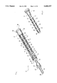
- FIG. 1 is a partial cut-away perspective view of the present invention shock-absorbing device for the body frames of bicycles and motorcycles.
- FIG. 2 is an exploded perspective view of the present invention shock-absorbing device for the body frames of bicycles and motorcycles.
- FIG. 3 is a perspective view showing the multi-function sleeves of the present invention used in conjunction with replaceable elastomers such that all the elastomers can be removed together in an interconnected series, while each individual elastomer can be replaced without disturbing or disconnecting other elastomers.
- FIG. 4 is a perspective view showing one embodiment of the present invention multi-function sleeve used in conjunction with replaceable elastomers for adjustable shock-absorbing device for the body frames of bicycles and motorcycles.
- FIG. 5 is a top plan view of the multi-function sleeve shown in FIG. 4.
- FIG. 6 is a bottom plan view of the multi-function sleeve shown in FIG. 4.
- FIG. 7 is a side elevation view of the multi-function sleeve shown in FIG. 4.
- FIG. 8 is a cross-sectional view taken along line 8--8 of FIG. 4.
- FIG. 9 is an enlarged partial cross-sectional view showing that the uncompressed elastomers are interconnected by the multi-function sleeves.
- FIG. 10 is an enlarged partial cross-sectional view showing that the compressed elastomers are regulated and restrained by the multi-function sleeves shown in FIG, 4 and prevented from twisting and snaking.
- FIG. 11 is a cross-sectional view of the present invention shock-absorbing device for the body frames of bicycles and motorcycles utilizing the multi-function sleeves shown in FIG. 4 in conjunction with the multiplicity of elastomers.
- FIG. 12 is a perspective view showing another embodiment of the present invention multi-function sleeve used in conjunction with replaceable elastomers for adjustable shock-absorbing device for the body frames of bicycles and motorcycles.
- FIG. 13 is a top plan view of the multi-function sleeve shown in FIG. 12.
- FIG. 14 is a bottom plan view of the multi-function sleeve shown in FIG. 12.
- FIG. 15 is a side elevation view of the multi-function sleeve shown in FIG. 12.
- FIG. 16 is a cross-sectional view taken along line 16--16 of FIG. 12.
- FIG. 17 is an enlarged partial cross-sectional view showing that the uncompressed elastomers are interconnected by the multi-function sleeves shown in FIG. 12.
- FIG. 18 is an enlarged partial cross-sectional view showing that the compressed elastomers are regulated and restrained by the multi-function sleeves and prevented from twisting and snaking, and the drum shaped compressed elastomers are well accommodated by the beveled surfaces of the multi-function sleeves shown in FIG. 12.
- FIG. 19 is a cross-sectional view of the present invention shock-absorbing device for the body frames of bicycles and motorcycles utilizing the multi-function sleeves shown in FIG. 12 in conjunction with the multiplicity of elastomers.
- FIG. 20 is a perspective view showing still another embodiment of the present invention multi-function sleeve used in conjunction with replaceable elastomers for adjustable shock-absorbing device for the body frames of bicycles and motorcycles.
- FIG. 21 is a top plan view of the multi-function sleeve shown in FIG. 20.
- FIG. 22 is a bottom plan view of the multi-function sleeve shown in FIG. 20.
- FIG. 23 is a side elevation view of the multi-function sleeve shown in FIG. 20.
- FIG. 24 is a cross-sectional view taken along line 24--24 of FIG. 20.
- FIG. 25 s an enlarged partial cross-sectional view showing that the uncompressed elastomers are interconnected by the multi-function sleeves shown in FIG. 20.
- FIG. 26 is an enlarged partial cross-sectional view showing that the compressed elastomers are regulated and restrained by the multi-function sleeves and prevented from twisting and snaking, and the drum shaped compressed elastomers are further accommodated by the bowl-shaped surfaces of the multi-function sleeves shown in FIG. 20.
- FIG. 27 is a cross-sectional view of the present invention shock-absorbing device for the body frames of bicycles and motorcycles utilizing both the multi-function sleeve shown in FIG. 4 and the multi-function sleeve shown in FIG. 12 with identical or different sized elastomers.
- FIG. 28 is a cross-sectional view of the present invention shock-absorbing device for the body frames of bicycles and motorcycles, showing another example of the possible configurations of the elastomer and multi-function sleeve assembly.
- the present invention shock-absorbing apparatus for use in the body frames of light-weight pedal-powered or motor-powered land or water surface vehicles and sports and exercising equipment.
- These light-weight pedal-powered or motor-powered land or water surface vehicles and sports and exercising equipment include, but are not limited to, bicycles, mountain bikes, dirt bikes, off-road bikes, all terrain bikes, exercise bikes, motor-bikes, motorcycles, mopeds, scooters, snow-scooters, snow-mobiles, jet-skis and the like.
- the shock-absorbing apparatus 10 comprises a telescoping assembly 12.
- the telescoping assembly 12 includes a generally cylindrical shaped elongated hollow tube 20 and a generally cylindrical shaped elongated compression rod 30.
- the hollow cylindrical tube 20 has a proximal end portion 22 which terminates at a proximal end 24, and a distal end portion 26 which terminates at a distal end 28.
- the compression rod also has a proximal end portion 32 which terminates at a proximal end 34, and a distal end portion 36 which terminates at a distal end 38.
- the hollow tube 20 and the compression rod 30 are slidably engaged coaxially, where the proximal end portion 32 of the compression rod 30 is extending inside the tube 20 from the proximal end 24 of the tube 20.
- the proximal end 22 of the tube 20 has a bushing 25, and the proximal end 32 of the compression rod has a widened compression flange 31.
- the shock-absorbing apparatus 10 also comprises a compression elastomer assembly 14.
- the compression elastomer assembly 14 includes a multiplicity of generally cylindrical shaped resilient and deformable compression elastomers 40 and a multiplicity of generally cylindrical shaped rigid hollow multi-function sleeves 50. Each multi-function sleeve has two opposite ends and is positioned between two adjacent compression elastomers.
- the compression elastomers 40 are made of rubber or synthetic rubber material or like resilient and deformable materials.
- the number, hardness or compressibility, as well as the length of the elastomers may vary according to the desire of the individual user of the vehicle or equipment on which the present invention shock-absorbing apparatus 10 is utilized.
- Two of the six (6) elastomers 41, 42, 43, 44, 45 and 46 may be hard elastomers, two of them may be medium elastomers, and two of them may be soft elastomers. Accordingly, there are five (5) multi-function sleeves 51, 52, 53, 54 and 55 placed between the six (6) elastomers 41, 42, 43, 44, 45 and 46.
- the multi-function sleeve 60 has a cylindrical circumferential sidewall 62.
- the cylindrical circumferential sidewall 62 has an exterior surface 61 and an interior surface 63.
- the interior surface 63 of the sidewall 62 defines a hollow cylindrical chamber 64 which is accessible from both of the two opposite ends of the multi-function sleeve 60.
- the multi-function sleeve 60 further has an integral internal partition 66 located inside the hollow chamber 64.
- the multi-function sleeve 60 has a generally "H" shaped cross-sectional configuration.
- the rigid multi-function sleeves 60 serve to interconnect the resilient elastomers 40 in a stacked series.
- the rigid multi-function sleeves 60 also serve to regulate the elastomers 40 to prevent them from twisting or snaking when they are compressed.
- two adjacent compression elastomers 40 are interconnected by one multi-function sleeve 60 at its two opposite ends respectively through press-fit engagement, where the internal diameter of the hollow chamber 64 of the sleeve 60 is slightly less than the external diameter of the two adjacent elastomers 40.
- the adjacent elastomers 40 are engaged through press-fit with the interior surface 63 of the sidewall 62 of the sleeve 60, and abutted by the internal partition 66 which prevents relative movement along the coaxial direction between the sleeve 60 and the adjacent elastomers 40.
- each elastomer 40 deforms into a generally drum shaped configuration which fills the gap between the sidewalls 62 of the rigid sleeves 60. This feature prevents any hard contact between the sidewalls 62 of adjacent rigid sleeves 60.
- the series of resilient elastomers 40 are maintained in a coaxial stack along the axial direction of the tube 20 by the multi-function sleeves 60 Without the multi-function sleeves 60, it will be hard to maintain the coaxial alignment of the elastomers 40, and when the elastomers are compressed, bending, twisting, bending and snaking are very likely to occur.
- the multi-function sleeve 70 also has a cylindrical circumferential sidewall 72.
- the cylindrical circumferential sidewall 72 again has an exterior surface 71 and an interior surface 73, where the interior surface 73 of the sidewall 72 defines a hollow chamber 74 which is accessible from both the two opposite ends of the multi-function sleeve 70.
- the multi-function sleeve 70 now has an integral internal annular shelf 76 located inside the hollow chamber 74. This feature of having an annular shelf, rather than an internal partition, reduces the weight and material cost of the sleeve 70.
- the multi-function sleeve 70 has a beveled surface 78 at each of its two opposite ends.
- the beveled surfaces 78 at both ends of the multi-function sleeve 70 converge into the hollow chamber 74 of the sleeve 70. This feature serves a function which will be discussed later.
- the multi-function sleeve 70 has an external annular groove or channel 79.
- the annular groove or channel 79 is recessed from the exterior surface 71 of the sidewall 72 of the multi-function sleeve 70. It serves the function of facilitating handling of the sleeve 70. It also reduces the weight and material cost of the multi-function sleeve 70. Therefore, in general, the multi-function sleeve 70 has a generally hourglass shaped cross-sectional configuration.
- the rigid multi-function sleeves 70 again serve to interconnect the resilient elastomers 40 in a stacked series.
- the rigid multi-function sleeves 70 also serve to regulate the elastomers 40 to prevent them from twisting or snaking when they are compressed.
- both ends of the multi-function sleeve 70 have beveled surfaces 78 which converge into the hollow chamber 74 of the sleeve 70, the interior surface 73 of the sidewall 72 of the sleeve still has a straight section 75 at each side of the internal shelf 76, which straight sections 75 are aligned with the axial direction of the sidewall 72.
- This feature ensures that the respective end portions of adjacent elastomers will always have a press-fit engagement with the sleeve 70 through the non-beveled straight sections 75.
- the beveled surface 78 at each of the ends of the multi-function sleeve 70 is designed to better accommodate the shape of the elastomers 40 when they are compressed.
- the deformable elastomers 40 When the deformable elastomers 40 are compressed, they deform into a generally drum shaped configuration.
- the beveled surface 78 at each of the ends of the multi-function sleeve 70 provides a better fitting between the deformed elastomers 40 and the sidewall 72 of the sleeve 70.
- the generally drum shaped configuration of the elastomer 40 fills the gap between the sidewalls 72 of adjacent sleeves 70 and prevents any hard contact therebetween.
- the series of resilient elastomers 40 are again maintained in a coaxial stack along the axial direction of the tube 20 by the multi-function sleeves 70.
- the use of multi-function sleeves 70 eliminates any bending, twisting, bending and snaking of the resilient elastomers when they are compressed.
- the multi-function sleeve 80 again has a cylindrical circumferential sidewall 82.
- the cylindrical circumferential sidewall 82 has an exterior surface 81 and an interior surface 83, where the interior surface 83 of the sidewall 82 defines a hollow chamber 84 which is accessible from both the two opposite ends of the multi-function sleeve 80.
- the multi-function sleeve 80 also has an integral internal annular shelf 86 located inside the hollow chamber 84.
- the multi-function sleeve 80 has a circular bowl-shaped surface 88 at each of its two opposite ends.
- the bowl-shaped surfaces 88 at both ends of the multi-function sleeve 80 again converge into the hollow chamber 84 of the sleeve 80. These bowl-shaped surfaces serve a function which will be discussed later.
- the rigid multi-function sleeves 80 again serve to interconnect the resilient elastomers 49 in a stacked series.
- the rigid multi-function sleeves 80 also serve to regulate the elastomers 49 to prevent them from twisting or snaking when they are compressed.
- the elastomers 49 shown in FIGS. 25 and 26 have an optional bore which serves the purpose of facilitating the inward expansion as the elastomers 49 being compressed.
- both ends of the multi-function sleeve 80 have circular bowl-shaped surfaces 88 which converge into the hollow chamber 84 of the sleeve 80, the interior surface 83 of the sidewall 82 of the sleeve still has a straight section 85 at each side of the internal shelf 86, which straight sections 85 are aligned with the axial direction of the sidewall 82.
- This feature ensures that the respective end portions of adjacent elastomers will always have a press-fit engagement with the sleeve 80 through the non-beveled straight sections 85.
- the bowl-shaped surface 88 at each of the ends of the multi-function sleeve 80 is designed to better accommodate the shape of the elastomers 49 when they are compressed.
- the deformable elastomers 49 When the deformable elastomers 49 are compressed, they deform into a generally drum shaped configuration.
- the bowl-shaped surface 88 at each of the ends of the multi-function sleeve 80 provides an enlarged room for the deformed elastomers 49.
- the generally drum shaped configuration of the elastomer 49 fills the gap between the sidewalls 82 of adjacent sleeves 80 and prevents any hard contact therebetween.
- the internal bores of the elastomers 49 increase the compressibility of the elastomers 49 because they allow the elastomers 49 to expand inwardly.
- FIGS. 27 and 28 there are shown that in other embodiments of the present invention shock-absorbing apparatus 10, different types of the multi-function sleeves can be used together with different types of compression elastomers. This feature provides greater flexibility to the individual user of the light-weight pedal-powered or motor-powered land or water surface vehicles and sports and exercising equipment which utilize the present invention shock-absorbing apparatus 10.
- the upper three smaller elastomers 40 are retained, but the lower three smaller elastomers are replaced by an elongated elastomer 90.
- Two generally "H" shaped multi-function sleeves 60 are used between the smaller elastomers 40, and a generally hourglass shaped multi-function sleeve 70 is used between the last smaller elastomer 40 and the elongated elastomer 90.
- the elongated elastomer 90 has a different deformation characteristic when compressed, and therefore provides a different shock-absorbing effect as compared to the smaller elastomers 40.
- One or more rigid annular bands 92 may be placed on the elongated elastomer 90 to prevent it from twisting and snaking.
- the width, number and location of the rigid bands further provide means for fine-tuning the compressibility of the elongated elastomer 90.
- all smaller elastomers are replaced by two elongated elastomers 90.
- a generally hourglass shaped multi-function sleeve 70 is used between the two elongated elastomers 90.
- Several rigid annular bands 92 may also be used together with the elongated elastomers 90 to prevent them from twisting and snaking.
- the present invention shock-absorbing apparatus may further comprise an end cap assembly 16.
- the end cap assembly 16 is removably threaded to the distal end 28 of the elongated tube 20. It includes an adaptor 18 which has an end socket 19 for press-fit engagement with elastomer 41, which is the first one of the multiplicity of elastomers 40 most close to the distal end 28 of the tube 20.
- elastomer 41 which is the first one of the multiplicity of elastomers 40 most close to the distal end 28 of the tube 20.
- the entire compression elastomer assembly 14, including all of the resilient elastomers and rigid sleeves, can be removed together with the end cap assembly from the tube 20.
- This feature makes it possible to remove the compression elastomer assembly from the tube 20 as one interconnected series.
- the elastomers are disconnected. Therefore, when the elastomers need to be removed, the tube has to be turned upside-down to dump the elastomers out. This means turning the whole vehicle or equipment upside-down if the tube is, for example, part of the front fork of the vehicle and the end cap is removable from the top end of the tube.
- the present invention shock-absorbing apparatus 10 has overcome this problem because all the elastomers 40 are interconnected by the multi-function sleeves 50.
- elastomers 40 in case one of the elastomers 40 needs to be replaced, it can be individually detached from the interconnected series of the elastomers and replaced without disturbing all the other interconnected elastomers.
- elastomer 42 if elastomer 42 needs to be replaced, it can be simply detached from the adjacent sleeves 51 and 52 without disturbing any one of the other interconnected elastomers 41, 43, 44, 45 and 46.
- the compression elastomer assembly 14 of the present invention shock-absorbing apparatus is positioned between end cap assembly 16 and the compression flange 31 of the compression rod 30.
- the compression flange 31 of the compression rod 30 contacts the last one of the multiplicity of elastomers, which is elastomer 46, the one most close to the proximal end 34 of the compression rod 30.
- the present invention shock-absorbing apparatus may also comprise an optional rebound damping assembly.
- the rebound damping assembly may include a rebound flange 33 located at the proximal end portion 32 of the elongated compression rod 30 inside the tube 20, and one or more rebound elastomers 35 placed on the compression rod 30 and positioned inside the tube 20 and between the rebound flange 33 of the compression rod 30 and the proximal end 22 of the tube 20.
- the rebound elastomers will provide a damping effect when rebound occurs upon the telescoping assembly 12.
- the present invention shock-absorbing apparatus may further comprise an optional bottom-out prevention assembly.
- the bottom-out prevention assembly may include a detachable clip 37 attached to the distal end portion 36 of the elongated compression rod 30, and one or more bottom-out elastomers 39 placed on the compression rod 30 and positioned outside of the tube 20 and between the proximal end 22 of the tube 20 and the detachable clip 37.
- the bottom-out elastomer 39 will prevent the telescoping assembly 12 from bottoming-out.
- the present invention shock-absorbing apparatus is designed to be used in the body frames of light-weight pedal-powered or motor-powered land or water surface vehicles and sports and exercising equipment, such as bicycles, mountain bikes, dirt bikes, off-road bikes, all terrain bikes, exercise bikes, motor-bikes, motorcycles, mopeds, scooters, snow-scooters, snow-mobiles, jet-skis and the like.
- the present invention shock-absorbing apparatus can be utilized in the front or rear wheel forks, or other suitable parts of the body frame, such as seat posts, of the above referenced vehicles or equipment.
- tile compression elastomer assembly shown in the examples of the present invention is placed in the telescoping assembly which includes a tube and a compression rod
- the compression elastomer assembly of the present invention shock-absorbing apparatus can be used with other types of telescoping assemblies, such as the type of telescoping assemblies which includes an outer tube and an inner tube.
- the present invention shock-absorbing apparatus has many advantageous features. It provides a new design and construction of a shock-absorbing suspension system utilizing a multiplicity of generally cylindrical shaped compressible elastomers, where the configuration of the elastomers assembly can be quickly and easily modified to adjust the compressibility of the shock-absorbing suspension system.
- each multi-function sleeve is positioned between two adjacent elastomers to interconnect the two adjacent elastomers, so that all the elastomers can be removed together in an interconnected series, while each individual elastomer can be replaced without disturbing or disconnecting other elastomers.
- the rigid multi-function sleeves further function as regulators and restrainers to the stacked resilient elastomers to prevent the stack of elastomers from twisting and snaking when they are compressed.
- each multi-function sleeve placed between two adjacent elastomers is interconnecting the two elastomers by press-fit engagement based upon the resiliency of the rubber elastomers, so that the press-fit can be tight enough to withhold the weight of the interconnected series of the elastomers and sleeves, but still allows removal of any one of the elastomers from the multi-function sleeve.
- This provides the desired interconnection between the two elastomers while still providing the flexibility of replacing any one of the elastomers individually.
- each multi-function sleeve placed between two adjacent elastomers has an integral internal structure located inside its hollow cylindrical chamber, so that the internal partition will prevent any relative sliding movement among the multi-function sleeve and the two adjacent elastomers.
- the internal structure can further be configured as a circular internal shelf, so that the weight and material cost of the multi-function sleeve are reduced.
- the exterior cylindrical sidewall of each multi-function sleeve may also have an annular groove, so that the weight and material cost of the multi-function sleeve are further reduced and the annular groove can better facilitate the handling of the multi-function sleeves.
- each multi-function sleeve placed between two adjacent elastomers has a circular beveled or bowl-shaped surface at each of its two opposite ends converging into the hollow cylindrical chamber of the multi-function sleeve, which can better accommodate the drum shaped elastomers when they are compressed.
- the present invention is a shock-absorbing apparatus for use in the body frames of light-weight pedal-powered or motor-powered land or water surface vehicles and sports and exercising equipment including bicycles, mountain bikes, dirt bikes, off-road bikes, all terrain bikes, exercise bikes, motor-bikes, motorcycles, mopeds, scooters, snow-scooters, snow-mobiles, jet-skis and the like, the shock-absorbing apparatus comprising: (a) a telescoping assembly including an elongated hollow cylindrical tube and an elongated cylindrical compression rod, the tube and the compression rod each having a proximal end portion terminated at a proximal end and a distal end portion terminated at a distal end, the tube and compression rod further slidably engaged coaxially with the proximal end portion of the compression rod extending inside the tube; (b) a compression elastomer assembly including a multiplicity of cylindrical shaped resilient and deformable compression elastomers and a multiplicity of hollow cylindrical shaped rigid multi-
- the present invention is a shock-absorbing apparatus for use in the body frames of light-weight pedal-powered or motor-powered land or water surface vehicles and sports and exercising equipment including bicycles, mountain bikes, dirt bikes, off-road bikes, all terrain bikes, exercise bikes, motor-bikes, motorcycles, mopeds, scooters, snow-scooters, snow-mobiles, jet-skis and the like, the shock-absorbing apparatus comprising: (a) a telescoping assembly including a generally hollow cylindrical shaped elongated tube and a generally cylindrical shaped elongated compression rod, the tube and the compression rod each having a proximal end and a distal end, the tube and compression rod further slidably engaged coaxially with the proximal end of the compression rod extending inside the tube; (b) a compression elastomer assembly including a multiplicity of generally cylindrical shaped resilient and deformable compression elastomers and a multiplicity of generally hollow cylindrical shaped rigid multi-function sleeves, the compression elastomers placed co
- the present invention is a shock-absorbing apparatus for use in the body frames of light-weight pedal-powered or motor-powered land or water surface vehicles and sports and exercising equipment including bicycles, mountain bikes, dirt bikes, off-road bikes, all terrain bikes, exercise bikes, motor-bikes, motorcycles, mopeds, scooters, snow-scooters, snow-mobiles, jet-skis and the like, the shock-absorbing apparatus comprising: (a) a telescoping assembly including an elongated hollow tube and an elongated compression rod coaxially and slidably engaged; (b) a compression elastomer assembly including at least two resilient and deformable compression elastomers placed between the tube and compression rod and at least one rigid multi-function sleeve positioned between the at least two compression elastomers; (c) the multi-function sleeve having a circumferential sidewall with an exterior surface and an interior surface, the interior surface defining a hollow chamber which is accessible from two opposite ends of the multi-function
- the present invention is a shock-absorbing apparatus for use in the body frames of light-weight pedal-powered or motor-powered land or water surface vehicles and sports and exercising equipment including bicycles, mountain bikes, dirt bikes, off-road bikes, all terrain bikes, exercise bikes, motor-bikes, motorcycles, mopeds, scooters, snow-scooters, snow-mobiles, jet-skis and the like, the shock-absorbing apparatus comprising: (a) a telescoping assembly including an elongated hollow cylindrical tube and an elongated cylindrical compression rod, the tube and the compression rod each having a proximal end portion terminated at a proximal end and a distal end portion terminated at a distal end, the tube and compression rod further slidably engaged coaxially with the proximal end portion of the compression rod extending inside the tube; (b) a compression elastomer assembly including a multiplicity of cylindrical shaped resilient and deformable compression elastomers and a multiplicity of hollow cylindrical shaped rigid multi
- the present invention is a shock-absorbing apparatus for use in the body frames of light-weight pedal-powered or motor-powered land or water surface vehicles and sports and exercising equipment including bicycles, mountain bikes, dirt bikes, off-road bikes, all terrain bikes, exercise bikes, motor-bikes, motorcycles, mopeds, scooters, snow-scooters, snow-mobiles, jet-skis and the like, the shock-absorbing apparatus comprising: (a) a telescoping assembly including a generally hollow cylindrical shaped elongated tube and a generally cylindrical shaped elongated compression rod, the tube and the compression rod each having a proximal end and a distal end, the tube and compression rod further slidably engaged coaxially with the proximal end of the compression rod extending inside the tube; (b) a compression elastomer assembly including a multiplicity of generally cylindrical shaped resilient and deformable compression elastomers and a multiplicity of generally hollow cylindrical shaped rigid multi-function sleeves, the compression elastomers placed
- the present invention is a shock-absorbing apparatus for use in the body frames of light-weight pedal-powered or motor-powered land or water surface vehicles and sports and exercising equipment including bicycles, mountain bikes, dirt bikes, off-road bikes, all terrain bikes, exercise bikes, motor-bikes, motorcycles, mopeds, scooters, snow-scooters, snow-mobiles, jet-skis and the like, the shock-absorbing apparatus comprising: (a) a telescoping assembly including an elongated hollow tube and an elongated compression rod coaxially and slidably engaged; (b) a compression elastomer assembly including at least two resilient and deformable compression elastomers placed between the tube and compression rod and at least one rigid multi-function sleeve positioned between the at least two compression elastomers; (c) the multi-function sleeve having a circumferential sidewall with an exterior surface and an interior surface, the interior surface defining a hollow chamber which is accessible from two opposite ends of the multi-function
- the present invention is a shock-absorbing apparatus for use in the body frames of light-weight pedal-powered or motor-powered land or water surface vehicles and sports and exercising equipment including bicycles, mountain bikes, dirt bikes, off-road bikes, all terrain bikes, exercise bikes, motor-bikes, motorcycles, mopeds, scooters, snow-scooters, snow-mobiles, jet-skis and the like, the shock-absorbing apparatus comprising: (a) a telescoping assembly including an elongated hollow cylindrical tube and an elongated cylindrical compression rod, the tube and the compression rod each having a proximal end portion terminated at a proximal end and a distal end portion terminated at a distal end, the tube and compression rod further slidably engaged coaxially with the proximal end portion of the compression rod extending inside the tube; (b) a compression elastomer assembly including a multiplicity of cylindrical shaped resilient and deformable compression elastomers and a multiplicity of hollow cylindrical shaped rigid multi-function sleeves
- the present invention is a shock-absorbing apparatus for use in the body frames of light-weight pedal-powered or motor-powered land or water surface vehicles and sports and exercising equipment including bicycles, mountain bikes, dirt bikes, off-road bikes, all terrain bikes, exercise bikes, motor-bikes, motorcycles, mopeds, scooters, snow-scooters, snow-mobiles, jet-skis and the like, the shock-absorbing apparatus comprising: (a) a telescoping assembly including a generally hollow cylindrical shaped elongated tube and a generally cylindrical shaped elongated compression rod, the tube and the compression rod each having a proximal end and a distal end, the tube and compression rod further slidably engaged coaxially with the proximal end of the compression rod extending inside the tube; (b) a compression elastomer assembly including a multiplicity of generally cylindrical shaped resilient and deformable compression elastomers and a multiplicity of generally hollow cylindrical shaped rigid multi-function sleeves, the compression elastomers placed coaxial
- the present invention is a shock-absorbing apparatus for use in the body frames of light-weight pedal-powered or motor-powered land or water surface vehicles and sports and exercising equipment including bicycles, mountain bikes, dirt bikes, off-road bikes, all terrain bikes, exercise bikes, motor-bikes, motorcycles, mopeds, scooters, snow-scooters, snow-mobiles, jet-skis and the like, the shock-absorbing apparatus comprising: (a) a telescoping assembly including an elongated hollow tube and an elongated compression rod coaxially and slidably engaged; (b) a compression elastomer assembly including at least three resilient and deformable compression elastomers placed between the tube and compression rod and at least two rigid multi-function sleeve positioned between the at least three compression elastomers; (c) the multi-function sleeves having a circumferential sidewall with an exterior surface and an interior surface, the interior surface defining a hollow chamber which is accessible from two opposite ends of the multi-function sleeve,
- the present invention is a shock-absorbing apparatus for use in the body frames of light-weight pedal-powered or motor-powered land or water surface vehicles and sports and exercising equipment including bicycles, mountain bikes, dirt bikes, off-road bikes, all terrain bikes, exercise bikes, motor-bikes, motorcycles, mopeds, scooters, snow-scooters, snow-mobiles, jet-skis and the like, the shock-absorbing apparatus comprising: (a) a telescoping assembly including two members which can move relatively with regard to each other; (b) a compression elastomer assembly including at least two resilient and deformable compression elastomers placed between the two members and at least one rigid multi-function sleeve positioned between the at least two compression elastomers; (c) the multi-function sleeve having a circumferential sidewall with an exterior surface and an interior surface, the interior surface defining a hollow chamber which is accessible from two opposite ends of the multi-function sleeve, the internal diameter of the hollow chamber being slightly less
Landscapes
- Engineering & Computer Science (AREA)
- General Engineering & Computer Science (AREA)
- Mechanical Engineering (AREA)
- Health & Medical Sciences (AREA)
- Child & Adolescent Psychology (AREA)
- Architecture (AREA)
- Vibration Dampers (AREA)
Abstract
Description
Claims (13)
Priority Applications (1)
| Application Number | Priority Date | Filing Date | Title |
|---|---|---|---|
| US08/235,539 US5460357A (en) | 1994-04-29 | 1994-04-29 | Multi-function sleeves used in conjunction with replaceable elastomers for adjustable shock-absorbing suspension systems of bicycles and motorcycles |
Applications Claiming Priority (1)
| Application Number | Priority Date | Filing Date | Title |
|---|---|---|---|
| US08/235,539 US5460357A (en) | 1994-04-29 | 1994-04-29 | Multi-function sleeves used in conjunction with replaceable elastomers for adjustable shock-absorbing suspension systems of bicycles and motorcycles |
Publications (1)
| Publication Number | Publication Date |
|---|---|
| US5460357A true US5460357A (en) | 1995-10-24 |
Family
ID=22885910
Family Applications (1)
| Application Number | Title | Priority Date | Filing Date |
|---|---|---|---|
| US08/235,539 Expired - Fee Related US5460357A (en) | 1994-04-29 | 1994-04-29 | Multi-function sleeves used in conjunction with replaceable elastomers for adjustable shock-absorbing suspension systems of bicycles and motorcycles |
Country Status (1)
| Country | Link |
|---|---|
| US (1) | US5460357A (en) |
Cited By (28)
| Publication number | Priority date | Publication date | Assignee | Title |
|---|---|---|---|---|
| US5529327A (en) * | 1995-02-08 | 1996-06-25 | Aprebic Industry Co., Ltd. | Shock absorbing device for a bicycle |
| US5597169A (en) * | 1993-09-07 | 1997-01-28 | Manitou Maountain Bikes, Inc. | Suspension fork for bicycles |
| US5720474A (en) * | 1995-04-17 | 1998-02-24 | Sugiyama; Kazuo | Shock absorbing mechanism of displacement for stick, leg, etc. |
| US5848675A (en) * | 1996-10-03 | 1998-12-15 | Answer Products, Inc. | Damping apparatus for bicycle forks |
| US5957441A (en) * | 1997-09-05 | 1999-09-28 | Miner Enterprises, Inc. | Hourglass-shaped elastomeric compression spring |
| US5961556A (en) * | 1996-12-31 | 1999-10-05 | Lord Corporation | Prosthetic suspension unit having elastomeric energy storage units |
| US6202995B1 (en) * | 1999-06-29 | 2001-03-20 | Perfection Mighty Industrial Co., Ltd. | Shock absorbing elastic block and shock absorber using the same |
| US6220585B1 (en) * | 1998-10-29 | 2001-04-24 | Timbren Industries Incorporated | Multi-stage compression spring |
| US6250617B1 (en) | 1999-01-19 | 2001-06-26 | Miner Enterprises, Inc. | Shock attenuating apparatus |
| US6296238B1 (en) * | 1996-11-08 | 2001-10-02 | Birger Lund-Andersen | Device for the damping of vibrations between objects |
| US6328294B1 (en) * | 1999-11-02 | 2001-12-11 | Ck Witco Corporation | Elastomeric spring system |
| US6443437B1 (en) * | 2000-05-17 | 2002-09-03 | Lord Corporation | Suspension strut with damping |
| US6505719B2 (en) | 1998-05-18 | 2003-01-14 | Answer Products, Inc. | Damping apparatus for bicycle forks |
| US6619611B2 (en) * | 2001-07-02 | 2003-09-16 | Newport Corporation | Pneumatic vibration isolator utilizing an elastomeric element for isolation and attenuation of horizontal vibration |
| US20040075204A1 (en) * | 2001-02-07 | 2004-04-22 | Josef Heidemann | Spring element |
| US6848701B2 (en) * | 2002-07-12 | 2005-02-01 | Specialized Bicycle Components, Inc. | Bicycle seat post assembly |
| US20070035073A1 (en) * | 2005-08-10 | 2007-02-15 | Kinmartin Jeffrey C | Isolation for electric motor |
| US20090032243A1 (en) * | 2007-08-03 | 2009-02-05 | Victor Bruce M | Polymer Shock Absorber for Use with Well Head Lubricator Assembly |
| US20100000752A1 (en) * | 2008-06-11 | 2010-01-07 | Black & Decker Inc. | Resilient Stop Assembly For Impact Tool |
| US20110248469A1 (en) * | 2010-04-07 | 2011-10-13 | Specialized Bicycle Components, Inc. | Bicycle damping system |
| CN102431205A (en) * | 2011-12-13 | 2012-05-02 | 北京隆轩橡塑有限公司 | Precompression device for polymer compression spring |
| US8360140B2 (en) | 2010-03-16 | 2013-01-29 | Miner Elastomer Products Corporation | Well head lubricator assembly |
| US8540267B1 (en) | 2012-03-23 | 2013-09-24 | Specialized Bicycle Components, Inc. | Bicycle damping system |
| US8888115B2 (en) | 2010-04-07 | 2014-11-18 | Specialized Bicycle Components, Inc. | Bicycle seat tube |
| CN107672726A (en) * | 2017-10-25 | 2018-02-09 | 深圳市怡康乐科技有限公司 | It is a kind of can arbitrarily convenient disassembly carry and assembling handlebar group structure |
| US9957008B1 (en) * | 2017-03-06 | 2018-05-01 | Taiwan Hodaka Industrial Co., Ltd. | Bicycle seatpost structure |
| US20180363721A1 (en) * | 2016-02-09 | 2018-12-20 | Uhde High Pressure Technologies Gmbh | Spring device and securing device for securing a machine element, and use thereof |
| US20190316646A1 (en) * | 2016-12-13 | 2019-10-17 | Cdm Nv | Layered support |
Citations (13)
| Publication number | Priority date | Publication date | Assignee | Title |
|---|---|---|---|---|
| DE173984C (en) * | ||||
| US28619A (en) * | 1860-06-05 | Richard vose | ||
| US2683034A (en) * | 1948-12-09 | 1954-07-06 | Dunlop Rubber Co | Rubber compression spring |
| US2683044A (en) * | 1948-07-08 | 1954-07-06 | Dunlop Rubber Co | Shock-absorbing device |
| US2708112A (en) * | 1951-10-16 | 1955-05-10 | Dunlop Rubber Co | Shock absorbers |
| USRE24654E (en) * | 1952-03-15 | 1959-06-02 | Cupped elastic plunger type snubber | |
| US3606295A (en) * | 1968-11-12 | 1971-09-20 | Unilan Ag | Shock absorber |
| SU968528A1 (en) * | 1981-01-09 | 1982-10-23 | Проектный Научно-Исследовательский Институт "Харьковский Промстройниипроект" | Vibration insulation support assembly |
| US4561641A (en) * | 1978-09-18 | 1985-12-31 | Clark Equipment Company | Off-highway vehicle ride strut and method |
| US4905799A (en) * | 1988-04-04 | 1990-03-06 | Atsugi Motor Parts Company, Limited | Shock absorber |
| US5193832A (en) * | 1991-09-19 | 1993-03-16 | Wilson Stephen R | Suspension for bicyles |
| US5193833A (en) * | 1990-08-24 | 1993-03-16 | Robert Reisinger | Bicycle front suspension, steering & braking system |
| US5269549A (en) * | 1991-09-19 | 1993-12-14 | Wilson Stephen R | Suspension for bicycles |
-
1994
- 1994-04-29 US US08/235,539 patent/US5460357A/en not_active Expired - Fee Related
Patent Citations (13)
| Publication number | Priority date | Publication date | Assignee | Title |
|---|---|---|---|---|
| DE173984C (en) * | ||||
| US28619A (en) * | 1860-06-05 | Richard vose | ||
| US2683044A (en) * | 1948-07-08 | 1954-07-06 | Dunlop Rubber Co | Shock-absorbing device |
| US2683034A (en) * | 1948-12-09 | 1954-07-06 | Dunlop Rubber Co | Rubber compression spring |
| US2708112A (en) * | 1951-10-16 | 1955-05-10 | Dunlop Rubber Co | Shock absorbers |
| USRE24654E (en) * | 1952-03-15 | 1959-06-02 | Cupped elastic plunger type snubber | |
| US3606295A (en) * | 1968-11-12 | 1971-09-20 | Unilan Ag | Shock absorber |
| US4561641A (en) * | 1978-09-18 | 1985-12-31 | Clark Equipment Company | Off-highway vehicle ride strut and method |
| SU968528A1 (en) * | 1981-01-09 | 1982-10-23 | Проектный Научно-Исследовательский Институт "Харьковский Промстройниипроект" | Vibration insulation support assembly |
| US4905799A (en) * | 1988-04-04 | 1990-03-06 | Atsugi Motor Parts Company, Limited | Shock absorber |
| US5193833A (en) * | 1990-08-24 | 1993-03-16 | Robert Reisinger | Bicycle front suspension, steering & braking system |
| US5193832A (en) * | 1991-09-19 | 1993-03-16 | Wilson Stephen R | Suspension for bicyles |
| US5269549A (en) * | 1991-09-19 | 1993-12-14 | Wilson Stephen R | Suspension for bicycles |
Cited By (36)
| Publication number | Priority date | Publication date | Assignee | Title |
|---|---|---|---|---|
| US5597169A (en) * | 1993-09-07 | 1997-01-28 | Manitou Maountain Bikes, Inc. | Suspension fork for bicycles |
| US5529327A (en) * | 1995-02-08 | 1996-06-25 | Aprebic Industry Co., Ltd. | Shock absorbing device for a bicycle |
| US5720474A (en) * | 1995-04-17 | 1998-02-24 | Sugiyama; Kazuo | Shock absorbing mechanism of displacement for stick, leg, etc. |
| US5848675A (en) * | 1996-10-03 | 1998-12-15 | Answer Products, Inc. | Damping apparatus for bicycle forks |
| US6360858B2 (en) | 1996-10-03 | 2002-03-26 | Answer Products, Inc. | Damping apparatus for bicycle forks |
| US6296238B1 (en) * | 1996-11-08 | 2001-10-02 | Birger Lund-Andersen | Device for the damping of vibrations between objects |
| US5961556A (en) * | 1996-12-31 | 1999-10-05 | Lord Corporation | Prosthetic suspension unit having elastomeric energy storage units |
| US6102354A (en) * | 1996-12-31 | 2000-08-15 | Lord Corporation | Long stroke, linear energy management unit |
| US5957441A (en) * | 1997-09-05 | 1999-09-28 | Miner Enterprises, Inc. | Hourglass-shaped elastomeric compression spring |
| US6505719B2 (en) | 1998-05-18 | 2003-01-14 | Answer Products, Inc. | Damping apparatus for bicycle forks |
| US6220585B1 (en) * | 1998-10-29 | 2001-04-24 | Timbren Industries Incorporated | Multi-stage compression spring |
| US6250617B1 (en) | 1999-01-19 | 2001-06-26 | Miner Enterprises, Inc. | Shock attenuating apparatus |
| US6202995B1 (en) * | 1999-06-29 | 2001-03-20 | Perfection Mighty Industrial Co., Ltd. | Shock absorbing elastic block and shock absorber using the same |
| US6328294B1 (en) * | 1999-11-02 | 2001-12-11 | Ck Witco Corporation | Elastomeric spring system |
| US6443437B1 (en) * | 2000-05-17 | 2002-09-03 | Lord Corporation | Suspension strut with damping |
| US20040075204A1 (en) * | 2001-02-07 | 2004-04-22 | Josef Heidemann | Spring element |
| US6619611B2 (en) * | 2001-07-02 | 2003-09-16 | Newport Corporation | Pneumatic vibration isolator utilizing an elastomeric element for isolation and attenuation of horizontal vibration |
| US6848701B2 (en) * | 2002-07-12 | 2005-02-01 | Specialized Bicycle Components, Inc. | Bicycle seat post assembly |
| US20070035073A1 (en) * | 2005-08-10 | 2007-02-15 | Kinmartin Jeffrey C | Isolation for electric motor |
| US7669648B2 (en) * | 2007-08-03 | 2010-03-02 | Production Control Services, Inc. | Polymer shock absorber for use with well head lubricator assembly |
| US20090032243A1 (en) * | 2007-08-03 | 2009-02-05 | Victor Bruce M | Polymer Shock Absorber for Use with Well Head Lubricator Assembly |
| US20100000752A1 (en) * | 2008-06-11 | 2010-01-07 | Black & Decker Inc. | Resilient Stop Assembly For Impact Tool |
| US8104547B2 (en) * | 2008-06-11 | 2012-01-31 | Black & Decker Inc. | Resilient stop assembly for impact tool |
| US8360140B2 (en) | 2010-03-16 | 2013-01-29 | Miner Elastomer Products Corporation | Well head lubricator assembly |
| US8888115B2 (en) | 2010-04-07 | 2014-11-18 | Specialized Bicycle Components, Inc. | Bicycle seat tube |
| US20110248469A1 (en) * | 2010-04-07 | 2011-10-13 | Specialized Bicycle Components, Inc. | Bicycle damping system |
| US8454044B2 (en) * | 2010-04-07 | 2013-06-04 | Specialized Bicycle Components, Inc. | Bicycle damping system |
| US8678416B2 (en) | 2010-04-07 | 2014-03-25 | Specialized Bicycle Components, Inc. | Bicycle damping system |
| CN102431205A (en) * | 2011-12-13 | 2012-05-02 | 北京隆轩橡塑有限公司 | Precompression device for polymer compression spring |
| US8540267B1 (en) | 2012-03-23 | 2013-09-24 | Specialized Bicycle Components, Inc. | Bicycle damping system |
| US20180363721A1 (en) * | 2016-02-09 | 2018-12-20 | Uhde High Pressure Technologies Gmbh | Spring device and securing device for securing a machine element, and use thereof |
| US11092208B2 (en) * | 2016-02-09 | 2021-08-17 | Uhde High Pressure Technologies Gmbh | Spring device and securing device for securing a machine element, and use thereof |
| US20190316646A1 (en) * | 2016-12-13 | 2019-10-17 | Cdm Nv | Layered support |
| US11971078B2 (en) * | 2016-12-13 | 2024-04-30 | Cdm Stravitec Nv | Layered support |
| US9957008B1 (en) * | 2017-03-06 | 2018-05-01 | Taiwan Hodaka Industrial Co., Ltd. | Bicycle seatpost structure |
| CN107672726A (en) * | 2017-10-25 | 2018-02-09 | 深圳市怡康乐科技有限公司 | It is a kind of can arbitrarily convenient disassembly carry and assembling handlebar group structure |
Similar Documents
| Publication | Publication Date | Title |
|---|---|---|
| US5460357A (en) | Multi-function sleeves used in conjunction with replaceable elastomers for adjustable shock-absorbing suspension systems of bicycles and motorcycles | |
| US5509676A (en) | Shock absorber for a bicycle front fork | |
| US6318525B1 (en) | Shock absorber with improved damping | |
| US5445401A (en) | Suspension fork for bicycles | |
| US11787496B2 (en) | Suspension assembly and bicycle having a suspension assembly | |
| US5470090A (en) | Precision suspension fork for bicylces | |
| US5310203A (en) | Bicycle shock-absorbing apparatus | |
| JP3136741U (en) | Bicycle saddle assembly | |
| US5509675A (en) | Bicycle front suspension system | |
| US5820114A (en) | Shock absorber | |
| JPH09511819A (en) | Bicycle fork suspension | |
| JPH0624375A (en) | Post assembly for mounting bicycle cushioning seat | |
| FR2757107A1 (en) | VEHICLE WHEEL SUSPENSIONS USING A COMBINED SPRING WITH A SOFT ARMATURE INTENDED TO MODIFY ITS STIFFNESS CURVE | |
| US5775454A (en) | Motorcycle with front fender mounting system | |
| US5429344A (en) | Multi-function bands used in conjunction with an elongated elastomer for adjustable shock-absorbing suspension systems of bicycles and motorcycles | |
| US6202995B1 (en) | Shock absorbing elastic block and shock absorber using the same | |
| US6149175A (en) | Bicycle suspension | |
| US20040012232A1 (en) | Shock-absorbing bicycle seat mount system | |
| US20080036288A1 (en) | Wheel Shock Absorbing Apparatus | |
| US6406101B2 (en) | Shock absorbing bicycle wheel hub | |
| TWI886422B (en) | Shock absorption assembly | |
| USRE35401E (en) | Suspension for bicycles | |
| JP2006143188A (en) | Bicycle suspension assembly | |
| WO1998005548A1 (en) | Bicycle fork suspension with interchangeable spring stops | |
| US20050110237A1 (en) | Front fork unit with a shock absorber and a resistance-providing member for a bicycle |
Legal Events
| Date | Code | Title | Description |
|---|---|---|---|
| AS | Assignment |
Owner name: ANSWER PRODUCTS, INC., CALIFORNIA Free format text: ASSIGNMENT OF ASSIGNORS INTEREST;ASSIGNOR:STEWART, GERALD M.;REEL/FRAME:006982/0108 Effective date: 19940427 |
|
| FPAY | Fee payment |
Year of fee payment: 4 |
|
| AS | Assignment |
Owner name: BANK OF AMERICA, N.A. AS AGENT, ILLINOIS Free format text: SECURITY AGREEMENT;ASSIGNOR:ANSWER PRODUCTS, INC.;REEL/FRAME:012090/0408 Effective date: 20010215 |
|
| LAPS | Lapse for failure to pay maintenance fees | ||
| LAPS | Lapse for failure to pay maintenance fees |
Free format text: PATENT EXPIRED FOR FAILURE TO PAY MAINTENANCE FEES (ORIGINAL EVENT CODE: EXP.); ENTITY STATUS OF PATENT OWNER: LARGE ENTITY |
|
| STCH | Information on status: patent discontinuation |
Free format text: PATENT EXPIRED DUE TO NONPAYMENT OF MAINTENANCE FEES UNDER 37 CFR 1.362 |
|
| FP | Lapsed due to failure to pay maintenance fee |
Effective date: 20031024 |
|
| AS | Assignment |
Owner name: ANSWER PRODUCTS, INC., CALIFORNIA Free format text: RELEASE OF SECURITY INTEREST;ASSIGNOR:BANK OF AMERICA N.A., AS AGENT;REEL/FRAME:014468/0692 Effective date: 20040331 |