US5457765A - Apparatus for adjusting alignment of optical fibers - Google Patents
Apparatus for adjusting alignment of optical fibers Download PDFInfo
- Publication number
- US5457765A US5457765A US08/294,806 US29480694A US5457765A US 5457765 A US5457765 A US 5457765A US 29480694 A US29480694 A US 29480694A US 5457765 A US5457765 A US 5457765A
- Authority
- US
- United States
- Prior art keywords
- movable member
- groove
- fixed
- grooves
- movable
- Prior art date
- Legal status (The legal status is an assumption and is not a legal conclusion. Google has not performed a legal analysis and makes no representation as to the accuracy of the status listed.)
- Expired - Fee Related
Links
Images


Classifications
-
- G—PHYSICS
- G02—OPTICS
- G02B—OPTICAL ELEMENTS, SYSTEMS OR APPARATUS
- G02B6/00—Light guides; Structural details of arrangements comprising light guides and other optical elements, e.g. couplings
- G02B6/24—Coupling light guides
- G02B6/255—Splicing of light guides, e.g. by fusion or bonding
- G02B6/2555—Alignment or adjustment devices for aligning prior to splicing
-
- G—PHYSICS
- G02—OPTICS
- G02B—OPTICAL ELEMENTS, SYSTEMS OR APPARATUS
- G02B6/00—Light guides; Structural details of arrangements comprising light guides and other optical elements, e.g. couplings
- G02B6/24—Coupling light guides
- G02B6/255—Splicing of light guides, e.g. by fusion or bonding
- G02B6/2551—Splicing of light guides, e.g. by fusion or bonding using thermal methods, e.g. fusion welding by arc discharge, laser beam, plasma torch
-
- G—PHYSICS
- G02—OPTICS
- G02B—OPTICAL ELEMENTS, SYSTEMS OR APPARATUS
- G02B6/00—Light guides; Structural details of arrangements comprising light guides and other optical elements, e.g. couplings
- G02B6/24—Coupling light guides
- G02B6/42—Coupling light guides with opto-electronic elements
- G02B6/4201—Packages, e.g. shape, construction, internal or external details
- G02B6/4219—Mechanical fixtures for holding or positioning the elements relative to each other in the couplings; Alignment methods for the elements, e.g. measuring or observing methods especially used therefor
- G02B6/422—Active alignment, i.e. moving the elements in response to the detected degree of coupling or position of the elements
- G02B6/4226—Positioning means for moving the elements into alignment, e.g. alignment screws, deformation of the mount
Definitions
- the present invention relates to an apparatus for adjusting an alignment of optical fibers constituting optical fiber ribbons, which is useful in the fusion splicing of the optical fibers for example.
- the alignment of the core axes of the optical fibers to be fusion spliced has been achieved by mounting the optical fibers to be fusion spliced on V-grooves for fixedly mounting the optical fibers which are precisely machined along a straight line so as to be able to align the cladding axes of the optical fibers to be fusion spliced, and then by utilizing the self-alignment effect of the optical fibers due to the surface tension exerted on the optical fibers during the discharge heating process.
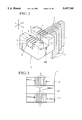
- each optical fiber 101 there is provided a pair of movable members 102A and 102B having approximately 45° inclined end faces to form a V-groove for mounting each optical fiber 101, each of which is supported by a stationary fixed guide member 100 to be minutely movable up or down, and moved up or down by a stack type piezoelectric element.
- the position of the optical fiber 101 is adjusted in a desired direction by the appropriate combination of the up and down minute movements of these movable members 102A and 102B so as to adjust the alignment of the optical fibers.
- an apparatus for adjusting an alignment of optical fibers comprising: a base frame having a plurality of pairs of V-grooves for mounting the optical fibers at mutually facing sides of the base frame, each V-groove being defined by a fixed member and a movable member, each movable member being movable within a guide groove defined between each adjacent fixed members, and one of each pair of V-grooves on one of said mutually facing sides has the fixed member and the movable member facing against the movable member and the fixed member, respectively, of another one of said each pair of V-grooves on another one of said mutually facing sides; and a plurality of piezoelectric elements, each of which is connected with each movable member of each V-groove, for causing said each movable member to move within the guide groove such that a displacement of said each movable member makes an adjustment of a position of an optical fiber mounted on said each V-groove.
- an apparatus for adjusting an alignment of optical fibers comprising: a base frame having at least one pair of V-grooves for mounting the optical fibers at mutually facing sides of the base frame, each V-groove being defined by a fixed member and a movable member which is movable within a guide groove defined by the fixed member, and one of said pair of V-grooves on one of said mutually facing sides has the fixed member and the movable member facing against the movable member and the fixed member, respectively, of another one of said pair of V-grooves on another one of said mutually facing sides; and at least one piezoelectric element connected with the movable member of each V-groove, for causing the movable member to move within the guide groove such that a displacement of the movable member makes an adjustment of a position of an optical fiber mounted on said each V-groove.
- FIG. 1 is a schematic cross sectional view of a conventional apparatus for adjusting the alignment of the optical fibers.
- FIG. 2 is a schematic overall perspective view of one embodiment of apparatus for adjusting the alignment of the optical fibers according to the present invention.
- FIG. 3 is a top plan view of a base frame in the apparatus of FIG. 2.
- FIG. 4 is a cross sectional view of a side bank portion of a base frame in the apparatus of FIG. 2.
- FIG. 5 is a schematic side view of a movable member and a piezoelectric element connected by an attachment member in the apparatus of FIG. 2.
- FIGS. 6A, 6B, 6C, 6D, and 6E are enlarged side views of a V-groove in the apparatus of FIG. 2 for explaining the adjustment of a position of an optical fiber placed in the V-groove.
- FIG. 7 is a cross sectional view of a modified configuration for a side bank portion of a base frame in the apparatus of FIG. 2.
- FIGS. 8A and 8B are side and perspective views, respectively, of one configuration for a movable member moving mechanism for the apparatus for adjusting an alignment of optical fibers according to the present invention.
- FIGS. 9A and 9B are side and perspective views, respectively, of another configuration for a movable member moving mechanism for the apparatus for adjusting an alignment of optical fibers according to the present invention.
- FIG. 10 is an enlarged perspective view of a detailed configuration of free end portion of arms in a movable member moving mechanism for the apparatus for adjusting an alignment of optical fibers according to the present invention.
- FIGS. 11A and 11b are perspective and top plan views, respectively, of one configuration for a V-groove block constituting a base frame of the apparatus for adjusting an alignment of optical fibers according to the present invention.
- FIG. 11C is a cross sectional view of the V-groove block of FIGS. 11A and 11B along C--C line indicated in FIG. 11B.
- FIG. 12 is an enlarged side view of a V-groove in the V-groove block of FIGS. 11A and 11B.
- FIGS. 13A and 13B are perspective and top plan views, respectively, of another configuration for a V-groove block constituting a base frame of the apparatus for adjusting an alignment of optical fibers according to the present invention.
- FIG. 13C is a cross sectional view of the V-groove block of FIGS. 13A and 13B along C'--C' line indicated in FIG. 13B.
- the apparatus comprises a base frame 1 including side bank portions 1A and 1C sandwiching a central portion 1B to be located directly below the discharge region in the fusion splicing process.
- the side bank portions 1A and 1C have the same number of V-grooves 7 for mounting the optical fibers formed on their upper surface, with the V-grooves 7 on one side bank portion 1A being aligned with the V-grooves 7 on the other side bank portion 1C along the z-direction such that the tip end portions of the optical fibers placed in the V-grooves 7 from one side bank portion 1A side and the tip end portions of the optical fibers placed in the V-grooves 7 from the other side bank portion 1C side can be fusion spliced over the central portion 1B.
- the V-grooves 7 on each of the side bank portions 1A and 1C are formed by a plurality of fixed members 5 in a shape of teeth of a comb which are formed integrally with the base frame 1 and arranged at a constant pitch along x-direction, and a plurality of thin plate shaped movable members 2 each of which is inserted between a guide groove 6 formed between each adjacent fixed members 5.
- the order of arrangement of the fixed members 5 and the movable members 2 on one side bank portion 1A is reversal of that on the other side bank portion 1C, i.e., displaced from each other by one pitch (a half of the width of the V-groove 7), such that each movable member 2 on one side bank portion 1A is facing against each fixed member 5 on the other side bank portion 1C across the central portion 1B and each fixed member 5 on one side bank portion 1A is facing against each movable member 2 on the other side bank portion 1C across the central portion 1B.
- each V-groove 7 is defined by an inclined upper end face 5A of one fixed member 5 and an inclined upper end face 2A of one movable member 2 which are oppositely inclined with respect to the y-axis to meet with each other at their lower edges.
- Each movable member 2 is placed within the guide groove 6 defined by side walls of the adjacent fixed members 5 to be freely slidable up or down in the y-direction (direction of depth of the guide groove 6).
- the movable members 2 are connected with respective piezoelectric elements 3 through respective attachment members 4 of appropriate lengths along the z-direction for connecting the movable members 2 with the piezoelectric elements 3.
- each adjacent piezoelectric elements 3 are arranged to be displaced from each other in the z-direction as the width of each piezoelectric element 3 is wider than the width of each V-groove 7.
- the movable members 2 on the side bank portion 1A side are also equipped with the piezoelectric elements 3 and the attachment members 4, even though the piezoelectric elements 3 and the attachment members 4 on the side bank portion 1A side are omitted in FIG. 2 in order to provide a clear view of the base frame 1.
- Each piezoelectric element 3 is in a known stack type piezoelectric element which makes a minute extension or contraction in an order of several ⁇ m to several hundreds ⁇ m in its length direction (y-direction) according to an applied voltage. As shown in a side view of FIG. 5, each piezoelectric element 3 is attached to one end of the plate shaped attachment member 4 while the other end of the plate shaped attachment member 4 is attached to the movable member 2 such that the length direction of the piezoelectric element 3 is aligned with the movable direction of the movable member 2.
- the extension or contraction in the length direction of the stack type piezoelectric element 3 can be transmitted via the attachment member 4 to the movable member 2 to cause the up or down displacement of the movable member 2 in the y-direction within the guide groove 6. Consequently, it is possible to change the height of each movable member 2 individually and arbitrarily by changing the voltage applied to each piezoelectric member 3 appropriately.
- each optical fiber 8 is placed in each V-groove 7 by making contact with the end faces 2A and 5A of the movable member 2 and the fixed member 5 forming the V-groove 7 as shown in FIG. 6A. Then, when the voltage is applied to the piezoelectric element 3 connected with the movable member 2 to move the movable member 2 downwards as shown in FIG. 6B or upwards as shown in FIG. 6C, the shape of the V-groove 7 changes and the optical fiber 8 is displaced such that a position of a core axis 8A of the optical fiber 8 can be adjusted.
- the position of the core axis 8A of the optical fiber 8 can be adjusted along an arrow A1 in a -x, +y direction toward the upper left or a +x, -y direction toward the lower right by the upward or downward movement of the movable member 2, respectively.
- the position of the core axis 8A of the optical fiber 8 can be adjusted along an arrow A2 in a +x, +y direction toward the upper right or a -x, -y direction toward the lower left by the upward or downward movement of the movable member 2, respectively. Consequently, by the suitable combination of these adjustments on one side bank portion 1A side and the other side bank portion 1C side, it is possible to align the optical fibers 8 to be fusion spliced together by adjusting the relative displacement of the optical fibers in any direction.
- the alignment of the optical fibers to be fusion spliced is usually realized by aligning the cladding axes of the optical fibers to be fusion spliced, rather than adjusting the alignment of the core axes of the optical fibers. Eventually, however, when the core axes are fused together, the core axes of the fusion spliced optical fibers are going to be aligned with each other.
- the adjacent movable members 2 are separated by a fixed member 5 located therebetween, so that it does not involve any sliding of the mutually contacting movable members as occurring in the conventional apparatus disclosed in Japanese Patent Application No. H3-280710 (1991) described above. Consequently, even when the optical fibers 8 in the adjacent V-grooves 7 are adjusted differently, the alignment error due to the mutual interference of the adjustments made in these adjacent V-grooves 7 does not occur, and therefore it is possible to provide an apparatus for adjusting the alignment of the optical fiber capable of realizing the reliable, simultaneous, high precision adjustment of the alignment of the optical fibers.
- the opening angle of the V-groove 7 defined by the inclined end faces 2A and 5A of the movable member 2 and the fixed member 5 it is preferable to provide 90° opening angle (45° inclination in each of the end faces 2A and 5A) in view of the optimum efficiency for the adjustment of the position of the optical fibers 8 in response to the up or down movement of the movable member 2, and the optimum precision in the known two directional observation scheme for observing both the real and virtual images which is usually used as the scheme for monitoring the tip end portions of the optical fibers 8 facing against each other at the central portion 1B of the base frame 1 during the fusion splicing process.
- the arrangement pitch of the optical fibers 8 is smaller, it may be more preferable to set the opening angle smaller such as about 30°.
- each movable member 2' is not in the simple flat plate shape and having an approximately C-shaped cross section.
- the cleaning fluid such as alcohol is sprayed at a time of the fusion splicing process, it is also possible to reduce the surface tension of the liquid film caused by the sprayed cleaning fluid which functions to obstruct the movement of the movable portion 2'.
- the embodiment described above has incorporated a plurality of V-grooves 7 in order to handle the optical fiber ribbon, but the present invention is not necessarily limited to this case and can be adapted to a configuration for a single core optical fiber incorporating only a single V-groove 7.
- each movable member 2 moves has been depicted as the vertical direction, but the present invention is not necessarily limited to this case and the y-direction may very well be not in coincidence with the vertical direction.
- the apparatus for adjusting an alignment of optical fibers according to the present invention is equally applicable to any types of aligning schemes including the cladding axis aligning, the core axis aligning, and the so called ECF (Eccentricity induced loss Canceling Function) aligning.
- ECF Error induced loss Canceling Function
- the apparatus for adjusting an alignment of optical fibers according to the present invention is not just useful in the fusion splicing of the optical fibers, and can be applied to the other purposes such as the fiber to fiber connection, the fiber to connector connection, or the fiber to waveguide connection.
- the one modified embodiment of the movable member moving mechanism has a configuration as shown in FIGS. 8A and 8B, in which the movable member 2 having an inclined end face 2A and the piezoelectric element 3 in a form of a piezoelectric actuator are connected by a long plate shaped arm 30 provided along the z-direction.
- This arm 30 has one free end attached to the movable member 2, another fixed end pivotally fixed to a main body (not shown) of the apparatus by means of a pin 32 inserted into a reamer hole 34 formed thereon, and a middle point abutted to the piezoelectric element 3 where the middle point is a distance "a" away from a center of the pin 32.
- the piezoelectric element 3 functions as a piezoelectric actuator capable of controlling its displacement in the ⁇ y-direction in a range of several tens of ⁇ m in units of a tenth of ⁇ m according to the applied voltage, where the direction of extension or contraction of this piezoelectric element 3 is aligned with the direction of the up or down movement of the movable member 2 as described above.
- the piezoelectric element 3 at the middle point of the arm 30 receives a spring force 38 due to the weight of the movable member 2 at the free end of the arm 30.
- FIGS. 8A and 8B This configuration of FIGS. 8A and 8B, however, is not quite satisfactory in the following aspects.
- the movable member 2 is required to be moved at the precision of 1.0 ⁇ m or less, but because of the use of the pin 32 and the reamer hole 34 at the pivotal point of the arm 30, the actual pivotal point can be displaced as much as 5 to 10 ⁇ m depending on a play in the engagement state of the pin 32 and the reamer hole 34, and for this reason it is difficult to achieve the stable operation at the satisfactory precision.
- the voltages to be applied to the different piezoelectric elements 3 must be controlled in a complicated manner, even when the amount of displacement required for each movable member 2 is not much different from that of the other movable members 2 as happens very often in the practical optical fiber alignment adjustment process, and this in turn makes it difficult to make the accurate adjustment of the alignment of the optical fibers.
- the arms 30 are actually provided in close proximity with each other so that when one arm 30 is operated to move the movable member 2 attached to it, this one arm 30 may make a contact with the neighboring arms 30. Consequently, there is a possibility for the operation of the individual arm 30 to interfere with the operations of the other arms 30 such that it becomes difficult to make the accurate adjustment of the alignment of the optical fibers.
- the configuration of the movable member moving mechanism can be modified as shown in FIGS. 9A and 9B.
- the arm 30 has one free end attached to the movable member 2, another fixed end firmly fixed to a main body (not shown) of the apparatus by means of bolts 40 inserted through a pair of holes 46 formed on the fixed ends of all the arms 30.
- the arm 30 is also equipped with a cut 42 on an upper side of the arm 30 in the y-direction for a depth "e" less than the width "d” of the arm 30 in the y-direction and a width "f” in the z-direction located between the fixed end and the middle point abutted to the piezoelectric element 3, such that tile displacement of the free end of the arm 30 due to the displacement of the piezoelectric element 3 can be caused by deforming this cut 42.
- this cut 42 is located at a distance "c" from a center of the movable member 2, while the piezoelectric element 3 is located at a distance "b” from a center of the movable member 2 and b ⁇ c as indicated in FIG. 9A.
- the arms 30 can make the elastic deformation at a bottom portion A of the cut 42 such that the free end side can be moved even when the fixed end side is firmly fixed. Consequently, the displacement of the pivotal point due to the play in the engagement state of the pin 32 and the reamer hole 34 in-the configurations of FIGS. 8A and 8B which affected the stability of the operation is absent in this configuration of FIGS. 9A and 9B, and therefore the stable operation of the arms 30 can be realized.
- each cut 42 on each arm 30 along the z-direction can be set independently from the cuts 42 on the other arms 30, so that the positions of the cuts 42 can be displaced along the z-direction among the arms 30 in correspondence to the displacement of the positions of the piezoelectric elements 3 along the z-direction among the arms 30.
- a ratio "b/c" of the distance "b" from the movable member 2 to the piezoelectric element 3 and the distance "c" from the movable member 2 to the cut 42 to be identical for all the arms 30, it is possible to make the amount of displacement of the movable member 2 with respect to the same displacement stroke of the piezoelectric element 3 to be identical in all the arms 30. Consequently, the control of the voltages to be applied to the piezoelectric elements 3 can be simplified and it becomes possible to realize the accurate adjustment of the alignment of the optical fibers.
- each arm 30 by a material capable of elastically deformed at the bottom portion A of the cut 42, either integrally or compositely, such as the hardened steel.
- the cut 42 can be formed in a thin slit shape. For example, when the width "d" of the arm 30 in the y-direction is 5 mm, the depth “e” of the cut 42 in the y-direction can be 3.5 mm, while the width "f" of the cut 42 in the z-direction can be 1.5 mm.
- the piezoelectric actuator called NLA-2 ⁇ 3 ⁇ 18 manufactured by the Tokin Co. Ltd., Japan, which is capable of producing the displacement of 15 ⁇ m/100 V can be used for instance.
- this cut 42 may not necessarily be limited to such a slit shape, and can be a V-shape or any other suitable shape.
- the cut 42 may be Formed on the lower side of the arm 30 upward along the y-direction if desired.
- the shape of the arm 30 is not necessarily limited to the long thin plate shape as shown in FIGS. 9A and 9B, and any suitable shape may be used instead.
- the free end side of the arms 30 may be further modified as shown in detail in FIG. 10.
- the pitch of the movable members 2 must be in correspondence to the pitch of the core axes of the optical fibers, and the size of the arm 30 is generally large compared with such a small pitch of the movable member's 2, so that it is necessary to provide an interval between the adjacent arms which is larger than the pitch of the movable members 2.
- each arm 30 can incorporate a rising portion 31 having an appropriate thickened portion 33 at an inner side of its tip end to which the movable member 2 is attached, such that the movable members 2 can be put in close proximity.
- the height of the rising portion 31 of each arm 30 is set differently from that of the neighboring arms 30 in order to avoid the thickened portions 33 of the neighboring arms 30 to overlap with each other at the same height level.
- the-thickened portions 33 of the neighboring arms 30 are provided at the sufficiently different height levels to provide a sufficient gap between the lower edge of the thickened portion 33 on one arm 30 and the upper edge of the thickened portion 33 on the neighboring arm 30 such that these thickened portions 33 do not collide with each other even when the respective movable members 2 move up and down.
- each side bank portion of the base frame 1 is formed as a V-groove block having a configuration as shown in FIGS. 11A, 11B, and 11C when the movable members 2 are removed, which comprises a block body 12 having a plurality of fixed members 5 with inclined end faces 5A separated from each other by guide grooves 6.
- the movable member 2 has a thickness in an order of one hundred ⁇ m as already mentioned above, and each guide groove 6 for receiving the movable member 2 has a width slightly larger than that of the movable member 2 to provide a slight gap between the side walls of the fixed members 5 and the movable member 2 in order to secure the stable sliding movement of the movable member 2 within the guide groove 6.
- the fixed members 5 are formed integrally on the block body 12 by forming the guide grooves 6 on the block body 12 by applying the wire-cut discharge machining for example from a front side of the block body 12 along the z-direction. Consequently, the guide grooves 6 are in open state at the front side of the block body 12 as shown in FIGS. 11A, 11B, and 11C.
- the front side of the block body 12 is a side which faces toward the central portion 1B in the overall configuration of the base frame 1 shown in FIG. 1 described above.
- FIGS. 11A, 11B,and 11C This configuration of FIGS. 11A, 11B,and 11C, however, is not quite satisfactory in the following aspects.
- the fixed members 5 formed in a shape of teeth of a comb are supported only on their rear side by the block body 12 and their front side 5B is not supported, so that the interval between the adjacent fixed members 5 on their front side 5B is unstable.
- each fixed member 5 is also as thin as in an order of hundred ⁇ m, so that each fixed member 5 itself is in a rather unstable state, and can be easily bent or damaged by the unexpected external force exerted thereon.
- the movable member 2 As the movable member 2 is to make an up and down sliding movement within the guide groove 6 defined by such unstable fixed members 5, the movable member 2 can be bent in a state as shown in FIG. 12 at a time of assembling the movable members 2 with the V-groove block 10, or during the actual operation of the apparatus. In this case, the fixed members 5 do not possess the sufficient rigidity to correct such a bent of the movable member 2, so that the bent can be accumulated on the movable member 2.
- the movement direction of the movable member 2 can deviate from the guiding direction of the fixed member 5 such that the position of the core axis 8A of the optical fiber 8 cannot be adjusted along a straight line and it becomes difficult to adjust the position of the core axis 8A of the optical fiber 8 accurately.
- the configuration of the base frame can be modified as shown in FIGS. 13A, 3B, and 13C.
- the V-groove block 10 is formed by the block body 12 having an upper protruded portion 12B on which the fixed members 5 are formed by forming the guide grooves 6 on the block body 12.
- the guide grooves 6 are formed by applying the wire-cut discharge machining from starting holes 6B provided on the block body 12, up to the positions receded from the front end 12A of the block body 12 which are located between the upper protruded portion 12B and the front end 12A off the block body 12.
- the guide grooves 6 are extended up to the positions between the upper protruded portion 12B and the front end 12A of the block body 12 such that the corners of the guide grooves 6 do not affect the movements of the movable members 2.
- each guide groove 6 is formed in a width of 125 ⁇ m for example.
- the starting holes 6B are piercing through the block body 12 such that the discharge machining wires are inserted therein at an initial stage of the wire-cut discharge machining, and the wire-cut discharge machining is carried out toward the front end 12A of the block body 12 to form the guide grooves 6.
- the block body 12 is moved along the z-direction with respect to the discharge machining wires.
- the wire-cut discharge machining is stopped after the discharge machining wires passed the upper protruded portion 12B and before the discharge machining wires reaches to the front end 12A, so as to form the guide grooves 6 piercing through the block body 12 with their front ends 6A located at the positions receded from the front end 12A of the block body 12.
- each fixed member 5 is then manufactured on an upper side of each fixed member 5 after the guide grooves 6 are formed.
- the start holes 6B can be left on the block body 12 as their presence does not affect the operation of the apparatus.
Landscapes
- Physics & Mathematics (AREA)
- Engineering & Computer Science (AREA)
- Plasma & Fusion (AREA)
- General Physics & Mathematics (AREA)
- Optics & Photonics (AREA)
- Mechanical Coupling Of Light Guides (AREA)
Abstract
Description
Claims (15)
Applications Claiming Priority (6)
| Application Number | Priority Date | Filing Date | Title |
|---|---|---|---|
| JP23402793A JPH0763942A (en) | 1993-08-26 | 1993-08-26 | Optical fiber aligner |
| JP5-234027 | 1993-08-26 | ||
| JP5348150A JP2916074B2 (en) | 1993-12-25 | 1993-12-25 | Optical fiber alignment device |
| JP5348151A JP2975520B2 (en) | 1993-12-25 | 1993-12-25 | Optical fiber alignment device |
| JP5-348150 | 1993-12-25 | ||
| JP5-348151 | 1993-12-25 |
Publications (1)
| Publication Number | Publication Date |
|---|---|
| US5457765A true US5457765A (en) | 1995-10-10 |
Family
ID=27332068
Family Applications (1)
| Application Number | Title | Priority Date | Filing Date |
|---|---|---|---|
| US08/294,806 Expired - Fee Related US5457765A (en) | 1993-08-26 | 1994-08-25 | Apparatus for adjusting alignment of optical fibers |
Country Status (4)
| Country | Link |
|---|---|
| US (1) | US5457765A (en) |
| EP (1) | EP0640855B1 (en) |
| CA (1) | CA2130862C (en) |
| DE (1) | DE69408752T2 (en) |
Cited By (13)
| Publication number | Priority date | Publication date | Assignee | Title |
|---|---|---|---|---|
| US5602955A (en) * | 1995-06-07 | 1997-02-11 | Mcdonnell Douglas Corporation | Microactuator for precisely aligning an optical fiber and an associated fabrication method |
| US5606635A (en) * | 1995-06-07 | 1997-02-25 | Mcdonnell Douglas Corporation | Fiber optic connector having at least one microactuator for precisely aligning an optical fiber and an associated fabrication method |
| US5870518A (en) * | 1997-08-21 | 1999-02-09 | Mcdonnell Douglas Corporation | Microactuator for precisely aligning an optical fiber and an associated fabrication method |
| US5881198A (en) * | 1995-06-07 | 1999-03-09 | Mcdonnell Douglas Corporation | Microactuator for precisely positioning an optical fiber and an associated method |
| US6317964B1 (en) * | 1995-12-19 | 2001-11-20 | Telefonaktiebolaget Lm Ericsson (Publ) | Waveguide connector |
| US6529651B1 (en) | 2001-04-26 | 2003-03-04 | Optical Switch Corporation | Method and apparatus for optical switching |
| US6597843B2 (en) * | 2001-07-10 | 2003-07-22 | International Business Machines Corporation | Fiber pivot for optical alignment |
| US20060285801A1 (en) * | 2005-06-20 | 2006-12-21 | Fujitsu Limited. | Alignment tool for optical fibers |
| US20100129042A1 (en) * | 2008-11-25 | 2010-05-27 | Norman Edward Fisher | Packaging for fused fiber devices for high power applications |
| US20170115461A1 (en) * | 2011-10-18 | 2017-04-27 | Fujikura, Ltd. | Optical fiber ribbon and optical fiber cable housing optical fiber ribbon |
| US9933572B2 (en) | 2016-02-24 | 2018-04-03 | Furukawa Electric Co., Ltd. | Fusion splicer |
| US9939584B2 (en) * | 2016-02-12 | 2018-04-10 | Furukawa Electric Co., Ltd. | Base member used for fusion splicer for joining optical fibers and fusion splicer |
| CN113985530A (en) * | 2021-11-01 | 2022-01-28 | 蚌埠锐光通信科技有限公司 | Super large diameter optical fiber splicer |
Families Citing this family (4)
| Publication number | Priority date | Publication date | Assignee | Title |
|---|---|---|---|---|
| US6371658B2 (en) * | 1998-02-24 | 2002-04-16 | Jds Fitel Inc. | Tuned multiple fiber optic connector |
| WO2003038495A2 (en) * | 2001-10-22 | 2003-05-08 | Siemens Aktiengesellschaft | Displacement device for a number of objects, method for production of the displacement device and device for splicing a number of optical waveguides |
| MX2019004832A (en) * | 2016-12-01 | 2019-06-20 | Commscope Technologies Llc | Fiber ribbonizer. |
| US11650373B2 (en) | 2020-03-24 | 2023-05-16 | Commscope Technologies Llc | Pitch conversion apparatus for use with optical fibers |
Citations (7)
| Publication number | Priority date | Publication date | Assignee | Title |
|---|---|---|---|---|
| JPS5735816A (en) * | 1980-07-23 | 1982-02-26 | Nippon Telegr & Teleph Corp <Ntt> | Fine adjusting method for axis alignment of optical fiber |
| US4659175A (en) * | 1984-09-06 | 1987-04-21 | American Telephone And Telegrraph Company, At&T Bell Laboratories | Fiber waveguide coupling device |
| JPS63110404A (en) * | 1986-10-29 | 1988-05-14 | Mitsubishi Cable Ind Ltd | Device for aligning optical fiber |
| JPH03280710A (en) * | 1990-03-29 | 1991-12-11 | Matsushita Electric Ind Co Ltd | Clock signal generation circuit |
| US5080458A (en) * | 1990-10-22 | 1992-01-14 | United Technologies Corporation | Method and apparatus for positioning an optical fiber |
| JPH0593815A (en) * | 1991-10-01 | 1993-04-16 | Fujikura Ltd | Optical fiber alignment device |
| JPH05273430A (en) * | 1990-12-25 | 1993-10-22 | Nippon Telegr & Teleph Corp <Ntt> | Multi-fiber optical fiber connection device |
-
1994
- 1994-08-25 DE DE69408752T patent/DE69408752T2/en not_active Expired - Fee Related
- 1994-08-25 CA CA002130862A patent/CA2130862C/en not_active Expired - Fee Related
- 1994-08-25 US US08/294,806 patent/US5457765A/en not_active Expired - Fee Related
- 1994-08-25 EP EP94113334A patent/EP0640855B1/en not_active Expired - Lifetime
Patent Citations (7)
| Publication number | Priority date | Publication date | Assignee | Title |
|---|---|---|---|---|
| JPS5735816A (en) * | 1980-07-23 | 1982-02-26 | Nippon Telegr & Teleph Corp <Ntt> | Fine adjusting method for axis alignment of optical fiber |
| US4659175A (en) * | 1984-09-06 | 1987-04-21 | American Telephone And Telegrraph Company, At&T Bell Laboratories | Fiber waveguide coupling device |
| JPS63110404A (en) * | 1986-10-29 | 1988-05-14 | Mitsubishi Cable Ind Ltd | Device for aligning optical fiber |
| JPH03280710A (en) * | 1990-03-29 | 1991-12-11 | Matsushita Electric Ind Co Ltd | Clock signal generation circuit |
| US5080458A (en) * | 1990-10-22 | 1992-01-14 | United Technologies Corporation | Method and apparatus for positioning an optical fiber |
| JPH05273430A (en) * | 1990-12-25 | 1993-10-22 | Nippon Telegr & Teleph Corp <Ntt> | Multi-fiber optical fiber connection device |
| JPH0593815A (en) * | 1991-10-01 | 1993-04-16 | Fujikura Ltd | Optical fiber alignment device |
Non-Patent Citations (4)
| Title |
|---|
| "The Development of an Optical Fiber Splicer Using a Profile Alignment System", Tsutomu Onodera et al, Fujikura Technical Review, No. 16, pp. 16-18, (1987)(Apr.). |
| Aoshima et al., "Compact Mass Axis Alignment Device with Piezoelements for Optical Fibers," IEEE Photonics Technology Letters, May 4, 1992, No. 5. pp. 992-994. |
| Aoshima et al., Compact Mass Axis Alignment Device with Piezoelements for Optical Fibers, IEEE Photonics Technology Letters, May 4, 1992, No. 5. pp. 992 994. * |
| The Development of an Optical Fiber Splicer Using a Profile Alignment System , Tsutomu Onodera et al, Fujikura Technical Review, No. 16, pp. 16 18, (1987)(Apr.). * |
Cited By (18)
| Publication number | Priority date | Publication date | Assignee | Title |
|---|---|---|---|---|
| US5602955A (en) * | 1995-06-07 | 1997-02-11 | Mcdonnell Douglas Corporation | Microactuator for precisely aligning an optical fiber and an associated fabrication method |
| US5606635A (en) * | 1995-06-07 | 1997-02-25 | Mcdonnell Douglas Corporation | Fiber optic connector having at least one microactuator for precisely aligning an optical fiber and an associated fabrication method |
| US5881198A (en) * | 1995-06-07 | 1999-03-09 | Mcdonnell Douglas Corporation | Microactuator for precisely positioning an optical fiber and an associated method |
| US6317964B1 (en) * | 1995-12-19 | 2001-11-20 | Telefonaktiebolaget Lm Ericsson (Publ) | Waveguide connector |
| US5870518A (en) * | 1997-08-21 | 1999-02-09 | Mcdonnell Douglas Corporation | Microactuator for precisely aligning an optical fiber and an associated fabrication method |
| US6529651B1 (en) | 2001-04-26 | 2003-03-04 | Optical Switch Corporation | Method and apparatus for optical switching |
| US6597843B2 (en) * | 2001-07-10 | 2003-07-22 | International Business Machines Corporation | Fiber pivot for optical alignment |
| US20060285801A1 (en) * | 2005-06-20 | 2006-12-21 | Fujitsu Limited. | Alignment tool for optical fibers |
| US20100129042A1 (en) * | 2008-11-25 | 2010-05-27 | Norman Edward Fisher | Packaging for fused fiber devices for high power applications |
| US8317413B2 (en) * | 2008-11-25 | 2012-11-27 | Gooch and Hoosego PLC | Packaging for fused fiber devices for high power applications |
| US20170115461A1 (en) * | 2011-10-18 | 2017-04-27 | Fujikura, Ltd. | Optical fiber ribbon and optical fiber cable housing optical fiber ribbon |
| US11422325B2 (en) * | 2011-10-18 | 2022-08-23 | Fujikura Ltd. | Optical fiber ribbon and optical fiber cable housing optical fiber ribbon |
| US20220317398A1 (en) * | 2011-10-18 | 2022-10-06 | Fujikura Ltd. | Optical fiber ribbon and optical fiber cable housing optical fiber ribbon |
| US11892694B2 (en) * | 2011-10-18 | 2024-02-06 | Fujikura Ltd. | Optical fiber ribbon and optical fiber cable housing optical fiber ribbon |
| US9939584B2 (en) * | 2016-02-12 | 2018-04-10 | Furukawa Electric Co., Ltd. | Base member used for fusion splicer for joining optical fibers and fusion splicer |
| US9933572B2 (en) | 2016-02-24 | 2018-04-03 | Furukawa Electric Co., Ltd. | Fusion splicer |
| CN113985530A (en) * | 2021-11-01 | 2022-01-28 | 蚌埠锐光通信科技有限公司 | Super large diameter optical fiber splicer |
| CN113985530B (en) * | 2021-11-01 | 2024-04-09 | 安徽睿光仪器设备有限公司 | Super-large diameter optical fiber fusion splicer |
Also Published As
| Publication number | Publication date |
|---|---|
| DE69408752T2 (en) | 1998-07-02 |
| CA2130862C (en) | 1997-10-21 |
| DE69408752D1 (en) | 1998-04-09 |
| EP0640855B1 (en) | 1998-03-04 |
| EP0640855A1 (en) | 1995-03-01 |
| CA2130862A1 (en) | 1995-02-27 |
Similar Documents
| Publication | Publication Date | Title |
|---|---|---|
| US5457765A (en) | Apparatus for adjusting alignment of optical fibers | |
| CN1136466C (en) | Fiber optic passive calibration setup using a calibration platform | |
| US20220342159A1 (en) | Light coupling element and assembly | |
| EP0640223B1 (en) | Process for producing optical polymer components with integrated vertical coupling structures | |
| JPH095653A (en) | Self-aligning mechanical optical switch | |
| DE60118678T2 (en) | Production of microelectromechanical mirror structures | |
| JPH04230823A (en) | Method and apparatus for aligning optical fiber | |
| US20240280753A1 (en) | Fusion splicer, and method for connecting optical fiber | |
| US6934440B2 (en) | Optical switch and optical switch device | |
| US6993218B2 (en) | Optical switch and optical switch array | |
| US11125947B1 (en) | Micro-fabricated self-aligned moving fiber optical devices | |
| JP2003307629A (en) | Optical fiber ribbon splitting tool and optical fiber ribbon splitting method | |
| JP3237728B2 (en) | Multi-core optical fiber cable splicer | |
| JPH07191229A (en) | Optical fiber aligner | |
| JPS63150603A (en) | Connecting device for optical fiber core | |
| JP3166802B2 (en) | Multi-core optical fiber cable splicer | |
| EP0187418A2 (en) | Apparatus for the positioning of an optical waveguide | |
| JP4174932B2 (en) | Manufacturing method of optical switch | |
| JP7339143B2 (en) | optical connector | |
| JP3481853B2 (en) | Individual alignment device for optical fiber | |
| JP3280832B2 (en) | Individual alignment device for optical fiber | |
| JP2916074B2 (en) | Optical fiber alignment device | |
| JPH0763942A (en) | Optical fiber aligner | |
| KR100219713B1 (en) | Mechanical optical connector manufacturing method | |
| JP2842695B2 (en) | Light switch |
Legal Events
| Date | Code | Title | Description |
|---|---|---|---|
| AS | Assignment |
Owner name: FUJIKURA LTD., JAPAN Free format text: ASSIGNMENT OF ASSIGNORS INTEREST;ASSIGNORS:SUZUKI, ISAO;SUZUKI, YASUO;TAKAHASHI, KENJI;AND OTHERS;REEL/FRAME:007186/0295 Effective date: 19940922 Owner name: NIPPON TELEGRAPH AND TELEPHONE CORPORATION, JAPAN Free format text: ASSIGNMENT OF ASSIGNORS INTEREST;ASSIGNORS:SUZUKI, ISAO;SUZUKI, YASUO;TAKAHASHI, KENJI;AND OTHERS;REEL/FRAME:007186/0295 Effective date: 19940922 |
|
| FPAY | Fee payment |
Year of fee payment: 4 |
|
| FEPP | Fee payment procedure |
Free format text: PAYOR NUMBER ASSIGNED (ORIGINAL EVENT CODE: ASPN); ENTITY STATUS OF PATENT OWNER: LARGE ENTITY |
|
| FPAY | Fee payment |
Year of fee payment: 8 |
|
| FEPP | Fee payment procedure |
Free format text: PAYOR NUMBER ASSIGNED (ORIGINAL EVENT CODE: ASPN); ENTITY STATUS OF PATENT OWNER: LARGE ENTITY Free format text: PAYER NUMBER DE-ASSIGNED (ORIGINAL EVENT CODE: RMPN); ENTITY STATUS OF PATENT OWNER: LARGE ENTITY |
|
| REMI | Maintenance fee reminder mailed | ||
| LAPS | Lapse for failure to pay maintenance fees | ||
| STCH | Information on status: patent discontinuation |
Free format text: PATENT EXPIRED DUE TO NONPAYMENT OF MAINTENANCE FEES UNDER 37 CFR 1.362 |
|
| FP | Lapsed due to failure to pay maintenance fee |
Effective date: 20071010 |