US545768A - Stop mechanism for spinning-machines - Google Patents
Stop mechanism for spinning-machines Download PDFInfo
- Publication number
- US545768A US545768A US545768DA US545768A US 545768 A US545768 A US 545768A US 545768D A US545768D A US 545768DA US 545768 A US545768 A US 545768A
- Authority
- US
- United States
- Prior art keywords
- lever
- balance
- twine
- shifter
- spinning
- Prior art date
- Legal status (The legal status is an assumption and is not a legal conclusion. Google has not performed a legal analysis and makes no representation as to the accuracy of the status listed.)
- Expired - Lifetime
Links
- 238000009987 spinning Methods 0.000 description 11
- 241001155430 Centrarchus Species 0.000 description 2
- 238000010276 construction Methods 0.000 description 2
- 102100024526 Biogenesis of lysosome-related organelles complex 1 subunit 3 Human genes 0.000 description 1
- 101000762344 Homo sapiens Biogenesis of lysosome-related organelles complex 1 subunit 3 Proteins 0.000 description 1
- 230000000881 depressing effect Effects 0.000 description 1
- 230000035939 shock Effects 0.000 description 1
- 230000002459 sustained effect Effects 0.000 description 1
Images

Classifications
-
- D—TEXTILES; PAPER
- D01—NATURAL OR MAN-MADE THREADS OR FIBRES; SPINNING
- D01H—SPINNING OR TWISTING
- D01H13/00—Other common constructional features, details or accessories
- D01H13/14—Warning or safety devices, e.g. automatic fault detectors, stop motions ; Monitoring the entanglement of slivers in drafting arrangements
- D01H13/16—Warning or safety devices, e.g. automatic fault detectors, stop motions ; Monitoring the entanglement of slivers in drafting arrangements responsive to reduction in material tension, failure of supply, or breakage, of material
- D01H13/1616—Warning or safety devices, e.g. automatic fault detectors, stop motions ; Monitoring the entanglement of slivers in drafting arrangements responsive to reduction in material tension, failure of supply, or breakage, of material characterised by the detector
- D01H13/1658—Associated actuators with mutual actuation, e.g. for two or more running yarns
Definitions
- the object of my'invention is to produce mechanism adapted to act with certainty and precision in bringing spinning-machinesas, for example, a-jennyt0 a full stop upon the breakage of the yarn or twine.
- Heretofore mechanism has been devised for actuating a shifter upon the breakage'of the yarn; but it has been found in practice that after wear such mechanism fails to act by the mere shock of a break in the twine.
- My mechanism is designed to insure the prompt and certain action of the shifter to drive the belt from the driving-pulley to the loose pulley and stop the machine.
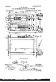
- Figure 1 is an end view of my invention.
- Fig. 2 is a similar view of a portion of my machine, showing the parts in a difierent position.
- Fig. 3 is a top plan view.
- Fig. 4 is a side elevation of my machine.
- Fig. 5 is a perspective view of a part of my machine.
- 1 indicates a jenny-frame, which, as usual, car
- 3 3 designate the fliers; 4 4: indicate the flier-pulleys and 5 5 the capstan-pulleys. 6 6 indicate the tubes and 7 7 the bobbin-pulleys.
- the fliers 3 and pulleys at are connected and move independently of the bobbins and pulleys, as usual.
- the 10 indicates a longitudinal shaft journaled in boxes 11 at the opposite ends of the frame 1.
- This shaft is operatively connected with a belt-shifter 12 and is provided, preferably at a point intermediate of its ends, with a counterweight'ed lever 13, secured thereto in such relative position as to rotate the shaft when the weighted end gravitates from the horizontal position and thereby actuate the shifter to shift the belt from the power-pulley to the loose pulley.
- the brackets 14, in which the boxes 11 are formed are elongated and are provided at their outer ends with a bearing for the pivot-pin 16 of a trip-lever 17, provided with an arm 18 at right angles thereto, hav- 7 ing acurved slot 19, defining a projection or catch 20.
- a lock-lever 21 extending inthe direction of the arm 18 and provided at its extremity with a lug 22, projecting through the slot and co-operating with the catch to sustain the lock-lever in the elevated position or to release it in the manner and for the purpose hereinafter specified.
- a journal-box 23 in which is 'journaled a balance-lever 24, the long arm 25 of which extends nearly to the twine in front of and adjacent to the capstan-pulley.
- the short arm 30 of the balance-lever is provided with graduated apertures 31 for the reception of the stud 32 of a connecting-rod 33, loosely connected at its lower end'with a tilt-lever, by means of which loose connection slight play and motion of the connectingrod and balance-lever is provided for.
- IVhatI claim is- 1.
- the combination with driving mechanism and a belt shifter of trip mechanism to trip the belt shifter actuating mechanism, and mechanism operatively connected with the trip mechanism and belt' shifter actuating mechanism to restore said trip mechanism to its initial position simultaneously with the actuation of the belt shifter, substantially as specified.
- stop mechanism for spinning machines, the combination with driving mechanism and abelt shifter, of acounter-weighted shaft connected with the belt shifter and provided with a lock lever, a balance lever, and a trip lever actuated in one direction by the balance and in the opposite direction by the lock lever, substantially as specified.
- stop mechanism for spinning machines the combination with a balance lever and connected mechanism, of a tilt provided with a curved finger a superimposed spoon end, and a stop, substantially as specified.
Landscapes
- Engineering & Computer Science (AREA)
- Mechanical Engineering (AREA)
- Textile Engineering (AREA)
- Spinning Or Twisting Of Yarns (AREA)
Description
(No Model.) I 2 Sheets-Sheet i. G. H. BLOS3. STOP MECHANISM FOR $PINNING MACHINES.
N0. 545 768; Patented Sept. 3,1895.-
(No Model.) 2 Sheets-Sheet 2.
' G. H. BLOSS. STOP MECHANISM FOR SPINNING MACHINES.
No. 546,768. Patented Sept. 3,18 95'.
Inverfior;
Witnesses;
I ,AMZM W Erica.
CLARENCE H. BLOSS, OF MIAMISBURG, OHIO.
STOP MECHANISM FOR SPINNING-MACHINES.
srncrnlca'rron forming part of Letters Patent No. 545,768, ates September 3, 1895.
Application filed February 25, 1895. Serial No. 539,602. (No model.)
To all whmn it may concern:
Be it known that 1, CLARENCE H. BLoss, of Miamisburg, county of Montgomery, State of Ohio, have invented certain new and useful Improvements in Stop Mechanism for Spinning-Machines, of which thefollowing is a specification, reference being had to the accompanying drawings.
The object of my'invention is to produce mechanism adapted to act with certainty and precision in bringing spinning-machinesas, for example, a-jennyt0 a full stop upon the breakage of the yarn or twine. Heretofore mechanism has been devised for actuating a shifter upon the breakage'of the yarn; but it has been found in practice that after wear such mechanism fails to act by the mere shock of a break in the twine. My mechanism is designed to insure the prompt and certain action of the shifter to drive the belt from the driving-pulley to the loose pulley and stop the machine.
In the accompanying drawings, Figure 1 is an end view of my invention. Fig. 2 is a similar view of a portion of my machine, showing the parts in a difierent position. Fig. 3 is a top plan view. Fig. 4 is a side elevation of my machine. Fig. 5 is a perspective view of a part of my machine.
Referring to the figures on the drawings, 1 indicates a jenny-frame, which, as usual, car
ries on opposite sides of a fender 2 duplicate.
spinning mechanism. 3 3 designate the fliers; 4 4: indicate the flier-pulleys and 5 5 the capstan-pulleys. 6 6 indicate the tubes and 7 7 the bobbin-pulleys. The fliers 3 and pulleys at are connected and move independently of the bobbins and pulleys, as usual.
The parts above described may be of any suitable or ordinary construction and are merely referred to incidentally to illustrate the application of my invention.
8 indicates the twine or yarn which passes continuously into the machine while it is in operation, except for accidentalinterruptionas, for example, when the breakage of the twine occurs. It is for the purpose of stopping the operation of the machine proper when such interruption occurs, in order to prevent the tangling of the twine about the moving parts, as well as to economize the motive power, that my invention is designed.
Coming now to the detail description of the mechanism which constitutes my invention,
10 indicates a longitudinal shaft journaled in boxes 11 at the opposite ends of the frame 1. This shaft is operatively connected with a belt-shifter 12 and is provided, preferably at a point intermediate of its ends, with a counterweight'ed lever 13, secured thereto in such relative position as to rotate the shaft when the weighted end gravitates from the horizontal position and thereby actuate the shifter to shift the belt from the power-pulley to the loose pulley. The brackets 14, in which the boxes 11 are formed, are elongated and are provided at their outer ends with a bearing for the pivot-pin 16 of a trip-lever 17, provided with an arm 18 at right angles thereto, hav- 7 ing acurved slot 19, defining a projection or catch 20. To the extremity of the shaft 10 beyond the bracket I secure a lock-lever 21, extending inthe direction of the arm 18 and provided at its extremity with a lug 22, projecting through the slot and co-operating with the catch to sustain the lock-lever in the elevated position or to release it in the manner and for the purpose hereinafter specified. Preferably in line with the fender I provide a journal-box 23, in which is 'journaled a balance-lever 24, the long arm 25 of which extends nearly to the twine in front of and adjacent to the capstan-pulley.
26 indicates whatI term a twine-tilt, pivoted to the extremity of the arm 25, provided with aspoon end 27,'adapted to lie gently upon the twine, and with a curved finger 28 thereunder which prevents the bouncing of the lever incident to the rapid movement of the twine.
Inasmuch as it may be desired at times to disengage the balance-lever from the twine without stopping the machine, I provide a stop 29 upon the tilt, which permits a disengagement of the lever from the twine by the elevation of its long arm, but which bears against the lever and aifords a rigid connection between the tilt and lever when the parts are sustained bythe twine,
The short arm 30 of the balance-lever is provided with graduated apertures 31 for the reception of the stud 32 of a connecting-rod 33, loosely connected at its lower end'with a tilt-lever, by means of which loose connection slight play and motion of the connectingrod and balance-lever is provided for.
The balance-lever andits connecting parts are so nicely balanced and adjusted that the lever bears with the slightest pressure (and one not sufficient to interfere with the machine proper) upon the twine or yarn. \Vhile this is true the lever is not in perfect equilibrium; but there is constant, though slight, tendency of the lever to gravitate, which tendency is overcome by the resistance of the yarn.
Supposing the machine to be in operation to and the twine for any reason to be severed,
the balance-lever will drop and the trip-lever being thereby actuated through the intermediate mechanism, the latch will be swung out of engagement with the lug upon the lock-ler 5 ver and later will gravitate within the limits prescribed by the slot in the arm 18, the dropping of the lock-lever and the rotation of the shaft being accomplished by the gravitation of the counterweight of the lever 13. It will thus be seen that the instant the resistance of the twine is withdrawn from the balance-lever the lock-lever will be released and the belt-shifter will be actuated to shift the belt and stop the machine through the rotation of the shaft under the impetus of the counter:
weight'lever. It is desirable, however, that when the balance-lever by its gravitation shall have performed its function of tripping the belt-shifter mechanism it shall be re- 0 stored to its elevated position by continuation of the automatic operation, in order that the twine may be readily threaded through the tilt. In order to accomplish this, the slot19 in the arm 18 is so curved that the gravitation 3 5 of the balance-lever will by the rotation of the trip-lever throw said slot forward of the line of the are described by the downward passage of the lug 22 under the impulse of the counterweight. It will be readily observed that this construction will cause the descent 4 5 balancelever when the lock-lever 21 is raised,
a loose connection is provided between the lower end of the connecting-rod 33 and the extremity of the trip-lever. It will be seen that when the lever 21 is raised the lever 17- will also be elevated without depressing the balance-lever, and as soon as the lug 22 arrives opposite the notch 20 the trip-lever 17 will drop back in positive relation with the rod 33, the notch 20 slipping under the lug 22. The
only manual labor then necessary to restore the perfect operation of the machine is the restoration of the continuous strand, threading it through the tilt, and the restoration of the counterweight-lever and lock-lever to '60 their initial positions by the depression of the handle of the former.
IVhatI claim is- 1. In stop mechanism for spinning machines, the combination with driving mechanism, a belt shifter and belt shifter actuating mechanism, of trip mechanism to trip the belt shifter actuating mechanism, and mechanism to restore said trip mechanism to its initial position when displaced, substantially as specified.
2. In stop mechanism for spinning machines, the combination with driving mechanism and a belt shifter, of trip mechanism to trip the belt shifter actuating mechanism, and mechanism operatively connected with the trip mechanism and belt' shifter actuating mechanism to restore said trip mechanism to its initial position simultaneously with the actuation of the belt shifter, substantially as specified.
3. In stop mechanism for spinning machines, the combination with driving mechanism and a belt shifter, of a lever supported normally by the yarn, a belt shifter and intermediate mechanism, and mechanism to restore said lever to its initial position when displaced, substantially as specified.
4. In stop mechanism for spinning machines, the combination with driving mechanism and a belt shifter, of a lever normally supported by the yarn, a trip lever operatively connected with said lever and provided with an elongated slot and catch, a counterweighted shaft operatively connected with the belt shifter and provided with a lock lever cooperating with the catch and slot of the trip lever, substantially as specified.
5. In stop mechanism" for spinning machines, the combination with driving mechanism and abelt shifter, of acounter-weighted shaft connected with the belt shifter and provided with a lock lever, a balance lever, and a trip lever actuated in one direction by the balance and in the opposite direction by the lock lever, substantially as specified.
6. In stop mechanism for spinning machines, the combination with driving mech' anism and a belt shifter, of a balance lever operatively connected with the belt shifter and provided with a pivoted tilt, substantially as specified.
7. In stop mechanism for spinning machines, the combination with a balance lever and connected mechanism, of acurved finger at the extremity of the balance lever and a projecting end above the finger, substantially as specified.
8. In stop mechanism for spinning machines, the combination with a balance lever and connected mechanism, of a pivoted tilt upon the extremity of the balance lever, and a stop upon the tilt, substantially as specified.
9. In stop mechanism for spinning machines, the combination with a balance lever and connected mechanism, of a tilt provided with a curved finger a superimposed spoon end, and a stop, substantially as specified.
In testimony of all which I have hereunto subscribed my name.
CLARENCE H. BLOSS. IVitnesses:
J. O. MYERS,
JAMEs B. SCHENCK.
Publications (1)
| Publication Number | Publication Date |
|---|---|
| US545768A true US545768A (en) | 1895-09-03 |
Family
ID=2614512
Family Applications (1)
| Application Number | Title | Priority Date | Filing Date |
|---|---|---|---|
| US545768D Expired - Lifetime US545768A (en) | Stop mechanism for spinning-machines |
Country Status (1)
| Country | Link |
|---|---|
| US (1) | US545768A (en) |
-
0
- US US545768D patent/US545768A/en not_active Expired - Lifetime
Similar Documents
| Publication | Publication Date | Title |
|---|---|---|
| US116677A (en) | Improvement in stop-motions and creel-stands for knitting-machines | |
| US538537A (en) | Automatic stop mechanism for wool-combing machines | |
| US482930A (en) | Island | |
| US541666A (en) | klots | |
| US452127A (en) | Attachment for warring-machines | |
| US349487A (en) | Stop-motion mechanism for doubling-machines | |
| US595433A (en) | Stop-motion | |
| US534992A (en) | Railway-head | |
| US519295A (en) | Stop-motion | |
| US582991A (en) | Stop-motion for woolen cards | |
| US519463A (en) | Island | |
| US659695A (en) | Doubling-machine. | |
| US519690A (en) | County | |
| US563295A (en) | Island | |
| US269745A (en) | Weft stop-motion for looms | |
| US73399A (en) | smith | |
| US87528A (en) | Improvement in stop-motion mechanism for warping-machine | |
| US166276A (en) | Improvement in stopping mechanisms for drawing-frames | |
| US1225660A (en) | Mule stop-motion. | |
| US723624A (en) | Reeling-machine. | |
| US313869A (en) | And winding yaen oe theead upon bobbins | |
| US288137A (en) | Island | |
| US607360A (en) | Aloysius j | |
| US496938A (en) | Log stop and loader | |
| US597871A (en) | Warping-machine |