US5454236A - Device for treating cut end of knitted fabric on rolling unit of circular knitting machine - Google Patents
Device for treating cut end of knitted fabric on rolling unit of circular knitting machine Download PDFInfo
- Publication number
- US5454236A US5454236A US07/945,131 US94513192A US5454236A US 5454236 A US5454236 A US 5454236A US 94513192 A US94513192 A US 94513192A US 5454236 A US5454236 A US 5454236A
- Authority
- US
- United States
- Prior art keywords
- fabric
- delivery rolls
- reel
- frame
- carried
- Prior art date
- Legal status (The legal status is an assumption and is not a legal conclusion. Google has not performed a legal analysis and makes no representation as to the accuracy of the status listed.)
- Expired - Fee Related
Links
- 239000004744 fabric Substances 0.000 title claims abstract description 101
- 238000009940 knitting Methods 0.000 title claims abstract description 30
- 238000005096 rolling process Methods 0.000 title 1
- 230000005611 electricity Effects 0.000 claims abstract description 7
- 230000003068 static effect Effects 0.000 claims abstract description 7
- 239000002216 antistatic agent Substances 0.000 claims abstract description 3
- 238000004804 winding Methods 0.000 claims abstract 2
- 230000007246 mechanism Effects 0.000 claims description 24
- 239000011248 coating agent Substances 0.000 claims 1
- 238000000576 coating method Methods 0.000 claims 1
- 230000002265 prevention Effects 0.000 abstract 1
- 238000010276 construction Methods 0.000 description 2
- 239000002699 waste material Substances 0.000 description 2
- 239000000835 fiber Substances 0.000 description 1
- 239000007787 solid Substances 0.000 description 1
Images


Classifications
-
- D—TEXTILES; PAPER
- D04—BRAIDING; LACE-MAKING; KNITTING; TRIMMINGS; NON-WOVEN FABRICS
- D04B—KNITTING
- D04B35/00—Details of, or auxiliary devices incorporated in, knitting machines, not otherwise provided for
- D04B35/34—Devices for cutting knitted fabrics
Definitions
- This invention relates to circular knitting machines having fabric take-up mechanisms that wind the knitted fabric produced by the machines upon reels, and that cut the fabric when a preselected amount of fabric has been wound upon each reel.
- the invention more specifically relates to an improved take-up mechanism that reduces if not altogether obviates the possibility of the trailing end portion of the fabric upon the reel being re-engaged and caught up by one of the fabric delivery rolls of the knitting machine during passage of the trailing end portion of the fabric downwardly from such rolls. This in turn reduces the possibility of take-up of the fabric being disrupted.
- fabric knitted into a cylindrical shape by the knitting unit of a circular knitting machine is conducted downwardly from the knitting unit by delivery rolls located beneath it, and is then wound up in a flattened condition on the cylindrical shaft of a reel located below the delivery rolls.
- the fabric rolled upon the shaft of each reel is cut, removed while the reel is unlocked, and is then again rolled at the leading end thereof upon the reel.
- the foregoing operation was performed manually for many years, but is now also performed entirely automatically. Irrespective of whether performed manually or automatically, the fabric becomes less tense when in a rolled condition, and rapidly contracts when cut. This results in the end portion of the fabric moving upwardly and being re-engaged by a delivery roll.
- the present invention provides a fabric take-up mechanism that performs its intended function more efficiently and reliably, and which therefore lessens machine down time and fiber waste.
- the mechanism includes fabric pressing means that engages the fabric passing downwardly from the delivery rolls of the knitting machine and that minimizes the possibility of the fabric being inadvertently re-engaged by the delivery rolls following its downward passage from them.
- the pressing means is a cylindrical shaft that presses the fabric against a delivery roll.
- the mechanism of the invention further includes a fabric guide that is biased for pivotal movement toward the center of the shaft of a reel roll upon which the fabric is wound.
- the fabric guide In order to prevent adherence of the fabric to the fabric guide, it is provided with alternating channels and ridges upon the side thereof facing the creel roll, and preferably is also provided with means for preventing or at least minimizing the possibility of static electricity causing the fabric to adhere to the fabric guide.
- FIG. 1 is an elevational view of a circular knitting machine having a fabric take-up mechanism in accordance with the invention
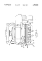
- FIG. 2 is a side view taken in the direction of the arrows 2--2 of FIG. 1 of the fabric take-up mechanism and adjacent components of the knitting machine;
- FIG. 3 is an enlarged side elevational view of delivery rolls of the mechanism and of a therewith associated pressing means of a second embodiment
- FIG. 4 is a fragmentary sectional view, taken substantially along the lines and in the direction of the arrows 4--4 of FIG. 1, through a fabric guide of the mechanism.
- the circular knitting machine 1 shown in FIG. 1 produces knitted fabric (indicated by phantom lines) that is conducted downwardly by delivery rolls 5 (best shown in FIGS. 2 and 3) to a fabric take-up mechanism 8 that includes a reel roll 4 upon which the fabric is wound.
- Mechanism 8 is supported by frame 12 of machine 1 and further includes pressing means for pressing the fabric against one of the delivery rolls 5; a cutting device 2 for cutting the fabric when a desired quantity of it has been wound upon reel roll 4; and a fabric guide 3 for guiding the fabric onto reel roll 4.
- the fabric pressing means includes a cylindrical shaft which illustratively is of solid construction, but which may alternatively be of tubular construction.
- the pressing means further includes a shaft retainer 10 that retains shaft 6 in engagement with the fabric passing over the rightmost (as viewed in FIG. 2) delivery roll 5, while permitting rotative movement of shaft 6 about its central axis.
- the pressing force imposed upon the fabric by roll 6 minimizes the possibility of the cut end of the fabric being re-engaged by one of the delivery rolls as it passes downwardly from the elevation of such rolls.
- the cutting device 2 of mechanism 8 includes a cutter blade 15 driven by a motor 16 that is mounted by a frame member 18 for translatory movement toward and away from the path of travel of the fabric. Such movement is imparted to member 18 at desired times by a drive member 17.
- fabric guide plate 3 is mounted adjacent the lower end of an elongate support member 3' that is pivotally connected adjacent its upper end to an extension of frame 12.
- a spring 13 connected to the upper end of support 3' biases the lower end of support 3' and guide plate 3 toward the fabric being wound upon roll 4.
- the face of the guide that confronts roll 4 has upon it a plurality of alternating ridges A and channels B. These reduce the amount of surface contact between the fabric and guide plate 3.
- a layer of anti-static material 13, or a static electricity discharge device may be provided upon plate 3.
- FIG. 3 shows an additional embodiment of a pressing means 6a for pressing the fabric against delivery roll 5.
- the pressing means 6a consists of a pivotally movable plate 11 that is biased by its own weight into engagement with the fabric passing upon the rightmost (as viewed in FIG. 3) delivery roll 5.
Landscapes
- Engineering & Computer Science (AREA)
- Textile Engineering (AREA)
- Knitting Machines (AREA)
- Treatment Of Fiber Materials (AREA)
- Replacement Of Web Rolls (AREA)
Abstract
Description
Claims (9)
Applications Claiming Priority (2)
| Application Number | Priority Date | Filing Date | Title |
|---|---|---|---|
| JP3-270088 | 1991-09-20 | ||
| JP3270088A JPH0577985A (en) | 1991-09-20 | 1991-09-20 | Processing device for the end of cut knitted fabric in the winding section of a circular knitting machine |
Publications (1)
| Publication Number | Publication Date |
|---|---|
| US5454236A true US5454236A (en) | 1995-10-03 |
Family
ID=17481366
Family Applications (1)
| Application Number | Title | Priority Date | Filing Date |
|---|---|---|---|
| US07/945,131 Expired - Fee Related US5454236A (en) | 1991-09-20 | 1992-09-15 | Device for treating cut end of knitted fabric on rolling unit of circular knitting machine |
Country Status (6)
| Country | Link |
|---|---|
| US (1) | US5454236A (en) |
| EP (1) | EP0533188B1 (en) |
| JP (1) | JPH0577985A (en) |
| DE (1) | DE69211264T2 (en) |
| ES (1) | ES2088066T3 (en) |
| TW (1) | TW212212B (en) |
Cited By (1)
| Publication number | Priority date | Publication date | Assignee | Title |
|---|---|---|---|---|
| KR100326463B1 (en) * | 1999-08-18 | 2002-03-02 | 신익환 | Weaving textile rolling appartatus for spinning machine |
Families Citing this family (5)
| Publication number | Priority date | Publication date | Assignee | Title |
|---|---|---|---|---|
| ITBS20130078A1 (en) * | 2013-05-28 | 2014-11-29 | Santoni & C Spa | DROP AND / OR COLLECTION OF FABRIC FOR CIRCULAR TEXTILE MACHINES FOR TYPE KNIT ¿OPEN¿ |
| ITBS20130077A1 (en) * | 2013-05-28 | 2014-11-29 | Santoni & C Spa | CIRCULAR TEXTILE MACHINE FOR TYPE KNIT ¿OPEN¿ WITH DRAWING GROUP AND FABRIC COLLECTION |
| CN103422249B (en) * | 2013-08-09 | 2016-02-24 | 东阳市双双科技有限公司 | A kind of circular knitting machine cloth roll frame structure |
| CN105155245B (en) * | 2015-10-26 | 2017-11-17 | 丛鑫浩 | A kind of horizontal type fabric cutting machine |
| CN105200756B (en) * | 2015-10-26 | 2018-01-05 | 福建省宏港纺织科技有限公司 | A kind of cutting means of horizontal type fabric cutting machine |
Citations (12)
| Publication number | Priority date | Publication date | Assignee | Title |
|---|---|---|---|---|
| US402551A (en) * | 1889-04-30 | Machine for winding bagging | ||
| US1987141A (en) * | 1930-10-06 | 1935-01-08 | Benjamin A Casper | Winding device |
| US3760609A (en) * | 1971-09-28 | 1973-09-25 | Fouquet Werk Frauz & Planck | Fabric pull-off mechanism, particularly for circular knitting machines |
| US3924395A (en) * | 1973-01-17 | 1975-12-09 | Cogne Macchine Tessili Cognete | Thread suction tube connection |
| US4027506A (en) * | 1975-10-14 | 1977-06-07 | Firma C. Terrot Sohne | Draw-off and take-up arrangement for circular knitting machines |
| US4079600A (en) * | 1975-05-24 | 1978-03-21 | Kabushiki Kaisha Toyoda Jidoshokki Seisakusho | Method and apparatus for doffing fabric rolls from a circular knitting machine |
| US4652252A (en) * | 1983-11-21 | 1987-03-24 | The Gates Rubber Company | Toothed belt and method with reinforcement cord |
| US4667894A (en) * | 1984-10-01 | 1987-05-26 | Kabushiki Kaisha Toka-Rika-Denki-Seisakusho | Webbing lock apparatus |
| US4765157A (en) * | 1986-08-23 | 1988-08-23 | Gunze Limited | Method and apparatus for rolling up fabric for circular knitting machine |
| US4888963A (en) * | 1987-06-04 | 1989-12-26 | Sipra Patententwicklungs | Circular knitting machine |
| US5106896A (en) * | 1988-04-15 | 1992-04-21 | Polyplastics Co, Ltd. | Self-lubricating polyacetal wear part |
| US5224362A (en) * | 1990-09-19 | 1993-07-06 | Precision Fukuhara Works, Ltd. | Apparatus and method for winding and doffing roll of knitted cloth on a circular knitting machine |
-
1991
- 1991-09-20 JP JP3270088A patent/JPH0577985A/en active Pending
- 1991-09-21 TW TW080107492A patent/TW212212B/zh active
-
1992
- 1992-09-15 US US07/945,131 patent/US5454236A/en not_active Expired - Fee Related
- 1992-09-18 DE DE69211264T patent/DE69211264T2/en not_active Expired - Fee Related
- 1992-09-18 EP EP92115995A patent/EP0533188B1/en not_active Expired - Lifetime
- 1992-09-18 ES ES92115995T patent/ES2088066T3/en not_active Expired - Lifetime
Patent Citations (12)
| Publication number | Priority date | Publication date | Assignee | Title |
|---|---|---|---|---|
| US402551A (en) * | 1889-04-30 | Machine for winding bagging | ||
| US1987141A (en) * | 1930-10-06 | 1935-01-08 | Benjamin A Casper | Winding device |
| US3760609A (en) * | 1971-09-28 | 1973-09-25 | Fouquet Werk Frauz & Planck | Fabric pull-off mechanism, particularly for circular knitting machines |
| US3924395A (en) * | 1973-01-17 | 1975-12-09 | Cogne Macchine Tessili Cognete | Thread suction tube connection |
| US4079600A (en) * | 1975-05-24 | 1978-03-21 | Kabushiki Kaisha Toyoda Jidoshokki Seisakusho | Method and apparatus for doffing fabric rolls from a circular knitting machine |
| US4027506A (en) * | 1975-10-14 | 1977-06-07 | Firma C. Terrot Sohne | Draw-off and take-up arrangement for circular knitting machines |
| US4652252A (en) * | 1983-11-21 | 1987-03-24 | The Gates Rubber Company | Toothed belt and method with reinforcement cord |
| US4667894A (en) * | 1984-10-01 | 1987-05-26 | Kabushiki Kaisha Toka-Rika-Denki-Seisakusho | Webbing lock apparatus |
| US4765157A (en) * | 1986-08-23 | 1988-08-23 | Gunze Limited | Method and apparatus for rolling up fabric for circular knitting machine |
| US4888963A (en) * | 1987-06-04 | 1989-12-26 | Sipra Patententwicklungs | Circular knitting machine |
| US5106896A (en) * | 1988-04-15 | 1992-04-21 | Polyplastics Co, Ltd. | Self-lubricating polyacetal wear part |
| US5224362A (en) * | 1990-09-19 | 1993-07-06 | Precision Fukuhara Works, Ltd. | Apparatus and method for winding and doffing roll of knitted cloth on a circular knitting machine |
Cited By (1)
| Publication number | Priority date | Publication date | Assignee | Title |
|---|---|---|---|---|
| KR100326463B1 (en) * | 1999-08-18 | 2002-03-02 | 신익환 | Weaving textile rolling appartatus for spinning machine |
Also Published As
| Publication number | Publication date |
|---|---|
| ES2088066T3 (en) | 1996-08-01 |
| DE69211264T2 (en) | 1996-10-31 |
| DE69211264D1 (en) | 1996-07-11 |
| EP0533188A3 (en) | 1993-08-18 |
| EP0533188A2 (en) | 1993-03-24 |
| EP0533188B1 (en) | 1996-06-05 |
| JPH0577985A (en) | 1993-03-30 |
| TW212212B (en) | 1993-09-01 |
Similar Documents
| Publication | Publication Date | Title |
|---|---|---|
| US4557790A (en) | Tape laminator | |
| US5454236A (en) | Device for treating cut end of knitted fabric on rolling unit of circular knitting machine | |
| US3604652A (en) | Roll sheeter for printing machine | |
| DE3141188A1 (en) | SPINDING MACHINE WITH A MAINTENANCE CART | |
| DE2642183C2 (en) | Thread delivery device, in particular for knitting machines | |
| US6485012B1 (en) | Adjustable indexing roller mechanism | |
| EP0252866A1 (en) | A yarn feed device for textile machines | |
| US3542267A (en) | Method and device for splitting yarn | |
| US4233825A (en) | Knitting machine | |
| GB2127048A (en) | Applying paraffin to yarn | |
| US4660780A (en) | Yarn end finding device | |
| US3067565A (en) | Spinning and twisting apparatus | |
| JP3229387B2 (en) | Apparatus for cleaning the base winding surface of a spindle in a ring spinning or ring twisting machine | |
| JPH08207176A (en) | Apparatus and method for producing label | |
| SK18232002A3 (en) | Assembly and method for cutting strands formed by thermoplastic filaments | |
| JPH06126356A (en) | Coil material feeding device for press machine | |
| US1289938A (en) | Bobbin-stripping machine. | |
| JPH05106145A (en) | Method for treating raising yarn in loom | |
| GB1579654A (en) | Method and apparatus for receiving a thread and transferring it to a bobbin after a bobbin change | |
| US1395223A (en) | Thbead-sprraibtg- machine | |
| GB2047280A (en) | In and for a spooling machine method and apparatus to prevent formation of cut filament pieces | |
| US4462552A (en) | Yarn bobbin winding machine | |
| US3938750A (en) | Strand delay device | |
| US3694871A (en) | Apparatus for processing strand material | |
| EP1445227A1 (en) | Winding station of cross wound package producing textile winding machine |
Legal Events
| Date | Code | Title | Description |
|---|---|---|---|
| AS | Assignment |
Owner name: PRECISION FUKUHARA WORKS, LTD., JAPAN Free format text: ASSIGNMENT OF ASSIGNORS INTEREST.;ASSIGNOR:TANIGUCHI, KOZO;REEL/FRAME:006322/0297 Effective date: 19920901 |
|
| FEPP | Fee payment procedure |
Free format text: PAYOR NUMBER ASSIGNED (ORIGINAL EVENT CODE: ASPN); ENTITY STATUS OF PATENT OWNER: LARGE ENTITY |
|
| FEPP | Fee payment procedure |
Free format text: PAYER NUMBER DE-ASSIGNED (ORIGINAL EVENT CODE: RMPN); ENTITY STATUS OF PATENT OWNER: LARGE ENTITY |
|
| REMI | Maintenance fee reminder mailed | ||
| LAPS | Lapse for failure to pay maintenance fees | ||
| FP | Lapsed due to failure to pay maintenance fee |
Effective date: 19991003 |
|
| FEPP | Fee payment procedure |
Free format text: PAYOR NUMBER ASSIGNED (ORIGINAL EVENT CODE: ASPN); ENTITY STATUS OF PATENT OWNER: LARGE ENTITY |
|
| STCH | Information on status: patent discontinuation |
Free format text: PATENT EXPIRED DUE TO NONPAYMENT OF MAINTENANCE FEES UNDER 37 CFR 1.362 |