US5442481A - Finder optical system in camera - Google Patents
Finder optical system in camera Download PDFInfo
- Publication number
- US5442481A US5442481A US08/105,865 US10586593A US5442481A US 5442481 A US5442481 A US 5442481A US 10586593 A US10586593 A US 10586593A US 5442481 A US5442481 A US 5442481A
- Authority
- US
- United States
- Prior art keywords
- lens
- optical system
- finder
- real image
- ghost
- Prior art date
- Legal status (The legal status is an assumption and is not a legal conclusion. Google has not performed a legal analysis and makes no representation as to the accuracy of the status listed.)
- Expired - Lifetime
Links
Images


Classifications
-
- G—PHYSICS
- G02—OPTICS
- G02B—OPTICAL ELEMENTS, SYSTEMS OR APPARATUS
- G02B23/00—Telescopes, e.g. binoculars; Periscopes; Instruments for viewing the inside of hollow bodies; Viewfinders; Optical aiming or sighting devices
- G02B23/14—Viewfinders
-
- G—PHYSICS
- G02—OPTICS
- G02B—OPTICAL ELEMENTS, SYSTEMS OR APPARATUS
- G02B15/00—Optical objectives with means for varying the magnification
- G02B15/14—Optical objectives with means for varying the magnification by axial movement of one or more lenses or groups of lenses relative to the image plane for continuously varying the equivalent focal length of the objective
- G02B15/144—Optical objectives with means for varying the magnification by axial movement of one or more lenses or groups of lenses relative to the image plane for continuously varying the equivalent focal length of the objective having four groups only
- G02B15/1445—Optical objectives with means for varying the magnification by axial movement of one or more lenses or groups of lenses relative to the image plane for continuously varying the equivalent focal length of the objective having four groups only the first group being negative
- G02B15/144515—Optical objectives with means for varying the magnification by axial movement of one or more lenses or groups of lenses relative to the image plane for continuously varying the equivalent focal length of the objective having four groups only the first group being negative arranged -+++
-
- G—PHYSICS
- G03—PHOTOGRAPHY; CINEMATOGRAPHY; ANALOGOUS TECHNIQUES USING WAVES OTHER THAN OPTICAL WAVES; ELECTROGRAPHY; HOLOGRAPHY
- G03B—APPARATUS OR ARRANGEMENTS FOR TAKING PHOTOGRAPHS OR FOR PROJECTING OR VIEWING THEM; APPARATUS OR ARRANGEMENTS EMPLOYING ANALOGOUS TECHNIQUES USING WAVES OTHER THAN OPTICAL WAVES; ACCESSORIES THEREFOR
- G03B13/00—Viewfinders; Focusing aids for cameras; Means for focusing for cameras; Autofocus systems for cameras
- G03B13/02—Viewfinders
- G03B13/06—Viewfinders with lenses with or without reflectors
-
- G—PHYSICS
- G02—OPTICS
- G02B—OPTICAL ELEMENTS, SYSTEMS OR APPARATUS
- G02B23/00—Telescopes, e.g. binoculars; Periscopes; Instruments for viewing the inside of hollow bodies; Viewfinders; Optical aiming or sighting devices
- G02B23/14—Viewfinders
- G02B23/145—Zoom viewfinders
Definitions
- the present invention relates to a finder optical system in a camera. More precisely, the invention relates to a ghost image preventing optical system in a finder optical system which is separate from a photographing optical system.
- the photographing optical system and the finder optical system are constituted by the same optical system.
- the photographing optical system is usually provided with an anti-reflection layer (hereinafter referred to as AFL) to prevent a ghost image from occurring. Consequently, in a single lens reflex camera, a ghost image will not occur in the finder optical system.
- AFL anti-reflection layer
- the photographing optical system is subject to anti-reflection surface treatment to prevent a ghost image, similar to the single lens reflex camera, but nothing is done to prevent a ghost image from occurring in the finder optical system.
- the reason for this being that when light emitted from an eyepiece (i.e., ocular lens) in the finder optical system is incident upon viewer's eyes, the viewer usually does not see a ghost image, since the human eye naturally eliminates most ghost images.
- Synthetic resin lenses usually have a refractive index of 1.5 ⁇ 1.6 lower than other common optical elements. Consequently, in the finder optical system having a small reflectance and made of synthetic resin lenses, the ghost image is usually not apparent.
- the diameter of the lenses on the objective side in recent real image type finder optical systems is made larger than that of conventional finder optical systems to realize a wider angle lens. This results in light from outside of the field of view falling into the finder optical system, particularly at high magnification (i.e., high power).
- the invention is directed towards the elimination of ghost images in real image type finder optical systems in which the finder optical system is separate from the photographing optical system.
- the objective optical system comprises first and second lens assemblies (the order of lens assemblies hereinafter considered from the object side of the finder) in the optical axis direction, and the first lens group includes a lens made of synthetic resin, according to the preferred embodiment of the present invention, at least one lens surface thereof is coated with an AFL.
- the objective lens includes more than one (i.e., front and rear) lens assemblies, it is preferable that at least one lens surface of the synthetic resin lens of the first lens group or at least one lens surface of the synthetic resin lens of the second lens group is coated with an AFL.
- the synthetic resin lens to be coated with the AFL has the largest refractive index. Accordingly, if the objective optical system includes synthetic resin lenses made of acrylic resin and polycarbonate, the anti-reflection coating is preferably provided on the polycarbonate lens rather than the acrylic lens.
- the synthetic resin lens to be coated with the AFL has a negative power.
- a material whose Abbe number is small has a high refractive index and a material whose Abbe number is large has a low refractive index. Consequently, taking the chromatic aberration into account, it is preferable that, of those lenses that cause the ghost image, the negative power synthetic resin lens is coated with an AFL.
- the two specific lens surfaces are preferably the first and second lens surfaces of the first synthetic resin lens of the first lens group.
- the two specific lens surfaces can be the second lens surfaces of the first synthetic resin lens of the first lens group and the second lens surfaces of the second synthetic resin lens of the first lens group.
- the AFL is not limited to a specific material.
- MgF 2 or SiO 2 can be used.
- FIG. 1 is a conceptual view of a real image type of finder optical system to which the present invention is applied;
- FIG. 2 shows an arrangement of optical elements of a real image type zoom finder in a wide angle position
- FIG. 3 shows an arrangement of optical elements of a real image type of zoom finder optical system, in a telephoto position
- FIG. 4 is a schematic view of an optical path in the optical arrangement shown in FIG. 3, in a first position in which a ghost image occurs;
- FIG. 5 is a schematic view of an optical path in the optical arrangement shown in FIG. 3, in a second position in which a ghost image occurs;
- FIG. 6 is a schematic view of an optical path in the optical arrangement shown in FIG. 3, in a third position in which a ghost image occurs;
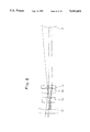
- FIG. 7 is a schematic view of an optical path in the optical arrangement shown in FIG. 3, in a fourth position in which a ghost image occurs;
- FIG. 8 is a schematic view of an optical path in the optical arrangement shown in FIG. 3, in a fifth position in which a ghost image occurs;
- FIG. 9 is an illustrative view showing an AFL applied to a lens surface of the optical arrangement shown in FIG. 3 according to a first embodiment of the present invention.
- FIG. 10 is an illustrative view showing AFL applied to lens surfaces of the optical arrangement shown in FIG. 3 according to a second embodiment of the present invention.
- FIG. 11 is an illustrative view showing AFL applied to lens surfaces of the optical arrangement shown in FIG. 3 according to a third embodiment of the present invention.
- FIG. 1 shows a basic structure of a real image type of zoom finder to which the present invention is applied.
- the zoom finder is comprised of an objective lens system, including a first lens group A having negative power, a second lens group B having positive power, and a third lens group C having positive power, and an ocular optical system including an image inverting optical system D and a fourth lens group E having a positive power.
- a real image to be formed by the objective lens optical system is formed in the vicinity of the third lens C, and is then inverted in both the horizontal and vertical directions by the image inverting optical system D of the ocular optical system, so that an erect image can be viewed through the fourth lens group E.
- the zooming can be carried out by the movement of the first and second lens assemblies A and B in the optical axis direction in a predetermined relative relationship.
- FIGS. 2 and 3 show a more practical arrangement of the optical elements of the real image type of zoom finder shown in FIG. 1, at a wide angle position and a telephoto position, respectively.
- the first lens group A of the objective optical system is comprised of a first lens L1 and a second lens L2.
- the second lens group B is comprised of a third lens L3 and a fourth lens L4
- the third lens group C is comprised of a fifth lens L5 and a sixth lens L6, respectively.
- the image formed by the objective optical system is formed on a second lens surface of the sixth lens L6 or in the vicinity thereof.
- the image inverting optical system D is made of a Porro prism.
- the fourth lens group E is made of a seventh lens L7 and an eighth lens L8, respectively.
- FIGS. 4 through 8 and Table 1 below show the results of the analysis.
- the ghost image "b" can be prevented by coating the first lens surface of the first lens L1.
- all of the ghost images "a” through “e” can be eliminated or weakened.
- This embodiment also serves to eliminate or weaken all of the ghost images "a” through “e”.
- the occurrence of the ghost image "b" can be more effectively prevented when the first lens surface of the first lens L1 is coated than when the second lens surface of the second lens L2, whose refractive index is lower than that of the first lens surface of the first lens L1, is coated, since there is no significant difference in incident angle of light between the first lens surface of the first lens L1 and the second lens surface of the second lens L2, as can be seen in the drawings.
- Tables 2 and 3 show lens data of a real image type of zoom finder shown in FIGS. 2 and 3, respectively.
- the lenses are all made of synthetic resin.
- Aspherical lens data is as follows.
- a camera having a real image type of finder optical system separate from a photographing optical system wherein a clear real image formed by an objective optical system can be observed through an ocular optical system without being obstructed by a ghost image.
Landscapes
- Physics & Mathematics (AREA)
- General Physics & Mathematics (AREA)
- Optics & Photonics (AREA)
- Astronomy & Astrophysics (AREA)
- Lenses (AREA)
Abstract
Description
              TABLE 1
______________________________________
LENS         L1      L2        L3    L4
REFRACTIVE   1.58547 1.49176   1.49176
                                     1.58547
INDEX
LENS         1     2      1   2    1   2    1   2
SURFACE
GHOST a            ◯
                          ◯
(FIG.4)
GHOST b      ◯    ◯
(FIG.5)
GHOST c            ◯   ◯
(FIG.6)
GHOST d            ◯            ◯
(FIG.7)
GHOST e            ◯                ◯
(FIG.8)
FREQUENCY    1     4      1   2    1   0    1   1
OF
OCCURRENCE
______________________________________
              TABLE 2
______________________________________
               Wide-angle
                         Telephoto
______________________________________
Finder Magnification
                 0.34 times  0.87 times
Diopter (3 m)    -0.99 dp    -0.94 dp
Real field of View (2ω)
                 38.6°
                             15.0°
______________________________________
              TABLE 3
______________________________________
No      r.sub.No  D.sub.No      n     ν
______________________________________
1*      -99.033   1.50          1.58547
                                      29.9
2*      26.607    2.88          --
3*      31.670    1.90          1.49176
                                      57.4
4*      10.116    13.25(WIDE)   --
˜1.72(TELE)
5*      10.744    2.17          1.49176
                                      57.4
6       -7.033    0.10          --
7*      -11.065   1.00          1.58547
                                      29.9
8*      -28.387   11.67(WIDE)   --
˜23.24(TELE)
9*       6.392    2.33          1.49176
                                      57.4
10       7.326    2.26          --
11*     10.981    1.59          1.49176
                                      57.4
12      ∞   6.80          --
13      ∞   23.00         1.49176
                                      57.4
14      ∞   1.40
15      15.499    2.71          1.49176
                                      57.4
16*     -25.133   1.70          --
17      13.317    2.21          1.58547
                                      29.9
18      10.000    --            --
______________________________________
 Note:
 "*" designates an aspherical lens surface.
x=cy.sup.2 /[1+{1-(1+K)c.sup.2 y.sup.2 }.sup.1/2 ]+A4y.sup.4 +A6y.sup.6 +A8y.sup.8
Claims (5)
Applications Claiming Priority (2)
| Application Number | Priority Date | Filing Date | Title |
|---|---|---|---|
| JP21918592 | 1992-08-18 | ||
| JP4-219185 | 1993-07-15 |
Publications (1)
| Publication Number | Publication Date |
|---|---|
| US5442481A true US5442481A (en) | 1995-08-15 |
Family
ID=16731537
Family Applications (1)
| Application Number | Title | Priority Date | Filing Date |
|---|---|---|---|
| US08/105,865 Expired - Lifetime US5442481A (en) | 1992-08-18 | 1993-08-11 | Finder optical system in camera |
Country Status (1)
| Country | Link |
|---|---|
| US (1) | US5442481A (en) |
Cited By (6)
| Publication number | Priority date | Publication date | Assignee | Title |
|---|---|---|---|---|
| US5815747A (en) * | 1995-12-28 | 1998-09-29 | Olympus Optical Co., Ltd. | Camera having autofocus function independent of photographing optical system |
| US6011648A (en) * | 1997-05-15 | 2000-01-04 | Minolta Co., Ltd. | Optical system having an optical element made of resin |
| US6278544B1 (en) | 1999-04-08 | 2001-08-21 | Asahi Kogaku Kogyo Kabushiki Kaisha | Real-image zoom finder optical system |
| US20030210468A1 (en) * | 2002-05-07 | 2003-11-13 | Yumiko Kato | Observation optical system and optical apparatus |
| US20050013004A1 (en) * | 2003-07-14 | 2005-01-20 | Konica Minolta Holdings, Inc. | Forming methods, forming devices for articles having a micro-sized shape and optical elements |
| US20050124348A1 (en) * | 2003-11-26 | 2005-06-09 | Peter Gaal | Code channel management in a wireless communications system |
Citations (17)
| Publication number | Priority date | Publication date | Assignee | Title |
|---|---|---|---|---|
| US3971951A (en) * | 1973-10-17 | 1976-07-27 | Nippon Kogaku K.K. | Apparatus for measuring two different fluorescences of a sample |
| US4240701A (en) * | 1978-06-12 | 1980-12-23 | M.U. Engineering & Manufacturing, Inc. | All plastic projection lens assembly with aspheric surface |
| US4240704A (en) * | 1977-11-29 | 1980-12-23 | Olympus Optical Co., Ltd. | Objective for video disks |
| US4367927A (en) * | 1977-07-23 | 1983-01-11 | Olympus Optical Co., Ltd. | Zoom lens system |
| US4725130A (en) * | 1985-03-20 | 1988-02-16 | Ricoh Company, Ltd. | Zoom finder |
| US4779969A (en) * | 1985-07-03 | 1988-10-25 | Canon Kabushiki Kaisha | Finding device of variable magnification |
| US4784467A (en) * | 1986-02-18 | 1988-11-15 | Minolta Camera Kabushiki Kaisha | Multi-layered anti-reflection coating |
| US4812023A (en) * | 1986-02-21 | 1989-03-14 | Olympus Optical Co., Ltd. | Zoom finder |
| US4842395A (en) * | 1984-12-27 | 1989-06-27 | Canon Kabushiki Kaisha | Finder of variable magnification |
| US4854680A (en) * | 1987-03-11 | 1989-08-08 | Olympus Optical Co., Ltd. | Zoom view finder |
| US4909615A (en) * | 1987-05-29 | 1990-03-20 | Minolta Camera Kabushiki Kaisha | Zoom lens system for use in an image projecting apparatus with kohler illumination |
| US4963005A (en) * | 1986-05-14 | 1990-10-16 | Canon Kabushiki Kaishi | Zoom lens having built-in diaphragm |
| US4992809A (en) * | 1988-10-28 | 1991-02-12 | Asahi Kogaku Kogyo Kabushiki Kaisha | Zoom finder system |
| GB2241082A (en) * | 1990-02-14 | 1991-08-21 | Asahi Optical Co Ltd | Real Image type finder |
| US5052787A (en) * | 1988-10-26 | 1991-10-01 | Asahi Kogaku Kogyo K.K. | Zoom finder |
| US5086353A (en) * | 1988-04-07 | 1992-02-04 | Minolta Camera Kabushiki Kaisha | Variable magnification viewfinder optical system |
| US5193028A (en) * | 1990-09-11 | 1993-03-09 | Asahi Kogaku Kogyo Kabushiki Kaisha | Optical system for eliminating ghost image in wide wavelength band |
-
1993
- 1993-08-11 US US08/105,865 patent/US5442481A/en not_active Expired - Lifetime
Patent Citations (17)
| Publication number | Priority date | Publication date | Assignee | Title |
|---|---|---|---|---|
| US3971951A (en) * | 1973-10-17 | 1976-07-27 | Nippon Kogaku K.K. | Apparatus for measuring two different fluorescences of a sample |
| US4367927A (en) * | 1977-07-23 | 1983-01-11 | Olympus Optical Co., Ltd. | Zoom lens system |
| US4240704A (en) * | 1977-11-29 | 1980-12-23 | Olympus Optical Co., Ltd. | Objective for video disks |
| US4240701A (en) * | 1978-06-12 | 1980-12-23 | M.U. Engineering & Manufacturing, Inc. | All plastic projection lens assembly with aspheric surface |
| US4842395A (en) * | 1984-12-27 | 1989-06-27 | Canon Kabushiki Kaisha | Finder of variable magnification |
| US4725130A (en) * | 1985-03-20 | 1988-02-16 | Ricoh Company, Ltd. | Zoom finder |
| US4779969A (en) * | 1985-07-03 | 1988-10-25 | Canon Kabushiki Kaisha | Finding device of variable magnification |
| US4784467A (en) * | 1986-02-18 | 1988-11-15 | Minolta Camera Kabushiki Kaisha | Multi-layered anti-reflection coating |
| US4812023A (en) * | 1986-02-21 | 1989-03-14 | Olympus Optical Co., Ltd. | Zoom finder |
| US4963005A (en) * | 1986-05-14 | 1990-10-16 | Canon Kabushiki Kaishi | Zoom lens having built-in diaphragm |
| US4854680A (en) * | 1987-03-11 | 1989-08-08 | Olympus Optical Co., Ltd. | Zoom view finder |
| US4909615A (en) * | 1987-05-29 | 1990-03-20 | Minolta Camera Kabushiki Kaisha | Zoom lens system for use in an image projecting apparatus with kohler illumination |
| US5086353A (en) * | 1988-04-07 | 1992-02-04 | Minolta Camera Kabushiki Kaisha | Variable magnification viewfinder optical system |
| US5052787A (en) * | 1988-10-26 | 1991-10-01 | Asahi Kogaku Kogyo K.K. | Zoom finder |
| US4992809A (en) * | 1988-10-28 | 1991-02-12 | Asahi Kogaku Kogyo Kabushiki Kaisha | Zoom finder system |
| GB2241082A (en) * | 1990-02-14 | 1991-08-21 | Asahi Optical Co Ltd | Real Image type finder |
| US5193028A (en) * | 1990-09-11 | 1993-03-09 | Asahi Kogaku Kogyo Kabushiki Kaisha | Optical system for eliminating ghost image in wide wavelength band |
Cited By (11)
| Publication number | Priority date | Publication date | Assignee | Title |
|---|---|---|---|---|
| US5815747A (en) * | 1995-12-28 | 1998-09-29 | Olympus Optical Co., Ltd. | Camera having autofocus function independent of photographing optical system |
| US6215959B1 (en) | 1995-12-28 | 2001-04-10 | Olympus Optical Co., Ltd. | Camera having autofocus function independent of photographing optical system |
| US6011648A (en) * | 1997-05-15 | 2000-01-04 | Minolta Co., Ltd. | Optical system having an optical element made of resin |
| US6278544B1 (en) | 1999-04-08 | 2001-08-21 | Asahi Kogaku Kogyo Kabushiki Kaisha | Real-image zoom finder optical system |
| US20030210468A1 (en) * | 2002-05-07 | 2003-11-13 | Yumiko Kato | Observation optical system and optical apparatus |
| US7035022B2 (en) * | 2002-05-07 | 2006-04-25 | Canon Kabushiki Kaisha | Observation optical system and optical apparatus |
| US20050013004A1 (en) * | 2003-07-14 | 2005-01-20 | Konica Minolta Holdings, Inc. | Forming methods, forming devices for articles having a micro-sized shape and optical elements |
| US7212340B2 (en) * | 2003-07-14 | 2007-05-01 | Konica Minolta Holdings, Inc. | Forming methods, forming devices for articles having a micro-sized shape and optical elements |
| US20070107469A1 (en) * | 2003-07-14 | 2007-05-17 | Konica Minolta Holdings, Inc. | Forming methods, forming devices for articles having a micro-sized shape and optical elements |
| US7365919B2 (en) | 2003-07-14 | 2008-04-29 | Konica Minolta Holdings, Inc. | Forming methods, forming devices for articles having a micro-sized shape and optical elements |
| US20050124348A1 (en) * | 2003-11-26 | 2005-06-09 | Peter Gaal | Code channel management in a wireless communications system |
Similar Documents
| Publication | Publication Date | Title |
|---|---|---|
| US5541773A (en) | Two-unit zoom lens system | |
| US5253112A (en) | Rear conversion lens | |
| US5630188A (en) | Lighting type bright frame finder | |
| JPH02109009A (en) | Keplerian zoom finder optical system | |
| JP3064337B2 (en) | Real image type variable magnification finder optical system | |
| US20020126393A1 (en) | Variable-focus lens system | |
| JP2000111798A (en) | Zoom lens | |
| US5748381A (en) | Real image type zoom finder optical system | |
| US5627677A (en) | Rear conversion lens with vibration-reduction function | |
| US5442481A (en) | Finder optical system in camera | |
| JP2820240B2 (en) | Zoom finder | |
| US5438455A (en) | Internal focus telephoto lens for an auto focus camera | |
| US6661584B2 (en) | Zoom lens and camera having the zoom lens | |
| US6847482B2 (en) | Image-erecting viewing optical system | |
| JP3311090B2 (en) | Real image finder | |
| US5815312A (en) | Real image type finder | |
| US5642230A (en) | Zoom finder | |
| JPH0772390A (en) | Small zoom lens | |
| US6335827B2 (en) | Real image mode variable magnification finder | |
| JP3122974B2 (en) | Small zoom lens | |
| JP3766257B2 (en) | Viewfinder optical system | |
| US4427268A (en) | Variable magnification ratio lens | |
| US6038069A (en) | Real image type zoom finder | |
| US6545820B2 (en) | Zoom lens system | |
| JPS61210316A (en) | Albada type viewfinder optical system |
Legal Events
| Date | Code | Title | Description |
|---|---|---|---|
| AS | Assignment |
Owner name: ASAHI KOGAKU KOGYO KABUSHIKI KAISHA Free format text: ASSIGNMENT OF ASSIGNORS INTEREST;ASSIGNOR:HASUSHITA, SACHIO;REEL/FRAME:006657/0189 Effective date: 19930810 |
|
| STCF | Information on status: patent grant |
Free format text: PATENTED CASE |
|
| CC | Certificate of correction | ||
| FEPP | Fee payment procedure |
Free format text: PAYOR NUMBER ASSIGNED (ORIGINAL EVENT CODE: ASPN); ENTITY STATUS OF PATENT OWNER: LARGE ENTITY |
|
| FPAY | Fee payment |
Year of fee payment: 4 |
|
| FPAY | Fee payment |
Year of fee payment: 8 |
|
| FPAY | Fee payment |
Year of fee payment: 12 |
|
| AS | Assignment |
Owner name: HOYA CORPORATION, JAPAN Free format text: MERGER;ASSIGNOR:ASAHI KOGAKU KOGYO KABUSHIKI KAISHA;REEL/FRAME:026970/0621 Effective date: 20080331 |
|
| AS | Assignment |
Owner name: PENTAX RICOH IMAGING COMPANY, LTD., JAPAN Free format text: CORPORATE SPLIT;ASSIGNOR:HOYA CORPORATION;REEL/FRAME:027315/0115 Effective date: 20111003 |