US5441173A - Piston depositor - Google Patents
Piston depositor Download PDFInfo
- Publication number
- US5441173A US5441173A US08/205,204 US20520494A US5441173A US 5441173 A US5441173 A US 5441173A US 20520494 A US20520494 A US 20520494A US 5441173 A US5441173 A US 5441173A
- Authority
- US
- United States
- Prior art keywords
- piston
- valve
- drive
- servomotor
- depositor
- Prior art date
- Legal status (The legal status is an assumption and is not a legal conclusion. Google has not performed a legal analysis and makes no representation as to the accuracy of the status listed.)
- Expired - Fee Related
Links
- 238000000151 deposition Methods 0.000 abstract description 3
- 230000000694 effects Effects 0.000 description 3
- 238000012423 maintenance Methods 0.000 description 3
- 230000009969 flowable effect Effects 0.000 description 2
- 239000003112 inhibitor Substances 0.000 description 2
- 238000010926 purge Methods 0.000 description 2
- 230000002411 adverse Effects 0.000 description 1
- 235000015173 baked goods and baking mixes Nutrition 0.000 description 1
- 238000004140 cleaning Methods 0.000 description 1
- 239000000463 material Substances 0.000 description 1
- 238000012986 modification Methods 0.000 description 1
- 230000004048 modification Effects 0.000 description 1
- 235000012459 muffins Nutrition 0.000 description 1
- 230000007935 neutral effect Effects 0.000 description 1
- 229920003023 plastic Polymers 0.000 description 1
- 238000007789 sealing Methods 0.000 description 1
- 230000032258 transport Effects 0.000 description 1
- 229920000785 ultra high molecular weight polyethylene Polymers 0.000 description 1
Images


Classifications
-
- A—HUMAN NECESSITIES
- A21—BAKING; EDIBLE DOUGHS
- A21C—MACHINES OR EQUIPMENT FOR MAKING OR PROCESSING DOUGHS; HANDLING BAKED ARTICLES MADE FROM DOUGH
- A21C5/00—Dough-dividing machines
-
- A—HUMAN NECESSITIES
- A21—BAKING; EDIBLE DOUGHS
- A21C—MACHINES OR EQUIPMENT FOR MAKING OR PROCESSING DOUGHS; HANDLING BAKED ARTICLES MADE FROM DOUGH
- A21C9/00—Other apparatus for handling dough or dough pieces
- A21C9/08—Depositing, arranging and conveying apparatus for handling pieces, e.g. sheets of dough
Definitions
- the present invention relates to bakery equipment and, more particularly, to a batter depositor for an automated bakery system.
- Automated bakery systems may include a belt conveyor which transports pans past a batter deposit station.
- a flowable batter for example, may be held in a hopper located at the deposit station.
- a depositor controls flow of batter from the hopper to pans stepped past the deposit station on the conveyor.
- the pans are filled to the proper level with the batter and stepped down the conveyor to subsequent operations, such as past a crumb depositor, until the pans are delivered to an oven. After the product is properly baked, it is removed from the pans.
- the pans are cleaned and reloaded at the entrance end of the system.
- batter depositors include a hopper, a rotary valve and a piston which is moved through intake and deposit strokes in timed relationship with movement of the rotary valve.
- a rotary valve in a first position wherein the hopper will communicate with a piston cylinder, the piston may be drawn through its intake stroke.
- the valve is then rotated to cutoff flow of batter into the cylinder and to place the cylinder into communication with an outlet or discharge opening.
- the piston may then be moved through its discharge stroke depositing batter into a pan positioned below the depositor.
- Proper timing in the operation of the valve and piston drive is critical to proper operation of the depositor.
- the scaling weight or amount of batter deposited by the device is controlled by the piston intake stroke and by the timing of the positioning of the valve. Rotation of the valve to the discharge position cuts off communication with or flow of the batter to the cylinder.
- a batter depositor including a valve housing, a rotary valve and a piston.
- a programmable piston drive and a programmable rotary valve drive are also provided.
- the drives permit effective control over the system parameters and operation. Variations can be achieved in the speed of the piston and over the length of intake stroke to control deposit weights.
- the rotary valve positioning, timing and speed may be accurately controlled.
- programmable servomotors are used to operate the valve and the piston.
- the valve drive includes a servomotor having a rotary output shaft connected to a valve crank arrangement through a precision gearhead or reduction gearbox.
- the piston drive includes a programmable servomotor which drives a rack and pinion subassembly through another precision gearhead or reduction gearbox.
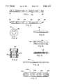
- FIG. 1 is a perspective view of a piston depositor in accordance with the present invention
- FIG. 2 is an enlarged, cross-sectional view taken generally along line II--II of FIG. 1 with a rotary valve incorporated therein shown in the intake position;
- FIG. 3 is another cross-sectional view also taken generally along line II--II of FIG. 1 with the valve shown in the deposit position;
- FIG. 4 is a top view of a valve housing incorporated in the present invention.
- FIG. 5 is a bottom view of the valve housing
- FIG. 6 is a rear view of the valve housing
- FIG. 7 is an end, elevational view of the valve housing
- FIG. 8 is a fragmentary, enlarged view of the rotary valve
- FIG. 9 is an enlarged, rear view of the piston incorporated in the present invention.
- FIG. 10 is an elevational view of the piston of FIG. 9;
- FIG. 11 is a top view of a piston rod connecting bar incorporated in the present invention.
- FIG 12 is an elevational view of the bar of FIG. 11;
- FIG. 13 is a top view of a piston drive rack incorporated in the present invention.
- FIG. 14 is a elevational view of the rack of FIG. 13;
- FIG. 15 is a bottom view of the rack of FIG. 13;
- FIG. 16 is a side view of a product die which may be used with the depositor
- FIG. 17 is a bottom view of the die of FIG. 16;
- FIG. 18 is an electrical schematic of the drive motors and control system incorporated in the present invention.
- FIG. 19 is a view of the control panel for the depositor.
- FIGS. 1, 2 and 3 A piston depositor in accordance with the present invention is illustrated in FIGS. 1, 2 and 3 and generally designated by the numeral 10.
- Depositor 10 includes a valve housing 14, a rotary valve 16, a piston and piston drive assembly 18, a valve drive motor subassembly 20 and a piston drive motor subassembly 22.
- Motors 20, 22 are electrically interconnected and controlled through a system which includes a panel 24.
- Depositor 10 is adapted for use with a flowable or pourable batter.
- a hopper 26 for the batter is mounted on valve housing 14.
- Valve housing 14, as seen in FIGS. 2-7, is generally rectangular in configuration.
- the housing defines a series of generally circular inlets 32, 34, 36 and 38 in a top surface 14.
- Hopper 26 defines an outlet 40 aligned with the inlets.
- the inlets intersect an enlarged cylindrical valve chamber 42.
- a lower surface 46 of housing 14 defines spaced outlets 48, 50.
- Outlets 48, 50 open through a generally rectangular recess 52 formed in the lower surface of the valve housing.
- a plurality of cylindrical bores 58, 60, 62 and 64 extend perpendicular to valve chamber 42.
- Rotary valve 16 as seen in FIGS. 2, 3 and 8, is an elongated, cylindrical member which defines a plurality of generally L-shaped passages 70.
- Each passage 70 includes a circular inlet 72 which communicates with an outlet 74.
- Valve 14 further includes grooves 76 adjacent each end for receiving an O-ring seal 78.
- a coupler shaft 80 extends from an end of the rotary valve.
- Valve 16 is rotatable within valve chamber 42.
- Valve passages 70 are alignable with the valve housing inlets 32, 34, 36 and 38 and the cylinder bores 58, 60, 62 and 64.
- a piston subassembly is disposed within each of the bores 58, 60, 62 and 64. For simplicity sake, only one piston subassembly is illustrated in FIG. 1.
- Each subassembly includes a piston 92 attached to a piston rod 94.
- piston 92 defines a connecting bore 96 intersected by a cross bore 98.
- Rod 94 extends into bore 96 and is attached thereto by a suitable pin extending through bore 98.
- the piston defines a series of sealing flanges or rings 102 separated by grooves 104.
- the piston is preferably fabricated from a UHMW plastic material.
- Each piston rod 94 is connected to a cross rod or connecting bar 106.
- Bar 106 defines a plurality of spaced rod bores 108.
- Rods 94 are secured to bar 106 by suitable pins or fasteners at bores 108.
- Connecting bar 106 is supported in side plates or support frame members 110 which extend alongside of the valve housing 14. Supports 110 define grooves or guideways 112.
- Each end 114 of connecting bar 106 is secured to a rack 116, which is slideably positioned within one of the guideways 112.
- each rack 116 defines a plurality of gear teeth 118 and a notched connector end 120.
- Connector tabs 122 at the ends 114 of bar 106 slip into notches 120, and the bar is connected to the rack by a suitable fastener.
- Racks 116 and connecting bar 106 are reciprocated on supports 110 by drive subassembly 22.
- the drive subassembly includes a shaft 130 which extends between supports 110 and is rotatably mounted thereon by suitable bearings.
- Pinion gears 132 are secured to shaft 130 at each end thereof and in a position to engage the racks 116.
- Shaft 130 and the pinions are alternately rotated to reciprocate connecting bar 106 and, hence, move pistons 92 through their intake and deposit cycle.
- Drive 22 further includes a servomotor 136.
- Servomotor 136 has an output shaft coupled to a gearhead or reduction gearbox 138.
- An output shaft from gearbox 138 is coupled to shaft 130.
- Valve 16 is moveable from a first position, shown in FIG. 2, wherein valve passages: 70 connect each of the cylinder bores with the batter hopper through the inlets. Rotation of the valve through an angle of 45-degrees will move passages 70 to a discharge or deposit position, as shown in FIG. 3.
- the cylinders When in the discharge position, the cylinders are placed in communication with discharge openings or outlets 48, 50 of the valve housing.
- the valve is rotated between these two positions by a servomotor 152.
- Servomotor 152 includes an output shaft which is connected to a crank arm 154 through a gearhead or reduction gearbox 156.
- a second crank arm 158 is nonrotatably connected to the coupler 80 on the end of valve 16. Cranks 154, 158 are connected by a connecting rod 162.
- valve drive subassembly 20 When valve drive subassembly 20 positions the cranks 154, 158 as shown in FIG. 2, the valve is in the intake position. Piston drive subassembly 22 can then shift connecting bar 106 and pistons 92 to the right, as viewed in FIG. 2, through the length of an intake stroke. Batter will flow from hopper 26 through the inlets in the housing and the valve passages to fill the individual piston cylinders 58, 60, 62 and 64.
- Servomotor 152 is actuated to rotate cranks 154, 158 to the position shown in FIG. 3.
- Valve 16 is now positioned so that inlets 72 are aligned with the cylinders, and outlets 74 are aligned with the valve housing outlets 48, 50.
- Servomotor 136 is then actuated to shift pistons 92 towards valve 16 on their discharge stroke, thereby forcing the batter from the cylinders and through the discharge openings to bakery pans positioned below the valve housing.
- the servomotors 136, 152 are operated through a control system, as schematically illustrated in FIGS. 18 and 19.
- the control system includes a piston drive deposit speed indicator 182 having a digital output on panel 24.
- the system also includes a piston drive scaling weight indicator 184.
- the scaling weight indicator provides an indication of the intake stroke length for each of the pistons.
- the control system further includes a rotary valve return speed indicator 186 and a rotary valve fill speed indicator 188.
- the indicators show the speed of rotation of the valve between the first and second position and the second and first position.
- Servomotors 136, 152 are electrically inter-connected through electrical lines 190, 192. The interconnection controls the timing of servomotor operation. Servomotor 136 cannot drive the pistons to discharge batter unless the valve is in the discharge position.
- the electrical system further includes limit sensors 194, 196 which sense the clockwise and counterclockwise rotational limits of pinion gears 132.
- the system further includes a home sensor 198. The sensors prevent driving of the pistons against the end of their cylinders or full retraction out of their cylinders.
- a three-position piston drive switch 200 is mounted on panel 24 and connected to servomotor 136. As shown in FIG. 19, switch 200 is moveable between run, purge and clean positions. When in the clean position, the piston bar is moved back a specified amount of steps to permit the pistons to be removed from their cylinder bores for cleaning purposes. When in the center run position, the servomotor is allowed to run the specified programs for deposit operation. When in the purge position, the system may be cycled manually.
- the system further includes three-position switches 204, 206 which set the piston scaling weight or stroke length and the return stroke or piston deposit speed. Each of the switches is moveable to an "increase” position or a “decrease” position.
- the valves selected will step up or down on indicators 182, 184. When in the center or neutral position, the selected valves are run to operate servomotor 136.
- the electrical controls for the rotary valve drive servomotor 152 are similar.
- the system includes clockwise and counterclockwise limit sensors 208, 210 and a home sensor 212.
- the sensors control the maximum angular rotation of the valve.
- Three-position switches 214, 216 provide control over the rotary valve return speed (rotation from the deposit position to the fill position) and the rotary valve deposit speed (rotation from the fill position to the deposit position), respectively.
- the control system as seen in FIG. 19, further includes a main power/emergency stop switch 220 and a depositor inhibitor switch 222. Inhibitor switch 222 will start and stop the depositor allowing the bakery conveyor and other apparatus to run if needed.
- the main switch 222 allows the operator to stop the depositing system immediately for emergency situations or shutdowns.
- piston drive servomotor 136 is a programmable, brushless, three-phase AC motor sold by Parker under the designation Compumotor and model or part number ZX920-240V-25.
- Rotary valve servomotor 152 is a programmable, brushless, three-phase AC motor sold by Parker under the Compumotor designation as model or part number ZX610-240V-25.
- Gearhead 138 is a right angle, planetary gearhead which provides high efficiency, high torque and low backlash. Positioning of racks 116 is achieved through the gearhead. It is presently preferred that the gearhead be of the type sold by Bayside Controls Inc., Port Washington, N.Y., under the model number RA 142 and which provides a five to one reduction ratio.
- the gearbox is a high precision, zero degree backlash device.
- the gearhead or reduction gearbox 156 which connects servomotor 152 to output crank 154, is a high precision, zero degree backlash device.
- the gearhead is of the type sold by Bayside Controls Inc. under the model number PG 90 and which has a ten to one reduction ratio.
- the programmable, servomotor control over the positioning of rotary valve 16 and piston bar 106 provides the bakery operator with precise and accurate control of scaling weight and deposit speed.
- the programmable motors are electrically interconnected so that proper timing of operation is achieved. Cutoff of batter into the cylinders is controlled by rotation of the valve to the deposit position shown in FIG. 3. Control of the amount of batter is achieved, therefore, through the timing of the valve rotation as well as the length of the piston stroke.
- servomotor 136 will operate to shift the pistons through the discharge stroke.
- the pistons force the batter through the valve passages 70 and through a suitable product die 240 secured at the discharge outlets 48, 50 within recess 52 of the valve housing.
- product die 240 defines four rectangular outlets 242.
- the die as shown in FIGS. 16 and 17, can produce a "carpet" of batter in an elongated muffin pan, for example.
- the depositor will lay the batter flat in the pan.
- Such is achieved through controlling of the timing of rotation of valve 16 in conjunction with movement of the pistons and stepwise movement of the pan conveyor.
Landscapes
- Life Sciences & Earth Sciences (AREA)
- Engineering & Computer Science (AREA)
- Food Science & Technology (AREA)
- Electrically Driven Valve-Operating Means (AREA)
Abstract
Description
Claims (19)
Priority Applications (1)
| Application Number | Priority Date | Filing Date | Title |
|---|---|---|---|
| US08/205,204 US5441173A (en) | 1994-03-02 | 1994-03-02 | Piston depositor |
Applications Claiming Priority (1)
| Application Number | Priority Date | Filing Date | Title |
|---|---|---|---|
| US08/205,204 US5441173A (en) | 1994-03-02 | 1994-03-02 | Piston depositor |
Publications (1)
| Publication Number | Publication Date |
|---|---|
| US5441173A true US5441173A (en) | 1995-08-15 |
Family
ID=22761244
Family Applications (1)
| Application Number | Title | Priority Date | Filing Date |
|---|---|---|---|
| US08/205,204 Expired - Fee Related US5441173A (en) | 1994-03-02 | 1994-03-02 | Piston depositor |
Country Status (1)
| Country | Link |
|---|---|
| US (1) | US5441173A (en) |
Cited By (12)
| Publication number | Priority date | Publication date | Assignee | Title |
|---|---|---|---|---|
| US6347934B1 (en) | 2000-05-10 | 2002-02-19 | E. Khashoggi Industries, Llc. | System for metering and delivering a moldable composition into a mold |
| US20040035893A1 (en) * | 2002-08-21 | 2004-02-26 | Tremark Technologies Inc. | Metering machine |
| US20040222234A1 (en) * | 2003-05-09 | 2004-11-11 | Matthew Hayduk | Mixing module drive mechanism and dispensing system with same |
| WO2010064908A1 (en) * | 2008-12-04 | 2010-06-10 | Kaak, Johan, Hendrik, Bernard | Method and assembly for metering dough |
| EP2662671A1 (en) * | 2012-05-08 | 2013-11-13 | Roche Diagniostics GmbH | Cartridge for dispensing a fluid |
| DE102012105712A1 (en) | 2012-06-28 | 2014-01-02 | Unifiller Holdings Inc. | Food dispenser device and method for portioning and dispensing flowable foodstuffs |
| US20150316041A1 (en) * | 2014-04-30 | 2015-11-05 | Verizon Patent And Licensing Inc. | Dynamically adjustable impulse driving fluid jetting device |
| US20160067656A1 (en) * | 2014-09-05 | 2016-03-10 | Nordson Corporation | Apparatus and methods for dispensing small beads of viscous material |
| US20160341588A1 (en) * | 2015-05-22 | 2016-11-24 | Tremark Technologies Inc. | Metering machine |
| US20210282408A1 (en) * | 2020-03-12 | 2021-09-16 | Mekonen Woldetansay Lakew | Injera batter injector assembly and embodiments of injera makers |
| BE1031454B1 (en) * | 2023-03-21 | 2024-10-21 | Koen Schepers | EQUIPMENT AND METHOD FOR PORTIONING DOUGH |
| US20250162857A1 (en) * | 2023-11-20 | 2025-05-22 | Lowtemp Industries LLC | Dispensing Portioner |
Citations (18)
| Publication number | Priority date | Publication date | Assignee | Title |
|---|---|---|---|---|
| US2032163A (en) * | 1932-09-30 | 1936-02-25 | Ralph B Bagby | Filling machine |
| US2245287A (en) * | 1940-03-09 | 1941-06-10 | Walter King | Liquid metering machine |
| US2538346A (en) * | 1945-10-31 | 1951-01-16 | Wood John Thomas | Apparatus for delivering weighed quantities of dough |
| US3863422A (en) * | 1973-10-09 | 1975-02-04 | Amf Inc | Baking pan registration control system |
| US4008829A (en) * | 1974-08-29 | 1977-02-22 | Cincinnati Milacron, Inc. | Ratio controlled mixing of liquids |
| US4155691A (en) * | 1976-07-01 | 1979-05-22 | Baker Perkins Holdings Limited | Moulding of dough |
| US4234107A (en) * | 1978-05-31 | 1980-11-18 | Industrie-Werke Karlsruhe-Augsburg Aktiengesellschaft | Tube filling machine having an adjustable stroke, cam operated piston |
| US4254806A (en) * | 1979-04-25 | 1981-03-10 | Robert M. Elsworth | Apparatus for filling caulking tubes in a clean manner |
| US4566612A (en) * | 1983-09-15 | 1986-01-28 | Popsicle Industries, Inc. | Apparatus for dispensing flowable material |
| US4900241A (en) * | 1987-12-12 | 1990-02-13 | Alexander Sigurdsson | Machine for portioning and cutting dough |
| US4923706A (en) * | 1988-01-14 | 1990-05-08 | Thomas J. Lipton, Inc. | Process of and apparatus for shaping extrudable material |
| US5007819A (en) * | 1988-04-12 | 1991-04-16 | Anderson Edward M | Dough dispenser |
| US5080148A (en) * | 1990-11-09 | 1992-01-14 | Fmc Corporation | Volume adjustment device for a filler |
| US5100685A (en) * | 1991-05-06 | 1992-03-31 | Belshaw Bros., Inc. | Apparatus and method for forming lightweight edible products |
| US5127547A (en) * | 1991-02-19 | 1992-07-07 | Horst Gerich | Metering and dispensing apparatus |
| US5227186A (en) * | 1992-09-02 | 1993-07-13 | Belshaw Bros., Inc. | Apparatus and method for forming lightweight edible products |
| US5232713A (en) * | 1990-07-13 | 1993-08-03 | Rheon Automatic Machinery Co., Ltd. | Apparatus for continuously dividing bread dough |
| US5266341A (en) * | 1991-12-05 | 1993-11-30 | Rheon Automatic Machinery Co., Ltd. | Method for supplying a uniform strip of bread dough |
-
1994
- 1994-03-02 US US08/205,204 patent/US5441173A/en not_active Expired - Fee Related
Patent Citations (18)
| Publication number | Priority date | Publication date | Assignee | Title |
|---|---|---|---|---|
| US2032163A (en) * | 1932-09-30 | 1936-02-25 | Ralph B Bagby | Filling machine |
| US2245287A (en) * | 1940-03-09 | 1941-06-10 | Walter King | Liquid metering machine |
| US2538346A (en) * | 1945-10-31 | 1951-01-16 | Wood John Thomas | Apparatus for delivering weighed quantities of dough |
| US3863422A (en) * | 1973-10-09 | 1975-02-04 | Amf Inc | Baking pan registration control system |
| US4008829A (en) * | 1974-08-29 | 1977-02-22 | Cincinnati Milacron, Inc. | Ratio controlled mixing of liquids |
| US4155691A (en) * | 1976-07-01 | 1979-05-22 | Baker Perkins Holdings Limited | Moulding of dough |
| US4234107A (en) * | 1978-05-31 | 1980-11-18 | Industrie-Werke Karlsruhe-Augsburg Aktiengesellschaft | Tube filling machine having an adjustable stroke, cam operated piston |
| US4254806A (en) * | 1979-04-25 | 1981-03-10 | Robert M. Elsworth | Apparatus for filling caulking tubes in a clean manner |
| US4566612A (en) * | 1983-09-15 | 1986-01-28 | Popsicle Industries, Inc. | Apparatus for dispensing flowable material |
| US4900241A (en) * | 1987-12-12 | 1990-02-13 | Alexander Sigurdsson | Machine for portioning and cutting dough |
| US4923706A (en) * | 1988-01-14 | 1990-05-08 | Thomas J. Lipton, Inc. | Process of and apparatus for shaping extrudable material |
| US5007819A (en) * | 1988-04-12 | 1991-04-16 | Anderson Edward M | Dough dispenser |
| US5232713A (en) * | 1990-07-13 | 1993-08-03 | Rheon Automatic Machinery Co., Ltd. | Apparatus for continuously dividing bread dough |
| US5080148A (en) * | 1990-11-09 | 1992-01-14 | Fmc Corporation | Volume adjustment device for a filler |
| US5127547A (en) * | 1991-02-19 | 1992-07-07 | Horst Gerich | Metering and dispensing apparatus |
| US5100685A (en) * | 1991-05-06 | 1992-03-31 | Belshaw Bros., Inc. | Apparatus and method for forming lightweight edible products |
| US5266341A (en) * | 1991-12-05 | 1993-11-30 | Rheon Automatic Machinery Co., Ltd. | Method for supplying a uniform strip of bread dough |
| US5227186A (en) * | 1992-09-02 | 1993-07-13 | Belshaw Bros., Inc. | Apparatus and method for forming lightweight edible products |
Cited By (25)
| Publication number | Priority date | Publication date | Assignee | Title |
|---|---|---|---|---|
| US6347934B1 (en) | 2000-05-10 | 2002-02-19 | E. Khashoggi Industries, Llc. | System for metering and delivering a moldable composition into a mold |
| US7048157B2 (en) * | 2002-08-21 | 2006-05-23 | Tremark Technologies Inc. | Metering machine |
| US20040035893A1 (en) * | 2002-08-21 | 2004-02-26 | Tremark Technologies Inc. | Metering machine |
| US7156260B2 (en) * | 2003-05-09 | 2007-01-02 | Intellipack | Mixing module drive mechanism and dispensing system with same |
| US20040222234A1 (en) * | 2003-05-09 | 2004-11-11 | Matthew Hayduk | Mixing module drive mechanism and dispensing system with same |
| WO2010064908A1 (en) * | 2008-12-04 | 2010-06-10 | Kaak, Johan, Hendrik, Bernard | Method and assembly for metering dough |
| CN104412075B (en) * | 2012-05-08 | 2018-02-06 | 霍夫曼-拉罗奇有限公司 | cartridges for dispensing fluids |
| EP2662671A1 (en) * | 2012-05-08 | 2013-11-13 | Roche Diagniostics GmbH | Cartridge for dispensing a fluid |
| WO2013167209A1 (en) * | 2012-05-08 | 2013-11-14 | Roche Diagnostics Gmbh | Cartridge for dispensing a fluid |
| CN104412075A (en) * | 2012-05-08 | 2015-03-11 | 霍夫曼-拉罗奇有限公司 | Cartridge for dispensing a fluid |
| JP2015518572A (en) * | 2012-05-08 | 2015-07-02 | エフ.ホフマン−ラ ロシュ アーゲーF. Hoffmann−La Roche Aktiengesellschaft | Cartridge for supplying fluid |
| US10330693B2 (en) | 2012-05-08 | 2019-06-25 | Roche Diagnostics Operations, Inc. | Cartridge for dispensing a fluid |
| US9341641B2 (en) | 2012-05-08 | 2016-05-17 | Roche Diagnostics Operations, Inc. | Cartridge for dispensing a fluid |
| DE102012105712A1 (en) | 2012-06-28 | 2014-01-02 | Unifiller Holdings Inc. | Food dispenser device and method for portioning and dispensing flowable foodstuffs |
| WO2014001296A1 (en) | 2012-06-28 | 2014-01-03 | Unifiller Systems Uk Ltd. | Food dispenser, and method for portioning and dispensing free-flowing foods |
| US9441618B2 (en) | 2012-06-28 | 2016-09-13 | Unifiller Systems Uk Ltd | Food dispenser and method for portioning and dispensing free-flowing foods |
| US20150316041A1 (en) * | 2014-04-30 | 2015-11-05 | Verizon Patent And Licensing Inc. | Dynamically adjustable impulse driving fluid jetting device |
| US10124303B2 (en) * | 2014-09-05 | 2018-11-13 | Nordson Corporation | Apparatus and methods for dispensing small beads of viscous material |
| US20160067656A1 (en) * | 2014-09-05 | 2016-03-10 | Nordson Corporation | Apparatus and methods for dispensing small beads of viscous material |
| US20160341588A1 (en) * | 2015-05-22 | 2016-11-24 | Tremark Technologies Inc. | Metering machine |
| US20210282408A1 (en) * | 2020-03-12 | 2021-09-16 | Mekonen Woldetansay Lakew | Injera batter injector assembly and embodiments of injera makers |
| US11992017B2 (en) * | 2020-03-12 | 2024-05-28 | Mekonen Woldetansay Lakew | Injera batter injector assembly and embodiments of injera makers |
| BE1031454B1 (en) * | 2023-03-21 | 2024-10-21 | Koen Schepers | EQUIPMENT AND METHOD FOR PORTIONING DOUGH |
| US20250162857A1 (en) * | 2023-11-20 | 2025-05-22 | Lowtemp Industries LLC | Dispensing Portioner |
| US12391539B2 (en) * | 2023-11-20 | 2025-08-19 | Lowtemp Industries LLC | Dispensing portioner |
Similar Documents
| Publication | Publication Date | Title |
|---|---|---|
| US5441173A (en) | Piston depositor | |
| US5730650A (en) | Food patty molding machine | |
| EP1663614B1 (en) | Drive systems for a reciprocating mold plate patty-forming machine | |
| CN1036386C (en) | Metering filler for fluid products | |
| US5655436A (en) | Food patty molding machine | |
| US20180168185A1 (en) | Device and method for co-metering | |
| EP0142204B1 (en) | Method and apparatus for volumetric dosing viscous products | |
| US20080311237A1 (en) | Device for Processing an Edible Product | |
| SE411508B (en) | PATTY MOLDING MACHINE | |
| US6627241B1 (en) | Apparatus and method for processing viscous food products | |
| US6170540B1 (en) | High speed depositor with positive displacement pump and stepping motor | |
| US3177846A (en) | Jelly dropper for cookie making machines | |
| US3419052A (en) | Automatic dispensing apparatus | |
| CN1272319A (en) | Apparatus for producing small food | |
| US4394876A (en) | Container filling machine | |
| US6715519B1 (en) | Apparatus for filling food trays at high speeds | |
| KR900007992Y1 (en) | Quantitative Feeding Device for Contents of Bread Maker | |
| GB2060468A (en) | Apparatus for Depositing A Succession of Measured Doses | |
| US3550648A (en) | Method and apparatus for filling multiple cavity containers with measured charges of liquid | |
| US3342145A (en) | Filling depositor | |
| KR100344533B1 (en) | Apparatus for producing confectionery | |
| US20250248435A1 (en) | Nozzle for a food printer | |
| US20250380711A1 (en) | Protein forming machine | |
| EP0456263A1 (en) | Pouring machine for food products in the fluid state | |
| CN1072575A (en) | Quantitative extrusion device for viscous food |
Legal Events
| Date | Code | Title | Description |
|---|---|---|---|
| AS | Assignment |
Owner name: CONTINENTAL BAKING COMPANY, MISSOURI Free format text: ASSIGNMENT OF ASSIGNORS INTEREST;ASSIGNORS:KOVAL, MICHAEL J.;SILZER, RICHARD M.;HASSE, WILLIAM M.;AND OTHERS;REEL/FRAME:006917/0157 Effective date: 19940301 |
|
| AS | Assignment |
Owner name: INTERSTATE BRANDS COMPANY - LICENSING CO., MISSOUR Free format text: ASSIGNMENT OF ASSIGNORS INTEREST;ASSIGNOR:INTERSTATE BRANDS CORPORATION;REEL/FRAME:007588/0188 Effective date: 19950724 Owner name: INTERSTATE BRANDS CORPORATION, MISSOURI Free format text: MERGER;ASSIGNOR:CONTINENTAL BAKING COMPANY;REEL/FRAME:007603/0095 Effective date: 19950724 |
|
| AS | Assignment |
Owner name: INTERSTATE BRANDS CORPORATION, MISSOURI Free format text: MERGER;ASSIGNOR:CONTINENTAL BAKING COMPANY;REEL/FRAME:007690/0892 Effective date: 19950724 |
|
| AS | Assignment |
Owner name: INTERSTATE BRANDS COMPANY - LICENSING CO., MISSOUR Free format text: ASSIGNMENT OF ASSIGNORS INTEREST;ASSIGNOR:INTERSTATE BRANDS CORPORATION;REEL/FRAME:007629/0314 Effective date: 19950724 Owner name: INTERSATE BRANDS CORPORATION, MISSOURI Free format text: MERGER;ASSIGNOR:CONTINENTAL BAKING COMPANY;REEL/FRAME:007662/0933 Effective date: 19950724 |
|
| REMI | Maintenance fee reminder mailed | ||
| LAPS | Lapse for failure to pay maintenance fees | ||
| FP | Lapsed due to failure to pay maintenance fee |
Effective date: 19990815 |
|
| STCH | Information on status: patent discontinuation |
Free format text: PATENT EXPIRED DUE TO NONPAYMENT OF MAINTENANCE FEES UNDER 37 CFR 1.362 |