US5435426A - Guiding device for a hand scanner - Google Patents
Guiding device for a hand scanner Download PDFInfo
- Publication number
- US5435426A US5435426A US08/022,704 US2270493A US5435426A US 5435426 A US5435426 A US 5435426A US 2270493 A US2270493 A US 2270493A US 5435426 A US5435426 A US 5435426A
- Authority
- US
- United States
- Prior art keywords
- guiding device
- longitudinal
- guide frame
- guide
- arrested
- Prior art date
- Legal status (The legal status is an assumption and is not a legal conclusion. Google has not performed a legal analysis and makes no representation as to the accuracy of the status listed.)
- Expired - Fee Related
Links
Images


Classifications
-
- G—PHYSICS
- G06—COMPUTING OR CALCULATING; COUNTING
- G06F—ELECTRIC DIGITAL DATA PROCESSING
- G06F3/00—Input arrangements for transferring data to be processed into a form capable of being handled by the computer; Output arrangements for transferring data from processing unit to output unit, e.g. interface arrangements
- G06F3/01—Input arrangements or combined input and output arrangements for interaction between user and computer
- G06F3/03—Arrangements for converting the position or the displacement of a member into a coded form
- G06F3/041—Digitisers, e.g. for touch screens or touch pads, characterised by the transducing means
-
- G—PHYSICS
- G06—COMPUTING OR CALCULATING; COUNTING
- G06V—IMAGE OR VIDEO RECOGNITION OR UNDERSTANDING
- G06V10/00—Arrangements for image or video recognition or understanding
- G06V10/10—Image acquisition
- G06V10/12—Details of acquisition arrangements; Constructional details thereof
Definitions
- the invention relates to a guiding device for a hand scanner.
- Scanners are used for the direct acquisition of graphics, images, documents etc. in a computer.
- the image original is illuminated and scanned line by line by light-sensitive elements.
- the second type includes flat-bed scanners and hand scanners.
- the advantages of the hand scanner are its small dimensions and, in particular, its low price. Disadvantages occur due to the guidance by hand with regard to straight, rectangular guidance over the page to be scanned, uniform speed, uniform applied pressure and overlapping of about 10 cm when scanning at least two scanned columns.
- DE-9105881 discloses a guiding device which has a longitudinal guide rail on which there is displaceably mounted a carriage which has a clamping means for the hand scanner.
- U.S. Pat. No. 5,058,188 discloses a guiding device for a hand scanner which has a housing with a rectangular guide opening, in which the hand scanner is displaceably mounted in order to scan both a document and a scale.
- the invention is based on the object of providing a guiding device of a simple design which permits the use of conventional hand scanners with regard to straight guidance, uniform applied pressure, uniform speed and overlapping.
- the proposed design makes it possible to clamp hand scanners of conventional dimensions firmly in the guiding device and to carry out the scanning operation without any problems.
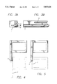
- FIGS. 1 to 6 The invention is explained below by way of example with reference to FIGS. 1 to 6, in which:
- FIG. 1 shows an end view of the guiding device
- FIG. 2 shows a plan view of the guiding device in two positions of the guide frame
- FIG. 3 shows a cross-section and a side view of the longitudinal guide rail
- FIGS. 4 and 5 show plan views of guiding devices with two different drives
- FIG. 6 shows an end view of a guiding device in a further embodiment.
- the guiding device shown in FIGS. 1 and 2 has a device block having a longitudinal guide rail 1 with a slot 10, in which a guide frame 2 is mounted and can be adjusted by a drive 5.
- the guide frame 2 comprises two longitudinal arms 11 and two transverse arms 12, the longitudinal arm mounted in the longitudinal guide rail 1 being made longer than the other for reasons to be explained in more detail.
- Mounted on the guide frame 2 is a carriage which is mounted displaceably on the transverse arms 12 of the guide frame 2 perpendicularly with respect to the guide slot 10.
- the carriage comprises two longitudinal rails 3, which are connected by transverse saddle brackets 4.
- the transverse saddle brackets 4 have a clamping means for a scanner 7, which comprises two horizontal clamping screws 8 and two vertical clamping screws 9.
- the transverse saddle brackets 4 are able to be arrested by clamping screws (not shown) on the longitudinal rails 3 for adaptation to the dimensions of the scanner 7.
- the longitudinal rails 3 in turn are able to be arrested on the transverse arms 12 of the guide frame 2 by clamping screws (not shown), in order to avoid any displacement of the scanner transversely with respect to the longitudinal slot 10 during the scanning operation.
- the limit switches are expediently arranged adjustably in the longitudinal direction and interact with stops (likewise not shown) on the guide frame 2.
- the limit switches may be mounted adjustably on a rod fastened on the longitudinal guide rail 1 or in a slot 14 of the longitudinal guide rail (FIG. 3).
- the limit switches may be signal switches, which generate visual and/or acoustic signals, upon the triggering of which an operator can actuate the scanning switch 6 of the scanner 7 and thereby begin or end the scanning operation. It is also possible to couple the limit switches, for example mechanically, to the scanning switch 6.
- FIGS. 4 and 5 show two possible ways of driving the guide frame 2.
- the guiding device In the case of a rack-and-pinion drive, in which the drive pinion must be arranged at the lower end of the longitudinal guide rail 1, the guiding device has a greater space requirement in the longitudinal direction, since the longitudinal arm 11 of the guide frame 2, guided in the longitudinal rail 1, must be in engagement with the drive 5 when the frame 2 is in the starting position, as FIG. 4 reveals.
- the space requirement of the guiding device is less, since the corresponding longitudinal arm 11 of the guide frame 2 is in drive connection via the control chain in every position.
- FIG. 6 shows an embodiment in which the complete device block is pivotally arranged on a base plate 13.
- the device block is brought into the pivoted position diagrammatically shown.
Landscapes
- Engineering & Computer Science (AREA)
- Theoretical Computer Science (AREA)
- Physics & Mathematics (AREA)
- General Physics & Mathematics (AREA)
- General Engineering & Computer Science (AREA)
- Multimedia (AREA)
- Human Computer Interaction (AREA)
- Facsimile Scanning Arrangements (AREA)
Abstract
The invention relates to a guiding device for hand scanners which makes it possible to use such scanners with straight guidance, with uniform applied pressure, with uniform scanning speed and defined overlapping of scanned columns. For this purpose, the device has a device block, comprising a longitudinal guide rail with a longitudinal guide slot, guided in which is a guide frame, on which a carriage is mounted displaceably perpendicularly with respect to the guide slot and has a clamp or similar device for a scanner, and comprising a drive for adjusting the guide frame.
Description
The invention relates to a guiding device for a hand scanner.
Scanners are used for the direct acquisition of graphics, images, documents etc. in a computer. In the case of most scanners currently available, the image original is illuminated and scanned line by line by light-sensitive elements. In order to obtain a complete image, either the original is taken past the recording elements or the original remains stationary and the recording elements are moved past it. The first type includes draw-in scanners, the second type includes flat-bed scanners and hand scanners.
The advantages of the hand scanner are its small dimensions and, in particular, its low price. Disadvantages occur due to the guidance by hand with regard to straight, rectangular guidance over the page to be scanned, uniform speed, uniform applied pressure and overlapping of about 10 cm when scanning at least two scanned columns.
DE-9105881 discloses a guiding device which has a longitudinal guide rail on which there is displaceably mounted a carriage which has a clamping means for the hand scanner.
U.S. Pat. No. 5,058,188 discloses a guiding device for a hand scanner which has a housing with a rectangular guide opening, in which the hand scanner is displaceably mounted in order to scan both a document and a scale.
The invention is based on the object of providing a guiding device of a simple design which permits the use of conventional hand scanners with regard to straight guidance, uniform applied pressure, uniform speed and overlapping.
This object is achieved according to the invention by the features specified in the defining part of claim 1. Expedient developments of the invention emerge from the subclaims.
The proposed design makes it possible to clamp hand scanners of conventional dimensions firmly in the guiding device and to carry out the scanning operation without any problems.
The invention is explained below by way of example with reference to FIGS. 1 to 6, in which:
FIG. 1 shows an end view of the guiding device,
FIG. 2 shows a plan view of the guiding device in two positions of the guide frame,
FIG. 3 shows a cross-section and a side view of the longitudinal guide rail,
FIGS. 4 and 5 show plan views of guiding devices with two different drives, and
FIG. 6 shows an end view of a guiding device in a further embodiment.
The guiding device shown in FIGS. 1 and 2 has a device block having a longitudinal guide rail 1 with a slot 10, in which a guide frame 2 is mounted and can be adjusted by a drive 5. The guide frame 2 comprises two longitudinal arms 11 and two transverse arms 12, the longitudinal arm mounted in the longitudinal guide rail 1 being made longer than the other for reasons to be explained in more detail. Mounted on the guide frame 2 is a carriage which is mounted displaceably on the transverse arms 12 of the guide frame 2 perpendicularly with respect to the guide slot 10.
The carriage comprises two longitudinal rails 3, which are connected by transverse saddle brackets 4. The transverse saddle brackets 4 have a clamping means for a scanner 7, which comprises two horizontal clamping screws 8 and two vertical clamping screws 9. The transverse saddle brackets 4 are able to be arrested by clamping screws (not shown) on the longitudinal rails 3 for adaptation to the dimensions of the scanner 7. The longitudinal rails 3 in turn are able to be arrested on the transverse arms 12 of the guide frame 2 by clamping screws (not shown), in order to avoid any displacement of the scanner transversely with respect to the longitudinal slot 10 during the scanning operation.
Arranged on the longitudinal guide rail 1 are two limit switches (not shown), by means of which the operation of the scanner 7, ie. switching it on and off, can be controlled. The limit switches are expediently arranged adjustably in the longitudinal direction and interact with stops (likewise not shown) on the guide frame 2. The limit switches may be mounted adjustably on a rod fastened on the longitudinal guide rail 1 or in a slot 14 of the longitudinal guide rail (FIG. 3).
The limit switches may be signal switches, which generate visual and/or acoustic signals, upon the triggering of which an operator can actuate the scanning switch 6 of the scanner 7 and thereby begin or end the scanning operation. It is also possible to couple the limit switches, for example mechanically, to the scanning switch 6.
FIGS. 4 and 5 show two possible ways of driving the guide frame 2. In the case of a rack-and-pinion drive, in which the drive pinion must be arranged at the lower end of the longitudinal guide rail 1, the guiding device has a greater space requirement in the longitudinal direction, since the longitudinal arm 11 of the guide frame 2, guided in the longitudinal rail 1, must be in engagement with the drive 5 when the frame 2 is in the starting position, as FIG. 4 reveals. In the case of a control-chain drive, the space requirement of the guiding device is less, since the corresponding longitudinal arm 11 of the guide frame 2 is in drive connection via the control chain in every position.
FIG. 6 shows an embodiment in which the complete device block is pivotally arranged on a base plate 13. For loading an original to be scanned, the device block is brought into the pivoted position diagrammatically shown.
Claims (6)
1. A guiding device for a hand scanner, comprising a longitudinal guide rail with a guide slot in which is guided a guide frame including two longitudinal arms and two transverse arms, on which a carriage having clamping means for a hand scanner, two longitudinal rails which can be arrested on the guide frame by clamping means and two transverse saddle brackets mounted in such a way that they can be displaced and arrested by clamping means on the longitudinal rails is mounted in such a way that it can be displaced and arrested perpendicularly with respect to the guide slot, and a drive for adjusting the guide frame.
2. The guiding device as claimed in claim 1, wherein the transverse saddle brackets have horizontal and vertical clamping screws for firmly clamping the scanner.
3. The guiding device as claimed in claim 1, which comprises a rack-and-pinion drive for driving the guide frame.
4. The guiding device as claimed in claim 1, which comprises a control-chain drive for driving the guide frame.
5. The guiding device as claimed in claim 1, further comprising a base plate, on which the guide rail is pivotally mounted.
6. Apparatus for scanning an image, comprising:
scanning means; and
a guiding device for the scanning means, comprising a longitudinal guide rail with a guide slot in which is guided a guide frame including two longitudinal arms and two transverse arms, on which a carriage having clamping means for the scanning means, two longitudinal rails which can be arrested on the guide frame by clamping means and two transverse saddle brackets mounted in such a way that they can be displaced and arrested by clamping means on the longitudinal rails is mounted in such a way that it can be displaced and arrested perpendicularly with respect to the guide slot, and a drive for adjusting the guide frame.
Applications Claiming Priority (2)
| Application Number | Priority Date | Filing Date | Title |
|---|---|---|---|
| DE4206275.6 | 1992-02-28 | ||
| DE4206275A DE4206275C1 (en) | 1992-02-28 | 1992-02-28 | Guiding equipment for hand scanner to provide even application pressure in straight line - has guide rail with slot for receiving carriage contg. clamping screws for fixing scanner to carriage |
Publications (1)
| Publication Number | Publication Date |
|---|---|
| US5435426A true US5435426A (en) | 1995-07-25 |
Family
ID=6452867
Family Applications (1)
| Application Number | Title | Priority Date | Filing Date |
|---|---|---|---|
| US08/022,704 Expired - Fee Related US5435426A (en) | 1992-02-28 | 1993-03-01 | Guiding device for a hand scanner |
Country Status (2)
| Country | Link |
|---|---|
| US (1) | US5435426A (en) |
| DE (1) | DE4206275C1 (en) |
Citations (16)
| Publication number | Priority date | Publication date | Assignee | Title |
|---|---|---|---|---|
| JPS5525151A (en) * | 1978-08-10 | 1980-02-22 | Nec Corp | Character reader |
| DE3006579A1 (en) * | 1980-02-21 | 1981-08-27 | Computer Gesellschaft Konstanz Mbh, 7750 Konstanz | Hand-held data reader - has optional mechanical guidance system with clamp movable in carrier bridging guide track |
| JPS5737972A (en) * | 1980-08-13 | 1982-03-02 | Ricoh Co Ltd | Manually operated subscanning type reader |
| EP0142967A2 (en) * | 1983-11-23 | 1985-05-29 | Unisplay S.A. | Optical document scanner |
| US4553035A (en) * | 1983-08-30 | 1985-11-12 | Mylex Corporation | Data acquisition control method and system for a hand held reader |
| US4684998A (en) * | 1983-06-15 | 1987-08-04 | Canon Kabushiki Kaisha | Image reader suitable for manual scanning |
| US4721859A (en) * | 1981-03-25 | 1988-01-26 | John Lewis | Processing of optical information by indexing with a graticule scale |
| US4758732A (en) * | 1987-04-02 | 1988-07-19 | Kyriakides Anastasios N | Data sheet support with scanner guide and manual feed |
| US4831459A (en) * | 1987-02-06 | 1989-05-16 | Alps Electric Co., Ltd. | Guide apparatus with rotating elements for ensuring perpendicular scanning movements of a hand-operated image scanner |
| US4860377A (en) * | 1984-10-30 | 1989-08-22 | Kabushiki Kaisha Toshiba | Hand scanner input system and a sheet used in hand scanner input system |
| US4959871A (en) * | 1983-09-28 | 1990-09-25 | Kabushiki Kaisha Toshiba | Image input/output apparatus |
| US4996775A (en) * | 1989-11-06 | 1991-03-05 | William Sass | Image reader guide |
| DE9105881U1 (en) * | 1991-05-11 | 1991-08-29 | Kolberg, Hans, 2000 Hamburg | Parallel guidance aid for handheld scanners |
| US5058188A (en) * | 1989-11-10 | 1991-10-15 | Kabushiki Kaisha | Manual scan type image reader for correcting read image data to faithfully reproduce read image |
| US5239759A (en) * | 1989-04-28 | 1993-08-31 | Dudek Raymond A | Image scanner guide |
| US5254860A (en) * | 1992-07-24 | 1993-10-19 | Industrial Technology Research Institute | Apparatus for guiding an optical character reader over an information containing card |
-
1992
- 1992-02-28 DE DE4206275A patent/DE4206275C1/en not_active Expired - Fee Related
-
1993
- 1993-03-01 US US08/022,704 patent/US5435426A/en not_active Expired - Fee Related
Patent Citations (16)
| Publication number | Priority date | Publication date | Assignee | Title |
|---|---|---|---|---|
| JPS5525151A (en) * | 1978-08-10 | 1980-02-22 | Nec Corp | Character reader |
| DE3006579A1 (en) * | 1980-02-21 | 1981-08-27 | Computer Gesellschaft Konstanz Mbh, 7750 Konstanz | Hand-held data reader - has optional mechanical guidance system with clamp movable in carrier bridging guide track |
| JPS5737972A (en) * | 1980-08-13 | 1982-03-02 | Ricoh Co Ltd | Manually operated subscanning type reader |
| US4721859A (en) * | 1981-03-25 | 1988-01-26 | John Lewis | Processing of optical information by indexing with a graticule scale |
| US4684998A (en) * | 1983-06-15 | 1987-08-04 | Canon Kabushiki Kaisha | Image reader suitable for manual scanning |
| US4553035A (en) * | 1983-08-30 | 1985-11-12 | Mylex Corporation | Data acquisition control method and system for a hand held reader |
| US4959871A (en) * | 1983-09-28 | 1990-09-25 | Kabushiki Kaisha Toshiba | Image input/output apparatus |
| EP0142967A2 (en) * | 1983-11-23 | 1985-05-29 | Unisplay S.A. | Optical document scanner |
| US4860377A (en) * | 1984-10-30 | 1989-08-22 | Kabushiki Kaisha Toshiba | Hand scanner input system and a sheet used in hand scanner input system |
| US4831459A (en) * | 1987-02-06 | 1989-05-16 | Alps Electric Co., Ltd. | Guide apparatus with rotating elements for ensuring perpendicular scanning movements of a hand-operated image scanner |
| US4758732A (en) * | 1987-04-02 | 1988-07-19 | Kyriakides Anastasios N | Data sheet support with scanner guide and manual feed |
| US5239759A (en) * | 1989-04-28 | 1993-08-31 | Dudek Raymond A | Image scanner guide |
| US4996775A (en) * | 1989-11-06 | 1991-03-05 | William Sass | Image reader guide |
| US5058188A (en) * | 1989-11-10 | 1991-10-15 | Kabushiki Kaisha | Manual scan type image reader for correcting read image data to faithfully reproduce read image |
| DE9105881U1 (en) * | 1991-05-11 | 1991-08-29 | Kolberg, Hans, 2000 Hamburg | Parallel guidance aid for handheld scanners |
| US5254860A (en) * | 1992-07-24 | 1993-10-19 | Industrial Technology Research Institute | Apparatus for guiding an optical character reader over an information containing card |
Also Published As
| Publication number | Publication date |
|---|---|
| DE4206275C1 (en) | 1993-05-27 |
Similar Documents
| Publication | Publication Date | Title |
|---|---|---|
| DE69025796T2 (en) | Device and method for image scanning | |
| US4839741A (en) | Image reproducing apparatus with CCD scanner and bubble jet printer simultaneously driven by a common belt in opposite directions and operated asynchronously | |
| US4567528A (en) | Document scanners | |
| CA2061878A1 (en) | Information processing apparatus | |
| EP0168256A3 (en) | Hand scanner | |
| EP0115366B2 (en) | Device for optically scanning a document | |
| JPH0215150B2 (en) | ||
| US5435426A (en) | Guiding device for a hand scanner | |
| DE3887278T2 (en) | OPTICAL SCAN SYSTEM WITH ROTATING PLATE MOUNTING AND METHOD FOR CHARGING THEREOF. | |
| CA1169957A (en) | Arrangement for scanning originals provided with graphic patterns | |
| CA2075030A1 (en) | Self adjusting scanner apparatus | |
| EP0182398B1 (en) | Document scanning method and apparatus | |
| JP2902655B2 (en) | Image reading apparatus and image reading method | |
| US20060033964A1 (en) | Adjustable bounding box for transparent scanner | |
| US4716300A (en) | Apparatus for scanning documents in a raster line mode using margin stops | |
| US5645335A (en) | Device for converting the pictures displayed on a luminous surface into electrical signals | |
| CA1059635A (en) | Apparatus for scanning a selected face portion of a graphic record | |
| WO1989010036A1 (en) | Scanner for scanning an original document | |
| JPS62115592A (en) | Apparatus for making action surface of work head passing trough slot in document orbit wall flush with internal surface of said wall | |
| JPH01158872A (en) | Optical image reading device | |
| JP3001581B2 (en) | Image reading device | |
| EP0428371A3 (en) | Scanning carriage motion control in an image input device | |
| JPS613558A (en) | Information reader | |
| JPH02184166A (en) | Reader | |
| JP3733718B2 (en) | Image reading device |
Legal Events
| Date | Code | Title | Description |
|---|---|---|---|
| REMI | Maintenance fee reminder mailed | ||
| LAPS | Lapse for failure to pay maintenance fees | ||
| FP | Lapsed due to failure to pay maintenance fee |
Effective date: 19990725 |
|
| STCH | Information on status: patent discontinuation |
Free format text: PATENT EXPIRED DUE TO NONPAYMENT OF MAINTENANCE FEES UNDER 37 CFR 1.362 |