US5406829A - Temperature control for chemical sensors - Google Patents
Temperature control for chemical sensors Download PDFInfo
- Publication number
- US5406829A US5406829A US08/229,899 US22989994A US5406829A US 5406829 A US5406829 A US 5406829A US 22989994 A US22989994 A US 22989994A US 5406829 A US5406829 A US 5406829A
- Authority
- US
- United States
- Prior art keywords
- frequency
- sensor
- temperature
- sensors
- chemical
- Prior art date
- Legal status (The legal status is an assumption and is not a legal conclusion. Google has not performed a legal analysis and makes no representation as to the accuracy of the status listed.)
- Expired - Lifetime
Links
- 239000000126 substance Substances 0.000 claims abstract description 21
- 238000010438 heat treatment Methods 0.000 claims abstract description 6
- 239000012530 fluid Substances 0.000 claims description 8
- 239000012491 analyte Substances 0.000 claims description 7
- 238000012544 monitoring process Methods 0.000 description 3
- 239000000758 substrate Substances 0.000 description 2
- 238000010521 absorption reaction Methods 0.000 description 1
- 238000005259 measurement Methods 0.000 description 1
- 238000000034 method Methods 0.000 description 1
- 239000010409 thin film Substances 0.000 description 1
Images
Classifications
-
- G—PHYSICS
- G05—CONTROLLING; REGULATING
- G05D—SYSTEMS FOR CONTROLLING OR REGULATING NON-ELECTRIC VARIABLES
- G05D23/00—Control of temperature
- G05D23/19—Control of temperature characterised by the use of electric means
- G05D23/20—Control of temperature characterised by the use of electric means with sensing elements having variation of electric or magnetic properties with change of temperature
-
- G—PHYSICS
- G05—CONTROLLING; REGULATING
- G05D—SYSTEMS FOR CONTROLLING OR REGULATING NON-ELECTRIC VARIABLES
- G05D23/00—Control of temperature
- G05D23/19—Control of temperature characterised by the use of electric means
- G05D23/1927—Control of temperature characterised by the use of electric means using a plurality of sensors
- G05D23/1928—Control of temperature characterised by the use of electric means using a plurality of sensors sensing the temperature of one space
Definitions
- the present invention relates to chemical sensors, and more particularly to temperature control for chemical sensors to more closely maintain the temperature of the sensors at a desired steady state value.
- Acoustic wave chemical sensors detect the presence of an analyte chemical by a change in the acoustic properties, such as resonant frequency, caused by absorption of the analyte chemical by a thin film coated on a piezoelectric device. These sensors are very temperature sensitive, and systems incorporating them need to provide means for controlling the device temperature.
- a common sensor package such as that disclosed in NASA Tech Briefs, April 1993, encloses two sensors within a metallic case incorporating a temperature sensor, one chemical sensor being a reference sensor that is isolated from a fluid being measured and the other being a test sensor across which the fluid flows. The frequency outputs of the two chemical sensors are mixed together to produce a difference frequency.
- the difference frequency is a measure of the analyte chemical in the fluid flowing across the test sensor.
- the case is heated by a heating element controlled by a feedback loop from the temperature sensor, which maintains a constant case temperature.
- the temperature of the test sensor is not necessarily equal to the temperature of the case.
- the acoustic nature of the chemical sensor makes direct attachment of the temperature sensor to the chemical sensor difficult.
- the present invention provides temperature control for an acoustic wave chemical sensor by monitoring the frequency of a reference sensor in the same case with a test sensor.
- the changes in frequency of the reference sensor reflect changes due to temperature.
- a frequency counter/discriminator converts the frequency variations into an error signal that is fed back to a heating element that heats the case.
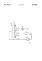
- the FIGURE is a block diagrammatic view of a temperature control system for acoustic wave chemical sensors according to the present invention.
- a pair of chemical sensors 12, 14 are located within a common heat conductive case or on a common supporting substrate 10.
- One of the sensors is a test sensor 12 that is exposed to a fluid that has an analyte chemical to be measured.
- the other sensor is a reference sensor 14 that is not exposed to the fluid.
- An electrical signal from each sensor 12, 14, representing the resonant frequency f T , f R of each sensor, is input to a mixer 16 that provides an output frequency f D which is the difference in frequency between the test and reference sensor resonant frequencies.
- This is a conventional measurement scheme using a two sensor package.
- the case 10 has a heating element 18 attached to it which is controlled by a heater control signal H c .
- the heater control signal H c is generated by a feedback loop 20 that includes a frequency counter/discriminator 22 and a feedback loop amplifier/filter 24.
- the frequency signal f R from the reference sensor 14 is input to the frequency counter/discriminator 22 to produce an error signal E that is a measure of the offset in frequency between f R and a constant baseline frequency f B .
- the error signal E is input to the amplifier/filter 24 to produce the heater control signal H c . Since the resonant frequency f R of the reference sensor 14 is a function of its temperature, by monitoring the frequency output of the reference sensor 14 the case or substrate 10 is maintained at a temperature by the heating element 18 that keeps the temperature of the sensors 12, 14 at the desired steady state temperature without the need of an additional temperature sensor.
- the present invention provides temperature control for chemical sensors by monitoring the frequency of a reference sensor packaged with a test sensor within a heated case, providing a heater control signal as a function of the frequency to maintain the temperature of the sensors at a desired steady state value.
Landscapes
- Physics & Mathematics (AREA)
- General Physics & Mathematics (AREA)
- Engineering & Computer Science (AREA)
- Automation & Control Theory (AREA)
- Investigating Or Analyzing Materials By The Use Of Ultrasonic Waves (AREA)
- Control Of Temperature (AREA)
Abstract
Description
Claims (2)
Priority Applications (3)
| Application Number | Priority Date | Filing Date | Title |
|---|---|---|---|
| US08/229,899 US5406829A (en) | 1994-04-19 | 1994-04-19 | Temperature control for chemical sensors |
| EP95302269A EP0678799A3 (en) | 1994-04-19 | 1995-04-05 | Temperature control for chemical sensors. |
| JP7116547A JP2688575B2 (en) | 1994-04-19 | 1995-04-18 | Chemical sensor |
Applications Claiming Priority (1)
| Application Number | Priority Date | Filing Date | Title |
|---|---|---|---|
| US08/229,899 US5406829A (en) | 1994-04-19 | 1994-04-19 | Temperature control for chemical sensors |
Publications (1)
| Publication Number | Publication Date |
|---|---|
| US5406829A true US5406829A (en) | 1995-04-18 |
Family
ID=22863121
Family Applications (1)
| Application Number | Title | Priority Date | Filing Date |
|---|---|---|---|
| US08/229,899 Expired - Lifetime US5406829A (en) | 1994-04-19 | 1994-04-19 | Temperature control for chemical sensors |
Country Status (3)
| Country | Link |
|---|---|
| US (1) | US5406829A (en) |
| EP (1) | EP0678799A3 (en) |
| JP (1) | JP2688575B2 (en) |
Cited By (9)
| Publication number | Priority date | Publication date | Assignee | Title |
|---|---|---|---|---|
| US5936150A (en) * | 1998-04-13 | 1999-08-10 | Rockwell Science Center, Llc | Thin film resonant chemical sensor with resonant acoustic isolator |
| US6134944A (en) * | 1999-04-29 | 2000-10-24 | The Regents Of The University Of California | System and method for preconcentrating, identifying, and quantifying chemical and biological substances |
| US6321588B1 (en) * | 1998-09-11 | 2001-11-27 | Femtometrics, Inc. | Chemical sensor array |
| US20050033819A1 (en) * | 2003-08-05 | 2005-02-10 | Richard Gambino | System and method for manufacturing wireless devices |
| US6975944B1 (en) * | 1999-09-28 | 2005-12-13 | Alpha Mos | Method and apparatus for monitoring materials used in electronics |
| WO2004044672A3 (en) * | 2002-08-05 | 2009-07-16 | Univ New York State Res Found | System and method for manufacturing wireless devices |
| US7696763B1 (en) * | 2002-09-09 | 2010-04-13 | Yizhong Sun | Sensor and method for detecting analytes in fluids |
| CN105466495A (en) * | 2015-12-31 | 2016-04-06 | 中国空气动力研究与发展中心计算空气动力研究所 | Method for measuring nonuniform temperature field in wall and wall thickness |
| US10605778B2 (en) * | 2017-09-01 | 2020-03-31 | Matrix Sensors, Inc. | Gas sensor incorporating a temperature-controlled sensing material |
Families Citing this family (4)
| Publication number | Priority date | Publication date | Assignee | Title |
|---|---|---|---|---|
| JP2006300742A (en) * | 2005-04-21 | 2006-11-02 | Shizuoka Prefecture | Chemical substance detection device using oscillation frequency adjusting system |
| CN104596667B (en) * | 2015-01-05 | 2017-12-01 | 中国空气动力研究与发展中心计算空气动力研究所 | The sensitivity method of ultrasonic listening interior of articles transient state non-uniform temperature field |
| CN104571202B (en) * | 2015-01-05 | 2017-11-03 | 杭州电子科技大学 | A kind of temperature acquisition control system and control method based on ARM |
| CN104792435B (en) * | 2015-04-21 | 2018-02-13 | 中国空气动力研究与发展中心计算空气动力研究所 | The method for reconstructing of inside configuration non-uniform temperature field based on transient state thermal boundary inverting |
Citations (19)
| Publication number | Priority date | Publication date | Assignee | Title |
|---|---|---|---|---|
| US3164004A (en) * | 1961-05-15 | 1965-01-05 | Exxon Research Engineering Co | Coated piezoelectric analyzers |
| US3756068A (en) * | 1971-04-30 | 1973-09-04 | Us Army | Carbon dioxide concentration sensor |
| US3848457A (en) * | 1973-05-14 | 1974-11-19 | Minnesota Mining & Mfg | Gaseous fluid monitoring apparatus |
| US3879992A (en) * | 1970-05-12 | 1975-04-29 | California Inst Of Techn | Multiple crystal oscillator measuring apparatus |
| US3895912A (en) * | 1974-11-06 | 1975-07-22 | Nasa | Carbon monoxide monitor |
| US4258563A (en) * | 1977-12-16 | 1981-03-31 | Nippon Soken, Inc. | Gas sensor |
| US4312228A (en) * | 1979-07-30 | 1982-01-26 | Henry Wohltjen | Methods of detection with surface acoustic wave and apparati therefor |
| US4399686A (en) * | 1980-02-21 | 1983-08-23 | Engstrom Medical Ab | Gas detector |
| US4498330A (en) * | 1981-05-15 | 1985-02-12 | U.S. Industrial Products Co. | Gas detecting and monitoring device |
| US4503703A (en) * | 1982-09-10 | 1985-03-12 | Pagel Hayes L | Molecular gas detector and analyzer |
| US4533520A (en) * | 1984-07-02 | 1985-08-06 | Mine Safety Appliances Company | Circuit for constant temperature operation of a catalytic combustible gas detector |
| US4730478A (en) * | 1985-06-18 | 1988-03-15 | Icor Ab | Gas analyzer |
| US4759210A (en) * | 1986-06-06 | 1988-07-26 | Microsensor Systems, Inc. | Apparatus for gas-monitoring and method of conducting same |
| US4860573A (en) * | 1985-10-03 | 1989-08-29 | Nederlandes Organisatie Voor Toegepast-Natuurwetenschappelijk Onderzoek Tno | Composite substrate, intended for an apparatus for quantitative detection of a component present in a gas or liquid |
| US5012668A (en) * | 1989-08-22 | 1991-05-07 | The Boeing Company | Inclined electrode surface acoustic wave substance sensor |
| US5042288A (en) * | 1990-05-25 | 1991-08-27 | The United States Of America As Represented By The Secretary Of The Army | Method of sensing contamination in the atmosphere |
| US5149197A (en) * | 1990-06-12 | 1992-09-22 | Northern Telecom Limited | Piezo electric resonator temperature sensor |
| US5289715A (en) * | 1991-11-12 | 1994-03-01 | Amerasia Technology Inc. | Vapor detection apparatus and method using an acoustic interferometer |
| US5323636A (en) * | 1993-06-11 | 1994-06-28 | The United States Of America As Represented By The Secretary Of The Army | Dual-channel flexural acoustic wave chemical sensor |
-
1994
- 1994-04-19 US US08/229,899 patent/US5406829A/en not_active Expired - Lifetime
-
1995
- 1995-04-05 EP EP95302269A patent/EP0678799A3/en not_active Withdrawn
- 1995-04-18 JP JP7116547A patent/JP2688575B2/en not_active Expired - Fee Related
Patent Citations (19)
| Publication number | Priority date | Publication date | Assignee | Title |
|---|---|---|---|---|
| US3164004A (en) * | 1961-05-15 | 1965-01-05 | Exxon Research Engineering Co | Coated piezoelectric analyzers |
| US3879992A (en) * | 1970-05-12 | 1975-04-29 | California Inst Of Techn | Multiple crystal oscillator measuring apparatus |
| US3756068A (en) * | 1971-04-30 | 1973-09-04 | Us Army | Carbon dioxide concentration sensor |
| US3848457A (en) * | 1973-05-14 | 1974-11-19 | Minnesota Mining & Mfg | Gaseous fluid monitoring apparatus |
| US3895912A (en) * | 1974-11-06 | 1975-07-22 | Nasa | Carbon monoxide monitor |
| US4258563A (en) * | 1977-12-16 | 1981-03-31 | Nippon Soken, Inc. | Gas sensor |
| US4312228A (en) * | 1979-07-30 | 1982-01-26 | Henry Wohltjen | Methods of detection with surface acoustic wave and apparati therefor |
| US4399686A (en) * | 1980-02-21 | 1983-08-23 | Engstrom Medical Ab | Gas detector |
| US4498330A (en) * | 1981-05-15 | 1985-02-12 | U.S. Industrial Products Co. | Gas detecting and monitoring device |
| US4503703A (en) * | 1982-09-10 | 1985-03-12 | Pagel Hayes L | Molecular gas detector and analyzer |
| US4533520A (en) * | 1984-07-02 | 1985-08-06 | Mine Safety Appliances Company | Circuit for constant temperature operation of a catalytic combustible gas detector |
| US4730478A (en) * | 1985-06-18 | 1988-03-15 | Icor Ab | Gas analyzer |
| US4860573A (en) * | 1985-10-03 | 1989-08-29 | Nederlandes Organisatie Voor Toegepast-Natuurwetenschappelijk Onderzoek Tno | Composite substrate, intended for an apparatus for quantitative detection of a component present in a gas or liquid |
| US4759210A (en) * | 1986-06-06 | 1988-07-26 | Microsensor Systems, Inc. | Apparatus for gas-monitoring and method of conducting same |
| US5012668A (en) * | 1989-08-22 | 1991-05-07 | The Boeing Company | Inclined electrode surface acoustic wave substance sensor |
| US5042288A (en) * | 1990-05-25 | 1991-08-27 | The United States Of America As Represented By The Secretary Of The Army | Method of sensing contamination in the atmosphere |
| US5149197A (en) * | 1990-06-12 | 1992-09-22 | Northern Telecom Limited | Piezo electric resonator temperature sensor |
| US5289715A (en) * | 1991-11-12 | 1994-03-01 | Amerasia Technology Inc. | Vapor detection apparatus and method using an acoustic interferometer |
| US5323636A (en) * | 1993-06-11 | 1994-06-28 | The United States Of America As Represented By The Secretary Of The Army | Dual-channel flexural acoustic wave chemical sensor |
Non-Patent Citations (2)
| Title |
|---|
| "Surface-Acoustic-Wave Piezoelectric Microbalance" Langley Research Center, Hampton, Vir. |
| Surface Acoustic Wave Piezoelectric Microbalance Langley Research Center, Hampton, Vir. * |
Cited By (11)
| Publication number | Priority date | Publication date | Assignee | Title |
|---|---|---|---|---|
| US5936150A (en) * | 1998-04-13 | 1999-08-10 | Rockwell Science Center, Llc | Thin film resonant chemical sensor with resonant acoustic isolator |
| US6321588B1 (en) * | 1998-09-11 | 2001-11-27 | Femtometrics, Inc. | Chemical sensor array |
| US6134944A (en) * | 1999-04-29 | 2000-10-24 | The Regents Of The University Of California | System and method for preconcentrating, identifying, and quantifying chemical and biological substances |
| US6975944B1 (en) * | 1999-09-28 | 2005-12-13 | Alpha Mos | Method and apparatus for monitoring materials used in electronics |
| WO2004044672A3 (en) * | 2002-08-05 | 2009-07-16 | Univ New York State Res Found | System and method for manufacturing wireless devices |
| US7696763B1 (en) * | 2002-09-09 | 2010-04-13 | Yizhong Sun | Sensor and method for detecting analytes in fluids |
| US20050033819A1 (en) * | 2003-08-05 | 2005-02-10 | Richard Gambino | System and method for manufacturing wireless devices |
| US7477050B2 (en) * | 2003-08-05 | 2009-01-13 | Research Foundation Of The State University Of New York | Magnetic sensor having a coil around a permeable magnetic core |
| CN105466495A (en) * | 2015-12-31 | 2016-04-06 | 中国空气动力研究与发展中心计算空气动力研究所 | Method for measuring nonuniform temperature field in wall and wall thickness |
| CN105466495B (en) * | 2015-12-31 | 2018-04-10 | 中国空气动力研究与发展中心计算空气动力研究所 | Measuring method that is a kind of while obtaining pars intramuralis non-uniform temperature field and wall thickness |
| US10605778B2 (en) * | 2017-09-01 | 2020-03-31 | Matrix Sensors, Inc. | Gas sensor incorporating a temperature-controlled sensing material |
Also Published As
| Publication number | Publication date |
|---|---|
| JP2688575B2 (en) | 1997-12-10 |
| EP0678799A2 (en) | 1995-10-25 |
| EP0678799A3 (en) | 1996-04-17 |
| JPH07294496A (en) | 1995-11-10 |
Similar Documents
| Publication | Publication Date | Title |
|---|---|---|
| US5406829A (en) | Temperature control for chemical sensors | |
| US5515714A (en) | Vapor composition and flow sensor | |
| JP3229168B2 (en) | Flow detector | |
| EP0173461B1 (en) | Thermal diffusion fluid flow sensor | |
| US8561461B2 (en) | Calorimetric flow meter having high heat conductivity strips | |
| EP2230491B1 (en) | Method of calibrating a thermal mass flowmeter | |
| JP2002500346A (en) | Self-oscillating fluid sensor | |
| US4592665A (en) | Temperature-controlled systems for non-thermal parameter measurements | |
| US5189362A (en) | High frequency signal measurement circuits utilizing temperature-sensitive devices | |
| US7823444B2 (en) | Device and process for measuring the velocity of flow of a fluid using pulse signal generated based on feedback | |
| EP0849594A2 (en) | Method of operating a calorimetric gas sensor | |
| JPH04230806A (en) | Flow rate sensor | |
| US6340816B1 (en) | Pyroelectric detector with feedback amplifier for enhanced low frequency response | |
| JPH01313728A (en) | Crystal vacuum gauge | |
| GB2297164A (en) | Arrangement for measuring the through-flow in a fluid channel | |
| JPS5872180A (en) | Thermal contact fixing device | |
| US6086251A (en) | Process for operating a thermocouple to measure velocity or thermal conductivity of a gas | |
| DE3474359D1 (en) | Measuring device for physical properties of fluids | |
| RU2018090C1 (en) | Mass flowmeter | |
| WO1991002243A1 (en) | A method and a monitor for detecting combustible gases | |
| JPH02248817A (en) | Differential pressure type flow rate control apparatus | |
| JPH0341351A (en) | Heat conduction type measuring apparatus | |
| SU767525A1 (en) | Thermal flow meter | |
| KR0163621B1 (en) | Temperature and speed measuring method in moving field using one thermal line sensor | |
| JPS5839363Y2 (en) | Contamination measuring device |
Legal Events
| Date | Code | Title | Description |
|---|---|---|---|
| AS | Assignment |
Owner name: TEKTRONIX, INC., OREGON Free format text: ASSIGNMENT OF ASSIGNORS INTEREST;ASSIGNORS:RAVEL, MIHIR K.;PEPPER, STEVEN H.;REEL/FRAME:007323/0710 Effective date: 19940412 |
|
| STCF | Information on status: patent grant |
Free format text: PATENTED CASE |
|
| AS | Assignment |
Owner name: ST. CLAIR INTELLECTUAL PROPERTY CONSULTANTS, INC., Free format text: ASSIGNMENT OF ASSIGNORS INTEREST;ASSIGNOR:TEKTRONIX, INC.;REEL/FRAME:008209/0468 Effective date: 19961008 |
|
| FPAY | Fee payment |
Year of fee payment: 4 |
|
| FPAY | Fee payment |
Year of fee payment: 8 |
|
| FPAY | Fee payment |
Year of fee payment: 12 |
|
| FEPP | Fee payment procedure |
Free format text: PAYOR NUMBER ASSIGNED (ORIGINAL EVENT CODE: ASPN); ENTITY STATUS OF PATENT OWNER: LARGE ENTITY |
|
| FEPP | Fee payment procedure |
Free format text: PAYOR NUMBER ASSIGNED (ORIGINAL EVENT CODE: ASPN); ENTITY STATUS OF PATENT OWNER: LARGE ENTITY Free format text: PAYER NUMBER DE-ASSIGNED (ORIGINAL EVENT CODE: RMPN); ENTITY STATUS OF PATENT OWNER: LARGE ENTITY |