US5406408A - Intracavity-doubled tunable optical parametric oscillator - Google Patents
Intracavity-doubled tunable optical parametric oscillator Download PDFInfo
- Publication number
- US5406408A US5406408A US08/212,709 US21270994A US5406408A US 5406408 A US5406408 A US 5406408A US 21270994 A US21270994 A US 21270994A US 5406408 A US5406408 A US 5406408A
- Authority
- US
- United States
- Prior art keywords
- crystal
- cavity
- optical parametric
- parametric oscillator
- harmonic
- Prior art date
- Legal status (The legal status is an assumption and is not a legal conclusion. Google has not performed a legal analysis and makes no representation as to the accuracy of the status listed.)
- Expired - Lifetime
Links
- 230000003287 optical effect Effects 0.000 title claims abstract description 36
- 239000013078 crystal Substances 0.000 claims abstract description 88
- 238000005086 pumping Methods 0.000 claims description 8
- 230000010355 oscillation Effects 0.000 claims description 5
- 229910052594 sapphire Inorganic materials 0.000 description 7
- 239000010980 sapphire Substances 0.000 description 7
- XKRFYHLGVUSROY-UHFFFAOYSA-N Argon Chemical compound [Ar] XKRFYHLGVUSROY-UHFFFAOYSA-N 0.000 description 6
- 238000006243 chemical reaction Methods 0.000 description 6
- 230000008878 coupling Effects 0.000 description 5
- 238000010168 coupling process Methods 0.000 description 5
- 238000005859 coupling reaction Methods 0.000 description 5
- 238000013461 design Methods 0.000 description 4
- 239000006185 dispersion Substances 0.000 description 4
- 229910052786 argon Inorganic materials 0.000 description 3
- 230000005540 biological transmission Effects 0.000 description 3
- 238000011161 development Methods 0.000 description 2
- 238000007493 shaping process Methods 0.000 description 2
- 230000002411 adverse Effects 0.000 description 1
- XBJJRSFLZVLCSE-UHFFFAOYSA-N barium(2+);diborate Chemical compound [Ba+2].[Ba+2].[Ba+2].[O-]B([O-])[O-].[O-]B([O-])[O-] XBJJRSFLZVLCSE-UHFFFAOYSA-N 0.000 description 1
- 238000000576 coating method Methods 0.000 description 1
- 239000002178 crystalline material Substances 0.000 description 1
- 230000009977 dual effect Effects 0.000 description 1
- 230000000694 effects Effects 0.000 description 1
- 238000003780 insertion Methods 0.000 description 1
- 230000037431 insertion Effects 0.000 description 1
- 239000000543 intermediate Substances 0.000 description 1
- 238000004519 manufacturing process Methods 0.000 description 1
- 238000005259 measurement Methods 0.000 description 1
- 238000012986 modification Methods 0.000 description 1
- 230000004048 modification Effects 0.000 description 1
- 239000004065 semiconductor Substances 0.000 description 1
- 230000003595 spectral effect Effects 0.000 description 1
- 238000001228 spectrum Methods 0.000 description 1
- 239000000126 substance Substances 0.000 description 1
- 238000012360 testing method Methods 0.000 description 1
Images


Classifications
-
- G—PHYSICS
- G02—OPTICS
- G02F—OPTICAL DEVICES OR ARRANGEMENTS FOR THE CONTROL OF LIGHT BY MODIFICATION OF THE OPTICAL PROPERTIES OF THE MEDIA OF THE ELEMENTS INVOLVED THEREIN; NON-LINEAR OPTICS; FREQUENCY-CHANGING OF LIGHT; OPTICAL LOGIC ELEMENTS; OPTICAL ANALOGUE/DIGITAL CONVERTERS
- G02F1/00—Devices or arrangements for the control of the intensity, colour, phase, polarisation or direction of light arriving from an independent light source, e.g. switching, gating or modulating; Non-linear optics
- G02F1/35—Non-linear optics
- G02F1/37—Non-linear optics for second-harmonic generation
-
- G—PHYSICS
- G02—OPTICS
- G02F—OPTICAL DEVICES OR ARRANGEMENTS FOR THE CONTROL OF LIGHT BY MODIFICATION OF THE OPTICAL PROPERTIES OF THE MEDIA OF THE ELEMENTS INVOLVED THEREIN; NON-LINEAR OPTICS; FREQUENCY-CHANGING OF LIGHT; OPTICAL LOGIC ELEMENTS; OPTICAL ANALOGUE/DIGITAL CONVERTERS
- G02F1/00—Devices or arrangements for the control of the intensity, colour, phase, polarisation or direction of light arriving from an independent light source, e.g. switching, gating or modulating; Non-linear optics
- G02F1/35—Non-linear optics
- G02F1/39—Non-linear optics for parametric generation or amplification of light, infrared or ultraviolet waves
-
- G—PHYSICS
- G02—OPTICS
- G02F—OPTICAL DEVICES OR ARRANGEMENTS FOR THE CONTROL OF LIGHT BY MODIFICATION OF THE OPTICAL PROPERTIES OF THE MEDIA OF THE ELEMENTS INVOLVED THEREIN; NON-LINEAR OPTICS; FREQUENCY-CHANGING OF LIGHT; OPTICAL LOGIC ELEMENTS; OPTICAL ANALOGUE/DIGITAL CONVERTERS
- G02F1/00—Devices or arrangements for the control of the intensity, colour, phase, polarisation or direction of light arriving from an independent light source, e.g. switching, gating or modulating; Non-linear optics
- G02F1/35—Non-linear optics
- G02F1/353—Frequency conversion, i.e. wherein a light beam is generated with frequency components different from those of the incident light beams
- G02F1/3542—Multipass arrangements, i.e. arrangements to make light pass multiple times through the same element, e.g. using an enhancement cavity
Definitions
- the present invention relates, in general, to an improved titanium-sapphire (Ti:S) pumped optical parametric oscillator, and more particularly to a high power, high repetition rate, intracavity-doubled optical parametric oscillator capable of producing femtosecond pulses tunable in the visible range.
- Ti:S titanium-sapphire
- Femtosecond lasers which have pulse widths of from 10 -15 to 10 -13 seconds, are also important for studying the dynamics and ultimate limits of high-speed semiconductor electronic and optical devices.
- a Ti:sapphire-pumped, optical parametric oscillator which produces an output beam consisting of stable 81 MHz train of pulses having widths in the range of about 100 fs, with the output beam being tunable in at least the visible range of from about 580 nm to 657 nm, and preferably in the range of about 500 nm to 800 nm, with an average total power generated as high as 240 mW.
- the OPO consists of a first nonlinear crystal such as a 1.5 mm thick KTiPO 4 (KTP) crystal, configured in a ring or linear cavity which is synchronously pumped by a self-mode-locked Ti:sapphire laser operating at an 81 MHz repetition rate with an average power of 2.1 W.
- the pumping laser produces, in one embodiment of the invention, 115 fs pulses at a wavelength of 790 nm which activate the KTP crystal to produce oscillation in the cavity.
- the cavity also incorporates a second nonlinear crystal, such as a beta barium borate ( ⁇ -BaB 2 O.sub. 4) crystal in an additional focus in the cavity, and this second crystal is pumped by the cavity oscillation to produce a second harmonic output signal.
- ⁇ -BaB 2 O.sub. 4 beta barium borate
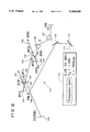
- FIG. 1 is a diagrammatic illustration of a first embodiment of a Ti:sapphire-pumped intracavity-doubled KTP oscillator in a ring configuration
- FIG. 2 is a fast-photodiode oscilloscope trace showing the second harmonic output of the oscillator of FIG. 1 on a 20 ns per division time scale;
- FIG. 3 is a fast-photodiode oscilloscope trace showing the second harmonic output of the oscillator of FIG. 1 on a 2 ns per division time scale;
- FIG. 4 is a real time autocorrelation oscilloscope trace of the second harmonic output of the oscillator of FIG. 1;
- FIG. 5 is a graph illustrating the spectral tuning range of the oscillator of FIG. 1;
- FIG. 6 is a diagrammatic illustration of a second embodiment of a Ti:Sapphire pumped intracavity-doubled KTP oscillator in a linear configuration.
- FIG. 1 in diagrammatic form a ring oscillator 10 which is pumped by a Ti:sapphire laser 12.
- Dispersion compensation is achieved in conventional manner, and the laser 12 produces a pump beam 14 having 115 fs pulses at an 81 MHz repetition rate, with an average output power of 2.1 W at a center wavelength of 790 nm.
- the laser pump beam 14 is directed, as by mirrors 16 and 18 and pump mirror 20, onto a KTiPO 4 crystal 22.
- the OPO 10 includes an output coupler mirror 28, four SF-14 prisms 30, 32, 34 and 36 spaced 20 cm tip-to-tip, a high reflectance mirror 38, and a second pair of focus mirrors 40 and 42 defining the cavity propagation path.
- Mirrors 40 and 42 define a second focus 43 in the ring cavity for a frequency-doubling crystal 44.
- the doubling crystal may be a 47 ⁇ m thick ⁇ -barium borate crystal (BBO) which is Brewster-cut for type I phase matching at a wavelength of 850 nm.
- the pump beam 14 is directed onto the KTP crystal 22, as described above, to produce an output beam wave 50 which is resonated in the ring cavity 10.
- the beam 50 is a selected one of the idler and signal waves generated by the KTP crystal, and preferably is the signal wave.
- the beam travels from mirror 26 to mirror 28, then through the prisms 30, 32, 34 and 36 to mirror 38 which directs the beam into the second focus defined by mirrors 40 and 42. From there, mirror 42 directs the resonating beam back to the KTP crystal.
- mirrors 40 and 42 have a radius equal to 10 cm and all of the mirrors in the ring cavity are coated for a center wavelength of 1.3 ⁇ m.
- the OPO output coupler 28 may provide 1% coupling at 1.3 ⁇ m, or in the alternative may be a high reflecting mirror identical to the other cavity mirrors.
- the BBO crystal 44 is a frequency doubling crystal which responds to the selected signal (or idler) wave 50 to generate a second harmonic signal 52 which passes out of the ring oscillator through mirror 42, as illustrated in FIG. 1.
- This second harmonic signal has a wavelength equal to one half of the wavelength of the selected wave 50, and has a pulse width comparable to that of the laser pump beam 14. This wavelength can be, for example, 500-800 nm, with a pulse width in the femtosecond range.
- Orientation of the BBO crystal for phase matching the second harmonic generation at 1.3 ⁇ m does not significantly increase the reflective loss suffered by the fundamental OPO signal wave 50.
- the unidirectional ring cavity of the present invention gives a single output beam 52 for the second harmonic.
- the cavity Before the device of FIG. 1 can be operated, the cavity must be aligned. Alignment is performed with the additional frequency-doubling focus 43, provided by mirrors 40 and 42, included in the cavity, but without either the BBO crystal 44 or the prism sequence including prisms 30, 32, 34 and 36 inserted. After the oscillator is optimized under these conditions, the prism sequence is inserted, the cavity length is adjusted, and the multipass signal is maximized to regain oscillation. The OPO is again optimized, and the OPO signal beam 50 is used to orient the BBO crystal for phase matching at Brewster's angle. Subsequent insertion of the BBO into the additional focus provided by mirrors 40 and 42 does not destroy the multipass signal through the 1% output coupler 28, and oscillation can easily be regained.
- the ring oscillator 10 When the ring oscillator 10 includes the 1% output coupler 28 and is pumped by a pumping beam at 2.1 W, it produces a signal beam 50 of approximately 80 mW at 1.3 ⁇ m, and 115 mW total second harmonic light in output beam 52.
- the power of the output second harmonic beam 52 through mirror 42 is reduced by Fresnel reflection off the BBO crystal, is reduced by imperfect transmission through the mirror 42, and is reduced by loss from the collimating lens.
- the ring oscillator 10 of the present invention will generate up to 240 mW of second harmonic light at about 115 fs pulse width.
- a 95 fs pulse width has been obtained by using an extracavity two-prism sequence to compress the output pulse, where the two prisms are spaced 17 cm apart to remove any chirp on the pulses.
- the second harmonic pulse train 52 exhibited excellent stability, as illustrated by the oscilloscope traces in FIGS. 2 and 3. Furthermore, as shown in the real time interferometric autocorrelation of FIG. 4, the pulses obtained by this system are clean and quiet.
- the portion 54 of beam 50 which passes through the output coupler 28 typically has pulse widths in the range of 120 to 170 fs, depending upon the intraprism path length.
- the pulse width of the second harmonic output 52 is 115 fs, while a pulse width of 95 fs is measured after the two-prism sequence which reduces the time-bandwidth product from 0.45 to 0.37.
- the time-bandwidth product of the OPO signal fundamental pulses taken through the output coupler is 0.45 (sech 2 fit), suggesting that the OPO fundamental pulse may be slightly chirped.
- the optical parametric oscillator 10 may be tuned by varying the wavelength of the pump 12. However, in the experimental embodiment, the device is angle-tuned by rotating the phase matching angle of the KTP crystal 22 as indicated by arrow 56. Tuning requires slight adjustment of one flat mirror, adjustment of the KTP crystal, and adjustment of the cavity length, with the OPO continuing to oscillate during these adjustments.
- the modified OPO of the present invention which incorporates the intracavity doubling crystal 44, is simplified when using an ultra-thin BBO crystal.
- the type I second harmonic generation tuning curve for BBO is multivalued; that is, a given phase matching angle generally matches 2 distinct wavelengths for second harmonic generation.
- the single-valued point in the second harmonic generation tuning curve which may be referred to as the "degenerate" point, occurs at a wavelength of 1.47 ⁇ m for BBO. At this point, the second harmonic generation group velocity mismatch also goes to zero at the same wavelength.
- the second harmonic generation bandwidth for the 47 ⁇ m thick BBO crystal becomes very large as the sinc 2 ( ⁇ k.l c /2) profiles for the two phase matched wavelengths merge and cross.
- the bandwidth may become as large as about 1700 nm, extending asymmetrically from roughly 1.0 to 2.7 ⁇ m at this point.
- the intracavity circulating power of the fundamental signal was measured at 8 W, yielding a second harmonic generation conversion efficiency of about 1.4%. Based on this measurement, it appears that replacing the output coupler 28 with a high reflector would increase the intracavity circulating power to about 11.5 W and the single harmonic generation conversion efficiency to about 2.1%.
- Use of a slightly thicker doubling crystal 44 will facilitate the production of good power in the second harmonic signal when lower power from pump 12 is used.
- the phase matching bandwidth of even a 300 ⁇ m BBO crystal would permit rotation-free phase matching from about 1.2 ⁇ m to about 1.6 ⁇ m, covering the 600 to 800 nm range in the visible and near-infrared.
- the Brewster-cut BBO crystal 44 minimizes Fresnel loss in the fundamental signal wave 50
- the configuration illustrated in FIG. 1 results in a 21% Fresnel loss at the BBO exit surface for the S-plane-polarized second harmonic beam 52.
- Using a normal-incidence-cut 1.3 ⁇ m antireflection-coated BBO crystal in place of the Brewster-cut crystal 44 would reduce the loss in the second harmonic signal to less than about 6%.
- the only output coupling inefficiency for the second harmonic beam is the transmission through the optical parametric oscillator high reflector mirror 42. In an experimental ring oscillator, the OPO mirrors transmitted about 80% of the second harmonic signal, and specially-designed single-stack mirrors can increase this transmission to about 90%.
- the illustrated configuration with losses of 21% at the BBO exit surface, 20% at the high reflectance oscillator mirror, and 8% at the collimating lens, produces a signal in which about 140 mW of the total 240 mW second harmonic produced by the crystal 44 will be transmitted in beam 52.
- the non-linear loss which may be about 2% of the total loss, due to single harmonic generation in the intracavity-doubled OPO does not play a major role in shaping the OPO fundamental pulse. Pulse broadening due to linear dispersion of such a thin BBO crystal is insubstantial, so it is expected that shorter pump pulses from laser pump source would yield shorter second harmonic generation pulses.
- the intracavity doubling of the present invention achieves approximately an order of magnitude greater power in the second harmonic beam than is possible by extracavity doubling of presently available OPO devices.
- the conversion efficiency is also much greater with an intracavity structure.
- the transverse mode of the OPO is an exceptionally pure, round TEM 00 , which is achievable regardless of the transverse mode of the Ti:sapphire pump laser 12, and apart from slight irregularities due to BBO surface imperfections, this TEM 00 mode is imparted to the frequency-doubled beam 52.
- Intracavity doubling with a thin BBO crystal does not add significantly to the complexity of the oscillator, nor does it reduce its stability.
- the linear loss of the additional focus 43 and the doubling crystal 44 is estimated to be less than about 0.5%, and the tuning range of the oscillator is not adversely affected by the presence of the BBO.
- the use of a reasonably thin BBO crystal permits hands-off phase matching over the tuning range of the oscillator.
- the intracavity frequency-doubled OPO can quite similarly be configured in a linear cavity 110 as shown schematically in FIG. 6.
- the linear cavity frequency-doubled OPO is nearly identical to the ring-cavity embodiment of FIG. 1.
- all cavity design parameters including the radii of curvature of the pump, gain, and doubling mirrors, were identical for the linear and ring cavities.
- Also identical were the KTP crystal cut and orientation, the Ti:sapphire pump laser, the OPO high reflecting mirror coatings, output coupling considerations for the OPO signal beam, and the cut and orientation of the ⁇ -BaB 2 O 4 (BBO) crystal.
- FIG. 6 illustrates a linear optical parametric oscillator 110 which is pumped by a Ti:sapphire laser 112.
- the laser 112 is configured in a standard linear cavity using an 18 mm long titanium-doped (0.1% Ti 3+ by weight) sapphire crystal, and is pumped by an argon laser (not shown), as described above with respect to laser 12.
- the laser 112 produces a pump beam 114 having 115 fs pulses at an 81MHz repetition rate, with an average output power of 2.1 W at a center wavelength of 790 nm.
- the laser pump beam 114 is directed, as by mirrors 116 and 118 and pump mirror 120, onto a KTiOPO 4 crystal 122.
- the OPO 110 includes an output coupler mirror 128, two 60° SF-14 prisms 130 and 132, spaced 20 cm tip-to-tip, and high reflectance mirror 138, and a second pair of focus mirrors 140 and 142 defining the cavity propagation path.
- Mirrors 140 and 142 have radii of 10 cm, for example, and define a second focus 143 in the cavity for a frequency-doubling crystal 144.
- the doubling crystal may be a 47 ⁇ m thick ⁇ -barium borate crystal (BBO) which is Brewster-cut for type I phase matching at a wavelength of 850 nm.
- BBO ⁇ -barium borate crystal
- the pump beam 114 is directed onto the KTP crystal 122, as described above, to produce beam wave 150 which is resonated in the cavity 110.
- the beam 150 is a selected one of the idler and signal waves generated by the KTP crystal, and preferably is the signal wave.
- the beam travels from mirror 126 to mirror 128, then back to 126, through crystal 122 to mirror 124 which directs the beam into the second focus 143 defined by mirror 142, crystal 144, and mirror 140. From there, mirror 140 directs the resonating beam through prisms 130 and 132 to reflecting mirror 138, which returns the beam back through crystal 144 and crystal 122 to mirror 126, which directs the beam to output coupling mirror 128.
- the OPO output coupler 128 may provide 1% coupling at the center wavelength of the OPO, or in the alternative may be a high reflecting mirror identical to mirror 138.
- the linear cavity 110 responds to the selected signal (or idler) wave 150 to generate two second harmonic signals 152 and 153 which pass out of the oscillator in opposite directions through mirrors 140 and 142, respectively, as illustrated in FIG. 6.
- These second harmonic signals have a wavelength equal to one half of the wavelength of the selected wave 150, and each has a pulse width comparable to that of the laser pump beam 114.
- This wavelength can be, for example, 500-800 nm, with a pulse width in the femtosecond range.
- Orientation of the BBO crystal for phase matching the second harmonic generation at 1.3 ⁇ m does not significantly increase the reflective loss suffered by the fundamental OPO signal wave 150.
- the linear cavity frequency-doubled OPO 110 shown in FIG. 6 requires six mirror reflections to make a round trip, while the ring cavity 10 requires 10 mirror reflections for a full round trip.
- the linear cavity design results in two passes through each of the KTP gain and BBO doubling crystals per cavity round trip, while the ring cavity requires only one pass through these crystals per round trip. The number of prism surface reflections is identical for the two cavity designs.
- the linear cavity while simpler to align, results in more linear loss due to reflections than does the ring cavity, and also results in dual SH outputs which may often be seen as a disadvantage since the output power of the second harmonic light is split between two beams and cannot be recombined, as a practical matter.
- a femtosecond pulsed laser such as an argon-pumped mode-locked Ti:sapphire laser is used to pump an intracavity-doubled OPO to generate tunable pulses having widths of about 100 fs.
- the signals are tunable over the range of 580 to 657 nm, in one embodiment of the invention, with a potential tuning range of about 500 to 800 nm.
- the invention provides an important source for high-repetition-rate femtosecond pulses, tunable in the visible range, with high average power, short pulse width, excellent spatial mode quality, high peak power and excellent stability.
- KTP and BBO crystals are described, other nonlinear crystalline materials can be used in the OPO cavity to provide the frequency-doubling described herein.
- the SF-10 prisms used in the Ti:sapphire laser 12 can be replaced with low-dispersion prisms and the pulse shaping parameters of both the pump source and the OPO cavity can be optimized to produce even shorter-pulse operation of the OPO.
Landscapes
- Physics & Mathematics (AREA)
- Nonlinear Science (AREA)
- General Physics & Mathematics (AREA)
- Optics & Photonics (AREA)
- Lasers (AREA)
- Optical Modulation, Optical Deflection, Nonlinear Optics, Optical Demodulation, Optical Logic Elements (AREA)
Abstract
Description
Claims (21)
Priority Applications (1)
| Application Number | Priority Date | Filing Date | Title |
|---|---|---|---|
| US08/212,709 US5406408A (en) | 1993-02-26 | 1994-03-14 | Intracavity-doubled tunable optical parametric oscillator |
Applications Claiming Priority (2)
| Application Number | Priority Date | Filing Date | Title |
|---|---|---|---|
| US07/025,377 US5296960A (en) | 1993-02-26 | 1993-02-26 | Intracavity-doubled tunable optical parametric oscillator |
| US08/212,709 US5406408A (en) | 1993-02-26 | 1994-03-14 | Intracavity-doubled tunable optical parametric oscillator |
Related Parent Applications (1)
| Application Number | Title | Priority Date | Filing Date |
|---|---|---|---|
| US07/025,377 Continuation-In-Part US5296960A (en) | 1993-02-26 | 1993-02-26 | Intracavity-doubled tunable optical parametric oscillator |
Publications (1)
| Publication Number | Publication Date |
|---|---|
| US5406408A true US5406408A (en) | 1995-04-11 |
Family
ID=46248439
Family Applications (1)
| Application Number | Title | Priority Date | Filing Date |
|---|---|---|---|
| US08/212,709 Expired - Lifetime US5406408A (en) | 1993-02-26 | 1994-03-14 | Intracavity-doubled tunable optical parametric oscillator |
Country Status (1)
| Country | Link |
|---|---|
| US (1) | US5406408A (en) |
Cited By (30)
| Publication number | Priority date | Publication date | Assignee | Title |
|---|---|---|---|---|
| US5579152A (en) * | 1993-12-13 | 1996-11-26 | Cornell Research Foundation, Inc. | Tunable optical parametric oscillator |
| US5790303A (en) * | 1997-01-23 | 1998-08-04 | Positive Light, Inc. | System for amplifying an optical pulse using a diode-pumped, Q-switched, intracavity-doubled laser to pump an optical amplifier |
| US5847861A (en) * | 1993-04-29 | 1998-12-08 | Spectra Physics Lasers Inc | Synchronously pumped sub-picosecond optical parametric oscillator |
| US5982805A (en) * | 1996-01-17 | 1999-11-09 | Sony Corporation | Laser generating apparatus |
| US6005878A (en) * | 1997-02-19 | 1999-12-21 | Academia Sinica | Efficient frequency conversion apparatus for use with multimode solid-state lasers |
| US6122097A (en) * | 1998-04-16 | 2000-09-19 | Positive Light, Inc. | System and method for amplifying an optical pulse using a diode-pumped, Q-switched, extracavity frequency-doubled laser to pump an optical amplifier |
| US20020093996A1 (en) * | 2001-01-18 | 2002-07-18 | Laser Analytical Systems Gmbh | Frequency-converted laser apparatus with frequency conversion crystals |
| US6570122B2 (en) | 1999-12-23 | 2003-05-27 | Matsushita Electric Industrial Co., Ltd. | Apparatus for drilling holes with sub-wavelength pitch with laser |
| US20030099264A1 (en) * | 2001-01-30 | 2003-05-29 | Marcos Dantus | Laser system using ultrashort laser pulses |
| US6650682B1 (en) | 1999-04-30 | 2003-11-18 | University Of New Mexico | Bi-directional short pulse ring laser |
| US20040207905A1 (en) * | 2003-02-25 | 2004-10-21 | Florian Tauser | Generation of tunable light pulses |
| US20040233944A1 (en) * | 2001-01-30 | 2004-11-25 | Marcos Dantus | Laser system using ultra-short laser pulses |
| US20050021243A1 (en) * | 2001-01-30 | 2005-01-27 | Marcos Dantus | Laser and environmental monitoring system |
| WO2005088783A1 (en) * | 2002-01-28 | 2005-09-22 | Board Of Trustees Operating Michigan State University | Laser system using ultra-short laser pulses |
| US20050232317A1 (en) * | 2001-01-30 | 2005-10-20 | Marcos Dantus | Control system and apparatus for use with laser excitation and ionization |
| US20060056468A1 (en) * | 2001-01-30 | 2006-03-16 | Marcos Dantus | Control system and apparatus for use with ultra-fast laser |
| US20080170218A1 (en) * | 2005-02-14 | 2008-07-17 | Board Of Trustees Of Michigan State University | Ultra-Fast Laser System |
| US20090238222A1 (en) * | 2001-01-30 | 2009-09-24 | Board Of Trustees Of Michigan State University | Laser system employing harmonic generation |
| US20100060976A1 (en) * | 2006-05-15 | 2010-03-11 | Institut De Ciencies Fotoniques. Fundacio Privada | Optical parametric oscillator |
| US20100187208A1 (en) * | 2009-01-23 | 2010-07-29 | Board Of Trustees Of Michigan State University | Laser pulse synthesis system |
| US7973936B2 (en) | 2001-01-30 | 2011-07-05 | Board Of Trustees Of Michigan State University | Control system and apparatus for use with ultra-fast laser |
| US20110211600A1 (en) * | 2010-03-01 | 2011-09-01 | Board Of Trustees Of Michigan State University | Laser system for output manipulation |
| US8311069B2 (en) | 2007-12-21 | 2012-11-13 | Board Of Trustees Of Michigan State University | Direct ultrashort laser system |
| US8599474B1 (en) | 2010-07-03 | 2013-12-03 | Microtech Instruments, Inc. | Alignment and optimization of a synchronously pumped optical parametric oscillator for nonlinear optical generation |
| US8618470B2 (en) | 2005-11-30 | 2013-12-31 | Board Of Trustees Of Michigan State University | Laser based identification of molecular characteristics |
| US8861075B2 (en) | 2009-03-05 | 2014-10-14 | Board Of Trustees Of Michigan State University | Laser amplification system |
| US9018562B2 (en) | 2006-04-10 | 2015-04-28 | Board Of Trustees Of Michigan State University | Laser material processing system |
| CN104852266A (en) * | 2015-05-29 | 2015-08-19 | 西安电子科技大学 | Intracavity-frequency-multiplication-optic-parameter-oscillator-based femto-second near-infrared laser light source and method |
| US10139701B2 (en) | 2015-12-18 | 2018-11-27 | Microtech Instruments, Inc | Optical parametric oscillator for generating terahertz radiation |
| CN115000790A (en) * | 2022-06-06 | 2022-09-02 | 中国人民解放军国防科技大学 | Pulsed mid-far-infrared laser optical parametric oscillator with low pump threshold and high conversion efficiency |
Citations (14)
| Publication number | Priority date | Publication date | Assignee | Title |
|---|---|---|---|---|
| US3609389A (en) * | 1970-01-15 | 1971-09-28 | Bell Telephone Labor Inc | Passive pulse transmission mode operation in a q-switched laser having an internal parametric oscillator |
| US3628818A (en) * | 1969-06-26 | 1971-12-21 | Maurice B Pittman | Egg-handling device |
| US3949323A (en) * | 1974-03-14 | 1976-04-06 | E. I. Du Pont De Nemours & Company | Crystals of (K, Rb, NH4)TiO(P, As)O4 and their use in electrooptic devices |
| US4305778A (en) * | 1979-06-18 | 1981-12-15 | E. I. Du Pont De Nemours And Company | Hydrothermal process for growing a single crystal with an aqueous mineralizer |
| US4485473A (en) * | 1982-04-29 | 1984-11-27 | Cornell Research Foundation, Inc. | Mode locking of travelling wave ring laser by amplitude modulation |
| US4639923A (en) * | 1984-05-21 | 1987-01-27 | Cornell Research Foundation, Inc. | Optical parametric oscillator using urea crystal |
| US5017806A (en) * | 1990-04-11 | 1991-05-21 | Cornell Research Foundation, Inc. | Broadly tunable high repetition rate femtosecond optical parametric oscillator |
| US5033057A (en) * | 1989-12-22 | 1991-07-16 | Cornell Research Foundation, Inc. | Pump steering mirror cavity |
| US5034951A (en) * | 1989-06-26 | 1991-07-23 | Cornell Research Foundation, Inc. | Femtosecond ultraviolet laser using ultra-thin beta barium borate |
| US5047668A (en) * | 1990-06-26 | 1991-09-10 | Cornell Research Foundation, Inc. | Optical walkoff compensation in critically phase-matched three-wave frequency conversion systems |
| US5053641A (en) * | 1989-07-14 | 1991-10-01 | Cornell Research Foundation, Inc. | Tunable optical parametric oscillator |
| US5134622A (en) * | 1990-12-20 | 1992-07-28 | Deacon Research | Diode-pumped optical parametric oscillator |
| US5260953A (en) * | 1992-09-08 | 1993-11-09 | Alcon Surgical, Inc. | Tunable solid-state laser |
| US5296960A (en) * | 1993-02-26 | 1994-03-22 | Cornell Research Foundation, Inc. | Intracavity-doubled tunable optical parametric oscillator |
-
1994
- 1994-03-14 US US08/212,709 patent/US5406408A/en not_active Expired - Lifetime
Patent Citations (14)
| Publication number | Priority date | Publication date | Assignee | Title |
|---|---|---|---|---|
| US3628818A (en) * | 1969-06-26 | 1971-12-21 | Maurice B Pittman | Egg-handling device |
| US3609389A (en) * | 1970-01-15 | 1971-09-28 | Bell Telephone Labor Inc | Passive pulse transmission mode operation in a q-switched laser having an internal parametric oscillator |
| US3949323A (en) * | 1974-03-14 | 1976-04-06 | E. I. Du Pont De Nemours & Company | Crystals of (K, Rb, NH4)TiO(P, As)O4 and their use in electrooptic devices |
| US4305778A (en) * | 1979-06-18 | 1981-12-15 | E. I. Du Pont De Nemours And Company | Hydrothermal process for growing a single crystal with an aqueous mineralizer |
| US4485473A (en) * | 1982-04-29 | 1984-11-27 | Cornell Research Foundation, Inc. | Mode locking of travelling wave ring laser by amplitude modulation |
| US4639923A (en) * | 1984-05-21 | 1987-01-27 | Cornell Research Foundation, Inc. | Optical parametric oscillator using urea crystal |
| US5034951A (en) * | 1989-06-26 | 1991-07-23 | Cornell Research Foundation, Inc. | Femtosecond ultraviolet laser using ultra-thin beta barium borate |
| US5053641A (en) * | 1989-07-14 | 1991-10-01 | Cornell Research Foundation, Inc. | Tunable optical parametric oscillator |
| US5033057A (en) * | 1989-12-22 | 1991-07-16 | Cornell Research Foundation, Inc. | Pump steering mirror cavity |
| US5017806A (en) * | 1990-04-11 | 1991-05-21 | Cornell Research Foundation, Inc. | Broadly tunable high repetition rate femtosecond optical parametric oscillator |
| US5047668A (en) * | 1990-06-26 | 1991-09-10 | Cornell Research Foundation, Inc. | Optical walkoff compensation in critically phase-matched three-wave frequency conversion systems |
| US5134622A (en) * | 1990-12-20 | 1992-07-28 | Deacon Research | Diode-pumped optical parametric oscillator |
| US5260953A (en) * | 1992-09-08 | 1993-11-09 | Alcon Surgical, Inc. | Tunable solid-state laser |
| US5296960A (en) * | 1993-02-26 | 1994-03-22 | Cornell Research Foundation, Inc. | Intracavity-doubled tunable optical parametric oscillator |
Non-Patent Citations (12)
| Title |
|---|
| D. C. Edelstein et al., "Femtosecond Ultraviolet Pulse Generation in B-BaB2 O4 ", Appl. Phys. Lett. 52(26), 27 Jun. 1988, pp. 2211-2213. |
| D. C. Edelstein et al., Femtosecond Ultraviolet Pulse Generation in B BaB 2 O 4 , Appl. Phys. Lett. 52(26), 27 Jun. 1988, pp. 2211 2213. * |
| D. E. Spence et al., "Regeneratively Initiated Self-Mode-Locked Ti: Sapphire Laser", Optics Letters, vol. 16, No. 22, Nov. 15, 1991, pp. 1762-1764. |
| D. E. Spence et al., Regeneratively Initiated Self Mode Locked Ti: Sapphire Laser , Optics Letters, vol. 16, No. 22, Nov. 15, 1991, pp. 1762 1764. * |
| E. S. Wachman et al., "Continuous-Wave Mode-Locked and Dispersion-Compensated Femtosecond Optical Parametric Oscillator", Optical Society of America, Jan. 1990, vol. 15, No. 2, pp. 136-138, Optics Letters. |
| E. S. Wachman et al., Continuous Wave Mode Locked and Dispersion Compensated Femtosecond Optical Parametric Oscillator , Optical Society of America, Jan. 1990, vol. 15, No. 2, pp. 136 138, Optics Letters. * |
| R. Laenen et al., "Broadly Tunable Femtosecond Pulses Generated by Optical Parametric Oscillation", Optics Letters, vol. 15, No. 17, Sep. 1, 1990, pp. 971-973. |
| R. Laenen et al., Broadly Tunable Femtosecond Pulses Generated by Optical Parametric Oscillation , Optics Letters, vol. 15, No. 17, Sep. 1, 1990, pp. 971 973. * |
| W. R. Bosenberg et al., "Type II Phase Matching in a B-barium Borate Optical Parametric Oscillator", Appl. Phys. Lett. 56(19), 7 May 1990, pp. 1819-1821. |
| W. R. Bosenberg et al., Type II Phase Matching in a B barium Borate Optical Parametric Oscillator , Appl. Phys. Lett. 56(19), 7 May 1990, pp. 1819 1821. * |
| Y. X. Fan et al., "High Power BaB2 O4 Visible Optical Parametric Oscillator Pumped by Single-Axial-Mode 355-nm Pulses", Apr. 25-29, 1988, pp. 527-532, Conf. on Laser & Electro-Optics. |
| Y. X. Fan et al., High Power BaB 2 O 4 Visible Optical Parametric Oscillator Pumped by Single Axial Mode 355 nm Pulses , Apr. 25 29, 1988, pp. 527 532, Conf. on Laser & Electro Optics. * |
Cited By (53)
| Publication number | Priority date | Publication date | Assignee | Title |
|---|---|---|---|---|
| US5847861A (en) * | 1993-04-29 | 1998-12-08 | Spectra Physics Lasers Inc | Synchronously pumped sub-picosecond optical parametric oscillator |
| US5579152A (en) * | 1993-12-13 | 1996-11-26 | Cornell Research Foundation, Inc. | Tunable optical parametric oscillator |
| US5982805A (en) * | 1996-01-17 | 1999-11-09 | Sony Corporation | Laser generating apparatus |
| US5790303A (en) * | 1997-01-23 | 1998-08-04 | Positive Light, Inc. | System for amplifying an optical pulse using a diode-pumped, Q-switched, intracavity-doubled laser to pump an optical amplifier |
| USRE42499E1 (en) | 1997-01-23 | 2011-06-28 | Coherent, Inc. | System and method for amplifying an optical pulse and pumping laser therefor |
| US6005878A (en) * | 1997-02-19 | 1999-12-21 | Academia Sinica | Efficient frequency conversion apparatus for use with multimode solid-state lasers |
| US6122097A (en) * | 1998-04-16 | 2000-09-19 | Positive Light, Inc. | System and method for amplifying an optical pulse using a diode-pumped, Q-switched, extracavity frequency-doubled laser to pump an optical amplifier |
| US6650682B1 (en) | 1999-04-30 | 2003-11-18 | University Of New Mexico | Bi-directional short pulse ring laser |
| US6570122B2 (en) | 1999-12-23 | 2003-05-27 | Matsushita Electric Industrial Co., Ltd. | Apparatus for drilling holes with sub-wavelength pitch with laser |
| US6580547B2 (en) | 1999-12-23 | 2003-06-17 | Matsushita Electric Industrial Co., Ltd. | Photonic crystal formed by laser machining and having holes with sub-wavelength pitch |
| US7068689B2 (en) * | 2001-01-18 | 2006-06-27 | Spectra-Physics Gmbh | Frequency-converted laser apparatus with frequency conversion crystals |
| US20020093996A1 (en) * | 2001-01-18 | 2002-07-18 | Laser Analytical Systems Gmbh | Frequency-converted laser apparatus with frequency conversion crystals |
| US20090256071A1 (en) * | 2001-01-30 | 2009-10-15 | Board Of Trustees Operating Michigan State University | Laser and environmental monitoring method |
| US7609731B2 (en) | 2001-01-30 | 2009-10-27 | Board Of Trustees Operating Michigan State University | Laser system using ultra-short laser pulses |
| US20050232317A1 (en) * | 2001-01-30 | 2005-10-20 | Marcos Dantus | Control system and apparatus for use with laser excitation and ionization |
| US20060056468A1 (en) * | 2001-01-30 | 2006-03-16 | Marcos Dantus | Control system and apparatus for use with ultra-fast laser |
| US20050021243A1 (en) * | 2001-01-30 | 2005-01-27 | Marcos Dantus | Laser and environmental monitoring system |
| US8208505B2 (en) | 2001-01-30 | 2012-06-26 | Board Of Trustees Of Michigan State University | Laser system employing harmonic generation |
| US8265110B2 (en) | 2001-01-30 | 2012-09-11 | Board Of Trustees Operating Michigan State University | Laser and environmental monitoring method |
| US8300669B2 (en) | 2001-01-30 | 2012-10-30 | Board Of Trustees Of Michigan State University | Control system and apparatus for use with ultra-fast laser |
| US7439497B2 (en) | 2001-01-30 | 2008-10-21 | Board Of Trustees Of Michigan State University | Control system and apparatus for use with laser excitation and ionization |
| US7450618B2 (en) | 2001-01-30 | 2008-11-11 | Board Of Trustees Operating Michigan State University | Laser system using ultrashort laser pulses |
| US20090122819A1 (en) * | 2001-01-30 | 2009-05-14 | Board Of Trustees Operating Michigan State Univers | Laser Pulse Shaping System |
| US7567596B2 (en) | 2001-01-30 | 2009-07-28 | Board Of Trustees Of Michigan State University | Control system and apparatus for use with ultra-fast laser |
| US7583710B2 (en) | 2001-01-30 | 2009-09-01 | Board Of Trustees Operating Michigan State University | Laser and environmental monitoring system |
| US20090238222A1 (en) * | 2001-01-30 | 2009-09-24 | Board Of Trustees Of Michigan State University | Laser system employing harmonic generation |
| US20040233944A1 (en) * | 2001-01-30 | 2004-11-25 | Marcos Dantus | Laser system using ultra-short laser pulses |
| US20090257464A1 (en) * | 2001-01-30 | 2009-10-15 | Board Of Trustees Of Michigan State University | Control system and apparatus for use with ultra-fast laser |
| US8208504B2 (en) | 2001-01-30 | 2012-06-26 | Board Of Trustees Operation Michigan State University | Laser pulse shaping system |
| US7973936B2 (en) | 2001-01-30 | 2011-07-05 | Board Of Trustees Of Michigan State University | Control system and apparatus for use with ultra-fast laser |
| US20030099264A1 (en) * | 2001-01-30 | 2003-05-29 | Marcos Dantus | Laser system using ultrashort laser pulses |
| WO2005088783A1 (en) * | 2002-01-28 | 2005-09-22 | Board Of Trustees Operating Michigan State University | Laser system using ultra-short laser pulses |
| US7218443B2 (en) * | 2003-02-25 | 2007-05-15 | Toptica Photonics Ag | Generation of tunable light pulses |
| US20040207905A1 (en) * | 2003-02-25 | 2004-10-21 | Florian Tauser | Generation of tunable light pulses |
| US8633437B2 (en) | 2005-02-14 | 2014-01-21 | Board Of Trustees Of Michigan State University | Ultra-fast laser system |
| US20080170218A1 (en) * | 2005-02-14 | 2008-07-17 | Board Of Trustees Of Michigan State University | Ultra-Fast Laser System |
| US8618470B2 (en) | 2005-11-30 | 2013-12-31 | Board Of Trustees Of Michigan State University | Laser based identification of molecular characteristics |
| US9018562B2 (en) | 2006-04-10 | 2015-04-28 | Board Of Trustees Of Michigan State University | Laser material processing system |
| US8094368B2 (en) | 2006-05-15 | 2012-01-10 | Institut De Ciencies Fotoniques, Fundacio Privada | Optical parametric oscillator |
| US20100060976A1 (en) * | 2006-05-15 | 2010-03-11 | Institut De Ciencies Fotoniques. Fundacio Privada | Optical parametric oscillator |
| US8311069B2 (en) | 2007-12-21 | 2012-11-13 | Board Of Trustees Of Michigan State University | Direct ultrashort laser system |
| US8675699B2 (en) | 2009-01-23 | 2014-03-18 | Board Of Trustees Of Michigan State University | Laser pulse synthesis system |
| US20100187208A1 (en) * | 2009-01-23 | 2010-07-29 | Board Of Trustees Of Michigan State University | Laser pulse synthesis system |
| US8861075B2 (en) | 2009-03-05 | 2014-10-14 | Board Of Trustees Of Michigan State University | Laser amplification system |
| US20110211600A1 (en) * | 2010-03-01 | 2011-09-01 | Board Of Trustees Of Michigan State University | Laser system for output manipulation |
| US8630322B2 (en) | 2010-03-01 | 2014-01-14 | Board Of Trustees Of Michigan State University | Laser system for output manipulation |
| US8599475B1 (en) | 2010-07-03 | 2013-12-03 | Microtech Instruments, Inc. | Alignment and optimization of a synchronously pumped optical parametric oscillator for nonlinear optical generation |
| US8599476B1 (en) | 2010-07-03 | 2013-12-03 | Microtech Instruments, Inc. | Alignment and optimization of a synchronously pumped optical parametric oscillator for nonlinear optical generation |
| US8599474B1 (en) | 2010-07-03 | 2013-12-03 | Microtech Instruments, Inc. | Alignment and optimization of a synchronously pumped optical parametric oscillator for nonlinear optical generation |
| CN104852266A (en) * | 2015-05-29 | 2015-08-19 | 西安电子科技大学 | Intracavity-frequency-multiplication-optic-parameter-oscillator-based femto-second near-infrared laser light source and method |
| US10139701B2 (en) | 2015-12-18 | 2018-11-27 | Microtech Instruments, Inc | Optical parametric oscillator for generating terahertz radiation |
| CN115000790A (en) * | 2022-06-06 | 2022-09-02 | 中国人民解放军国防科技大学 | Pulsed mid-far-infrared laser optical parametric oscillator with low pump threshold and high conversion efficiency |
| CN115000790B (en) * | 2022-06-06 | 2024-04-02 | 中国人民解放军国防科技大学 | Low pump threshold and high conversion efficiency pulsed mid- and far-infrared laser optical parametric oscillator |
Similar Documents
| Publication | Publication Date | Title |
|---|---|---|
| US5296960A (en) | Intracavity-doubled tunable optical parametric oscillator | |
| US5406408A (en) | Intracavity-doubled tunable optical parametric oscillator | |
| US5047668A (en) | Optical walkoff compensation in critically phase-matched three-wave frequency conversion systems | |
| US5528612A (en) | Laser with multiple gain elements | |
| US5195104A (en) | Internally stimulated optical parametric oscillator/laser | |
| Ellingson et al. | High-power, high-repetition-rate femtosecond pulses tunable in the visible | |
| US5579152A (en) | Tunable optical parametric oscillator | |
| EP1037338B1 (en) | Tunable high powered laser | |
| Mak et al. | Externally pumped high repetition rate femtosecond infrared optical parametric oscillator | |
| US8094368B2 (en) | Optical parametric oscillator | |
| JP2000514248A (en) | Laser device | |
| US5721748A (en) | Intracavity doubled solid state Raman laser system | |
| US6295160B1 (en) | Broad tuning-range optical parametric oscillator | |
| US5079445A (en) | High output coupling cavity design for optical parametric oscillators | |
| US5541946A (en) | Laser with multiple gain elements pumped by a single excitation source | |
| IL138795A (en) | Optical parametric oscillator with monolithic dual ppln elements with intrinsic mirrors | |
| US4233569A (en) | High power laser with tuning and line narrowing capability | |
| US5371752A (en) | Optical parametric oscillation using KTA nonlinear crystals | |
| Anstett et al. | Reduction of the spectral width and beam divergence of a BBO-OPO by using collinear type-II phase matching and back reflection of the pump beam | |
| Spence et al. | High average power, high‐repetition rate femtosecond pulse generation in the 1–5 μm region using an optical parametric oscillator | |
| Haidar et al. | Injection-seeded optical parametric oscillator for efficient difference frequency generation in mid-IR | |
| US9170470B1 (en) | Non-planer, image rotating optical parametric oscillator | |
| Schneider et al. | Narrow-linewidth, pump-enhanced singly-resonant parametric oscillator pumped at 532 nm. | |
| Marshall et al. | Highly efficient optical parametric oscillators | |
| Piskarskas et al. | The parametric generation of bandwidth-limited picosecond light pulses |
Legal Events
| Date | Code | Title | Description |
|---|---|---|---|
| AS | Assignment |
Owner name: CORNELL RESEARCH FOUNDATION, INC., NEW YORK Free format text: ASSIGNMENT OF ASSIGNORS INTEREST;ASSIGNORS:ELLINGSON, RANDALL J.;TANG, CHUNG L.;REEL/FRAME:006931/0889 Effective date: 19940310 |
|
| STCF | Information on status: patent grant |
Free format text: PATENTED CASE |
|
| AS | Assignment |
Owner name: AIR FORCE UNITED STATES, VIRGINIA Free format text: CONFIRMATORY LICENSE;ASSIGNOR:CORNELL UNIVERSITY/CORNELL RESEARCH FOUNDATION;REEL/FRAME:007725/0230 Effective date: 19950503 |
|
| FPAY | Fee payment |
Year of fee payment: 4 |
|
| AS | Assignment |
Owner name: NATIONAL SCIENCE FOUNDATION, VIRGINIA Free format text: CONFIRMATORY LICENSE;ASSIGNOR:CORNELL RESEARCH FOUNDATION, INC.;REEL/FRAME:013079/0387 Effective date: 19950503 |
|
| FPAY | Fee payment |
Year of fee payment: 8 |
|
| FPAY | Fee payment |
Year of fee payment: 12 |
|
| FEPP | Fee payment procedure |
Free format text: PAYOR NUMBER ASSIGNED (ORIGINAL EVENT CODE: ASPN); ENTITY STATUS OF PATENT OWNER: SMALL ENTITY |