US5404413A - Optical circulator for dispersion compensation - Google Patents
Optical circulator for dispersion compensation Download PDFInfo
- Publication number
- US5404413A US5404413A US08/168,722 US16872293A US5404413A US 5404413 A US5404413 A US 5404413A US 16872293 A US16872293 A US 16872293A US 5404413 A US5404413 A US 5404413A
- Authority
- US
- United States
- Prior art keywords
- optical
- port
- recited
- return means
- fiber
- Prior art date
- Legal status (The legal status is an assumption and is not a legal conclusion. Google has not performed a legal analysis and makes no representation as to the accuracy of the status listed.)
- Expired - Lifetime
Links
Images


Classifications
-
- G—PHYSICS
- G02—OPTICS
- G02B—OPTICAL ELEMENTS, SYSTEMS OR APPARATUS
- G02B6/00—Light guides; Structural details of arrangements comprising light guides and other optical elements, e.g. couplings
- G02B6/24—Coupling light guides
- G02B6/26—Optical coupling means
- G02B6/28—Optical coupling means having data bus means, i.e. plural waveguides interconnected and providing an inherently bidirectional system by mixing and splitting signals
- G02B6/293—Optical coupling means having data bus means, i.e. plural waveguides interconnected and providing an inherently bidirectional system by mixing and splitting signals with wavelength selective means
- G02B6/29371—Optical coupling means having data bus means, i.e. plural waveguides interconnected and providing an inherently bidirectional system by mixing and splitting signals with wavelength selective means operating principle based on material dispersion
- G02B6/29374—Optical coupling means having data bus means, i.e. plural waveguides interconnected and providing an inherently bidirectional system by mixing and splitting signals with wavelength selective means operating principle based on material dispersion in an optical light guide
- G02B6/29376—Optical coupling means having data bus means, i.e. plural waveguides interconnected and providing an inherently bidirectional system by mixing and splitting signals with wavelength selective means operating principle based on material dispersion in an optical light guide coupling light guides for controlling wavelength dispersion, e.g. by concatenation of two light guides having different dispersion properties
-
- H—ELECTRICITY
- H04—ELECTRIC COMMUNICATION TECHNIQUE
- H04B—TRANSMISSION
- H04B10/00—Transmission systems employing electromagnetic waves other than radio-waves, e.g. infrared, visible or ultraviolet light, or employing corpuscular radiation, e.g. quantum communication
- H04B10/25—Arrangements specific to fibre transmission
- H04B10/2507—Arrangements specific to fibre transmission for the reduction or elimination of distortion or dispersion
- H04B10/2513—Arrangements specific to fibre transmission for the reduction or elimination of distortion or dispersion due to chromatic dispersion
- H04B10/2525—Arrangements specific to fibre transmission for the reduction or elimination of distortion or dispersion due to chromatic dispersion using dispersion-compensating fibres
-
- G—PHYSICS
- G02—OPTICS
- G02B—OPTICAL ELEMENTS, SYSTEMS OR APPARATUS
- G02B6/00—Light guides; Structural details of arrangements comprising light guides and other optical elements, e.g. couplings
- G02B6/24—Coupling light guides
- G02B6/26—Optical coupling means
- G02B6/27—Optical coupling means with polarisation selective and adjusting means
- G02B6/2753—Optical coupling means with polarisation selective and adjusting means characterised by their function or use, i.e. of the complete device
- G02B6/278—Controlling polarisation mode dispersion [PMD], e.g. PMD compensation or emulation
-
- G—PHYSICS
- G02—OPTICS
- G02B—OPTICAL ELEMENTS, SYSTEMS OR APPARATUS
- G02B6/00—Light guides; Structural details of arrangements comprising light guides and other optical elements, e.g. couplings
- G02B6/24—Coupling light guides
- G02B6/26—Optical coupling means
- G02B6/28—Optical coupling means having data bus means, i.e. plural waveguides interconnected and providing an inherently bidirectional system by mixing and splitting signals
- G02B6/293—Optical coupling means having data bus means, i.e. plural waveguides interconnected and providing an inherently bidirectional system by mixing and splitting signals with wavelength selective means
- G02B6/29304—Optical coupling means having data bus means, i.e. plural waveguides interconnected and providing an inherently bidirectional system by mixing and splitting signals with wavelength selective means operating by diffraction, e.g. grating
- G02B6/29316—Light guides comprising a diffractive element, e.g. grating in or on the light guide such that diffracted light is confined in the light guide
- G02B6/29317—Light guides of the optical fibre type
- G02B6/29319—With a cascade of diffractive elements or of diffraction operations
- G02B6/2932—With a cascade of diffractive elements or of diffraction operations comprising a directional router, e.g. directional coupler, circulator
Definitions
- This invention relates generally to the field of optical communications and particularly to optical communications which compensates for dispersion such as that in optical fibers.
- Optical communications systems using optical fibers to couple a light source, such as a laser, and a photodetector are now widely used for high speed, for example, Gbit/sec data rates, and long distance, for example, trans-Atlantic or trans- Pacific, communications.
- Many technical problems had to be overcome for these systems to reach their present state of development.
- Perhaps the most widely known problem was caused by the lossy nature of the first silica based optical fibers. The loss in such fibers was greatly reduced, to the order of a tenth of a dB/km or even less, by the development of fibers fabrications techniques that greatly reduced the presence of loss creating impurities in the fibers.
- fibers have chromatic dispersion; that is, the propagation velocity of the radiation depends upon its frequency.
- Narrow band light sources in the form of solid state lasers were developed. These lasers typically radiated in several relatively closely spaced modes which propagated at different velocities. The presence of multiple modes and the existence of chromatic dispersion, limited either the data transmission rate or the transmission distance. Radiation sources, such as distributed feedback(DFB) lasers, that emitted only a single mode were developed to overcome these problems.
- DFB distributed feedback
- Dispersion shifted fibers which arc often referred to by the acronym DSF.
- DSF dispersion shifted fibers
- the use of such fibers suffers from several drawbacks.
- the laser must be selected so that it emits at the frequency at which the fiber has no chromatic dispersion.
- Second, much non-dispersion shifted fiber has already been installed.
- DCF dispersion compensating fiber
- an optical communications system has a transmitter, a receiver, and first and second optical fibers connected to the receiver and to the transmitter, respectively.
- An optical signal going from the transmitter to the receiver passes through the dispersion compensating fiber twice. This permits approximately half of the length of dispersion compensating fiber to be used than was used previously.
- the return means can be implemented in several embodiments including a mirror; a grating; a fiber loop mirror; and an optical circulator having at least first, second, and third ports, and an optical fiber.
- the first port is connected to the dispersion compensating fiber, and the optical fiber is connected to said second and said third ports.
- the signal is amplified by a pump laser, a multiplexer, and a fiber amplifier.
- the pump laser is connected to the multiplexer, and the fiber amplifier is connected between the return means and the second port of the circulator.
- the multiplexer is connected to the first port when the fiber amplifier is connected to the second port and to the second port when the fiber amplifier is connected to the multiplexer.
- the system is bidirectional with the optical circulator having a fourth port.
- the system also has a second transmitter and a second receiver with the second transmitter being connected to the second optical fiber and the second receiver being connected to the second optical fiber.
- the second dispersion compensating fiber is connected to the second return means and to the fourth port.
- the first and second dispersion compensating fibers can be separately selected to optimize system performance.
- apparatus which has an optical circulator with at least first, second, and third ports.
- the apparatus further has return means and a dispersion compensating waveguide, such as a fiber, connected to the return means and to the second port.
- the amplifier has a pump laser, a multiplexer; and a fiber amplifier.
- the pump laser is connected to the multiplexer, and the fiber amplifier is connected between the return means and the second port of the circulator.
- the return means may use of several embodiments including a mirror; a grating; or a circulator having first, second, and third ports, and an optical fiber.
- the first port is connected to the dispersion compensating fiber
- the second and the third ports are connected to the optical fiber.
- the apparatus is useful in bidirectional optical communications systems with the optical circulator having a fourth port.
- the apparatus further has a second return means, and a second dispersion compensating fiber with the second dispersion compensating fiber being connected to the second return means and to the fourth port.
- FIGS. 1-8 are schematic representations of optical communications systems and apparatus according to this invention.
- transmitter 1 and receiver 9 are well known in the art and need not be described in detail. They provide the modulated radiation, typically from a semiconductor laser, and the photodetector that detects the radiation and converts it into an electrical signal.
- the fibers 3 and 7 are also well known in the art; they are typically silica based single mode fibers. The detailed characteristics of the fiber will depend upon the wavelength of the radiation from the receiver. These relationships are well known and appropriate choices will be readily made.
- the optical circulator 5 depicted is a three port circulator; it is contemplated that four port circulators can also be used.
- the first and second fibers 3 and 7, respectively, are connected to the first and third ports of the circulator which are shown as A and C, respectively.
- the DCF 11 is connected to the second port, shown as B, and to the return means 13.
- return means there are several possibilities for the return means in the embodiment depicted.
- a dielectric mister may be used or a grating may also be used
- the term return means is perhaps more accurately used than is the term mirror.
- the grating may be written into the fiber. The use of either linear or chirped gratings is within the scope of this invention.
- Optical circulators are well known; their characteristics have been extensively discussed in the literature. A detailed discussion of their characteristics is not required for the invention to be understood and implemented.
- the DCF has a length that will be selected after consideration is given to the length of the first optical fiber 3. As will be apparent after operation of the system is understood, the DCF is only half as long as were prior DCFs used in similar systems.
- the operation of the system depicted can be readily understood.
- the light from the transmitter propagates to the circulator where it enters the first port and exits from the second port.
- the light then passes through the DCF two times. It is returned to the circulator by the return means and reenters the circulator at the second port and leaves the circulator and enters the second fiber from the third port.
- the light is then received and processed at the transmitter.
- the embodiment depicted in FIG. 1 is a unidirectional system. Bidirectional systems are of interest and such a system is depicted in FIG. 2. Depicted are transceivers 21 and 29 which are connected to the first and second optical fibers, respectively. Transceivers 21 and 29 have first transmitter and second receiver and first receiver and second transmitter, respectively. The transmitters and receivers are not shown individually for reasons of clarity.
- the optical circulator 21 is a four port circulator with the fourth port indicated as D. There is a second DCF 23 connected to both the fourth port and the second return means 25. Transmission of signals from the transceiver 21 to the transceiver 29 is the same as for the embodiment of FIG. 1.
- the operation of the system when light goes from right to left is generally the same as when light goes from left to right except that the path through the circulator is different and the light goes through second DCF 23.
- the downstream(left to right) and upstream(right to left) wavelengths need not be the same. It will be readily appreciated that system operation may be optimized for different wavelengths. Different DCFs will be used in such circumstances.
- the signal received at the circulator may be relatively weak, and the use of optical amplifiers is therefore contemplated.
- Depicted in FIG. 3 are pump laser 31, multiplexer 33, and fiber amplifier 35.
- the pump laser 31 is connected to the multiplexer 33.
- the fiber amplifier is connected to both the multiplexer 33 and to the DCF 11.
- the light from the pump laser amplifies the received signal in the fiber amplifier 35, and the amplified signal then passes through the DCF twice and goes to the second port of the circulator 5.
- the system will be readily implemented by the skilled artisan.
- the pump laser and the fiber amplifier characteristics depend upon the wavelength used by the system.
- FIG. 4 Another embodiment using an amplifier is depicted in FIG. 4. This embodiment is similar to that depicted in FIG. 3 except that the multiplexer 33 is connected to the first port of the circulator rather than the second port.
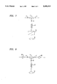
- FIG. 5 Another embodiment showing yet another return means is depicted in FIG. 5.
- An optical fiber is connected to the first and third ports enabling the signal to return through the dispersion compensating fiber 11 to circulator 5 and then to system fiber 7. Additional function may be inserted in the loop. For example, there may be filter, amplifier, etc.
- the dispersion compensating fiber may also be doped with rare earth ions and function as a fiber amplifier. Such an embodiment is depicted in FIG. 6 with the Er doped DCF shown as element 63. When pumped, this fiber provides dispersion compensation while counteracting propagation loss with gain. Operation will be readily understood without detailed explanation.
- Reflection or return of light through the DCF has previously been mentioned as advantageous because it reduces the amount of DCF required for the system.
- There is another advantage of having the light pass twice through the DCF which will be apparent from consideration of FIG. 7.
- the rotator and mirror are shown as separate, discrete elements, their functions may be combined in a single element.
- the rotator rotates the polarization by 90 degrees and compensates for polarization mode dispersion of the optical components undergoing the second pass.
- the components include the DCF, the fiber amplifier, the multiplexer, etc.
- the DCF has relatively high losses, and it may be desirable to amplify the signal before it goes through this fiber.
- Such apparatus is shown in FIG. 8 which has a preamplifier 81 and a power amplifier 83. These components are well-known to these skilled in the art. This embodiment should result in a improved signal-to-noise ratio as compared to the embodiments that do not have preamplifier 81 and power amplifier 83.
- Either or both preamplifier 81 and power amplifier 83 may use fiber amplifiers. These fiber amplifiers may be remotely pumped by light sources in the transmitter or receiver.
- the multiplexer and pump laser depicted in FIG. 3 may be connected to the second port of the optical circulator rather than the first port.
- the signals may be amplified in bidirectional systems for single or multiple wavelengths.
- the description has been in terms of fibers, other types of waveguides may be used.
Landscapes
- Physics & Mathematics (AREA)
- Chemical & Material Sciences (AREA)
- Dispersion Chemistry (AREA)
- General Physics & Mathematics (AREA)
- Optics & Photonics (AREA)
- Electromagnetism (AREA)
- Engineering & Computer Science (AREA)
- Computer Networks & Wireless Communication (AREA)
- Signal Processing (AREA)
- Optical Communication System (AREA)
- Lasers (AREA)
Abstract
Description
Claims (21)
Priority Applications (4)
| Application Number | Priority Date | Filing Date | Title |
|---|---|---|---|
| US08/168,722 US5404413A (en) | 1993-12-14 | 1993-12-14 | Optical circulator for dispersion compensation |
| DE69431588T DE69431588D1 (en) | 1993-12-14 | 1994-12-01 | Optical circulator for dispersion compensation |
| EP94308915A EP0658988B1 (en) | 1993-12-14 | 1994-12-01 | Optical circulator for dispersion compensation |
| JP6332348A JPH07202798A (en) | 1993-12-14 | 1994-12-14 | Light communication system |
Applications Claiming Priority (1)
| Application Number | Priority Date | Filing Date | Title |
|---|---|---|---|
| US08/168,722 US5404413A (en) | 1993-12-14 | 1993-12-14 | Optical circulator for dispersion compensation |
Publications (1)
| Publication Number | Publication Date |
|---|---|
| US5404413A true US5404413A (en) | 1995-04-04 |
Family
ID=22612675
Family Applications (1)
| Application Number | Title | Priority Date | Filing Date |
|---|---|---|---|
| US08/168,722 Expired - Lifetime US5404413A (en) | 1993-12-14 | 1993-12-14 | Optical circulator for dispersion compensation |
Country Status (4)
| Country | Link |
|---|---|
| US (1) | US5404413A (en) |
| EP (1) | EP0658988B1 (en) |
| JP (1) | JPH07202798A (en) |
| DE (1) | DE69431588D1 (en) |
Cited By (43)
| Publication number | Priority date | Publication date | Assignee | Title |
|---|---|---|---|---|
| US5572357A (en) * | 1994-02-14 | 1996-11-05 | Sumitomo Electric Industries, Ltd. | Optical system for amplifying signal light |
| US5596448A (en) * | 1994-09-27 | 1997-01-21 | Fujitsu Limited | Dispersion compensator and optical amplifier |
| US5598294A (en) * | 1994-08-18 | 1997-01-28 | Matsushita Electric Industrial Co., Ltd. | Optical fiber amplifier and optical fiber communication system |
| US5600482A (en) * | 1994-03-10 | 1997-02-04 | Nec Corporation | Optical amplifier circuit capable of carrying out stable amplification |
| US5608825A (en) * | 1996-02-01 | 1997-03-04 | Jds Fitel Inc. | Multi-wavelength filtering device using optical fiber Bragg grating |
| US5640268A (en) * | 1995-02-28 | 1997-06-17 | Alcatel N.V. | Optical fiber amplifier with two directional pumping |
| US5680491A (en) * | 1992-09-29 | 1997-10-21 | Sumitomo Electric Industries, Ltd. | Optical fiber dispersion compensation device for optical communication system |
| US5701188A (en) * | 1995-03-15 | 1997-12-23 | Sumitomo Electric Industries, Ltd. | Chromatic dispersion compensator and chromatic dispersion compensating optical communication system |
| WO1998001781A1 (en) * | 1996-07-06 | 1998-01-15 | Northern Telecom Limited | Dispersion compensating waveguide for optical transmission systems |
| US5731891A (en) * | 1995-02-20 | 1998-03-24 | Lucent Technologies Inc. | Optical amplifier |
| US5903683A (en) * | 1997-09-10 | 1999-05-11 | The United States Of America As Represented By The National Security Agency | Device for modulating an optical signal using a single wave guide |
| US5974206A (en) * | 1997-12-19 | 1999-10-26 | Northern Telecom Limited | Dispersion compensation with low polarization mode dispersion |
| WO1999062202A1 (en) * | 1998-05-27 | 1999-12-02 | Mci Worldcom, Inc. | Bidirectional dispersion compensation system |
| US6055081A (en) * | 1995-03-15 | 2000-04-25 | Sumitomo Electric Industries, Ltd. | Chromatic dispersion compensator and chromatic dispersion compensating optical communication system |
| EP1041753A1 (en) * | 1999-03-31 | 2000-10-04 | Alcatel | Device and method for compensating the polarisation mode dispersion according to the chromatic dispersion in an optical transmission system |
| US6151157A (en) * | 1997-06-30 | 2000-11-21 | Uniphase Telecommunications Products, Inc. | Dynamic optical amplifier |
| EP1063545A1 (en) * | 1999-06-23 | 2000-12-27 | Nortel Networks Limited | Dispersion compensation |
| EP1067414A1 (en) * | 1999-07-08 | 2001-01-10 | Alcatel | Fibre optic Bragg grating filter with a constant group delay time for the band region in use |
| US6178038B1 (en) * | 1998-02-20 | 2001-01-23 | Ciena Corporation | Optical amplifier having an improved noise figure |
| US6198859B1 (en) * | 1996-12-05 | 2001-03-06 | Nec Corporation | Dispersion compensating device using dispersion compensating fiber module |
| US6198572B1 (en) * | 1996-05-02 | 2001-03-06 | Fujitsu Limited | Controller which controls a variable optical attenuator to control the power level of a wavelength-multiplexed optical signal when the number of channels are varied |
| US6204945B1 (en) * | 1996-07-09 | 2001-03-20 | Fujitsu Limited | Signal light outputting apparatus and optical transmission system having signal light outputting apparatus |
| FR2799068A1 (en) * | 1999-09-09 | 2001-03-30 | Nec Corp | High capacity wavelength multiplexing optical transmission system dispersion compensation having signal input separator inputting and dispersion compensation/faraday rotator sent with returned signal passing through compensator/third port |
| US6236495B1 (en) * | 1997-10-07 | 2001-05-22 | Lucent Technologies Inc. | Optical dispersion compensation |
| US6480312B1 (en) | 1997-12-16 | 2002-11-12 | Sumitomo Electric Industries, Ltd. | Dispersion compensating system used for bi-directional optical communication |
| US6483957B1 (en) | 2001-01-29 | 2002-11-19 | 3M Innovative Properties Company | MEMS-based polarization mode dispersion compensator |
| US20030048977A1 (en) * | 2001-09-11 | 2003-03-13 | Hwang Seong-Taek | Dispersion-compensated optical fiber amplifier |
| US6542290B1 (en) * | 1994-05-06 | 2003-04-01 | Hitachi, Ltd. | Optical amplifier |
| US6556732B1 (en) | 2000-06-07 | 2003-04-29 | Corning Incorporated | All fiber polarization mode dispersion compensator |
| US6577424B1 (en) * | 2000-01-10 | 2003-06-10 | Tyco Telecommunications (Us) Inc. | Chromatic dispersion compensator providing dispersion compensation to select channels of a wavelength division multiplexed signal |
| US6587606B1 (en) * | 2000-10-20 | 2003-07-01 | Corning Incorporated | Waveguide fiber dispersion compensating regenerator |
| WO2003040777A3 (en) * | 2001-11-02 | 2003-08-14 | Worldcom Inc | Integrated adaptive chromatic dispersion/polarization mode dispersion compensation system |
| US20030156316A1 (en) * | 2002-02-20 | 2003-08-21 | Hwang Seong-Taek | Dispersion-compensated raman optical fiber amplifier |
| US20030168745A1 (en) * | 2002-03-05 | 2003-09-11 | Yu-Sik Kim | Multi-layer structure for reducing capacitance and manufacturing method thereof |
| US6636674B2 (en) * | 2000-09-21 | 2003-10-21 | Kwangju Institute Of Science & Technology | Figure-8 optical fiber pulse laser using a dispersion imbalanced nonlinear optical loop mirror |
| US20040020942A1 (en) * | 2000-11-17 | 2004-02-05 | Nikolaus Ingenhoven | Device and system for dispensing or aspirating/dispensing liquid samples |
| US20040047549A1 (en) * | 2002-09-06 | 2004-03-11 | Corvis Corporation | Optical communications systems including a branching unit and associated devices and methods |
| US20040109224A1 (en) * | 2002-12-09 | 2004-06-10 | Kim Sung-Tae | Reflective dispersion-compensation optical amplifier |
| US20040196544A1 (en) * | 2002-12-20 | 2004-10-07 | Rosolem Joao Batista | Double pass optical amplifier with unidirectional compensation of chromatic dispersion and obstruction of backscattering |
| US20050100342A1 (en) * | 2003-11-12 | 2005-05-12 | Lg Electronics Inc. | Optical dispersion compensation system and method in optical communication system |
| US20050135814A1 (en) * | 2003-12-17 | 2005-06-23 | Stephen Courtney | Apparatus and method for simulating a length of optical fiber |
| US20130028551A1 (en) * | 2011-07-25 | 2013-01-31 | Harris Corporation, Corporation Of The State Of Delaware | Tunable rf filter device using optical waveguides with dispersion slopes of opposite signs and related methods |
| US20130028552A1 (en) * | 2011-07-25 | 2013-01-31 | Harris Corporation, Corporation Of The State Of Delaware | Tunable rf filter device using optical waveguide paths with splitter and combiner pairs and related methods |
Families Citing this family (8)
| Publication number | Priority date | Publication date | Assignee | Title |
|---|---|---|---|---|
| EP1841022A3 (en) * | 1995-03-20 | 2009-12-02 | Fujitsu Limited | Apparatus and method for processing an optical signal |
| GB9526183D0 (en) | 1995-12-21 | 1996-02-21 | Stc Submarine Systems Ltd | Dispersion slope equalisaion for wdm systems wih branches |
| JPH10163962A (en) * | 1996-11-25 | 1998-06-19 | Nec Corp | Automatic dispersion compensation optical transmission system |
| KR100269171B1 (en) | 1997-08-28 | 2000-10-16 | 윤종용 | Optical fiber dispersion compensator |
| DE19806584C1 (en) * | 1998-02-17 | 1999-08-19 | Siemens Ag | Bidirectional dispersion compensator |
| JP3468097B2 (en) * | 1998-03-17 | 2003-11-17 | 日立電線株式会社 | Ultra-wideband chromatic dispersion compensation / amplification device |
| DE19819204C1 (en) | 1998-04-29 | 1999-09-30 | Siemens Ag | Trimming two-point exhaust gas sensor indication, to compensate behavioral shift due to aging and poisoning |
| JP3682374B2 (en) * | 1998-07-07 | 2005-08-10 | 古河電気工業株式会社 | Optical fiber type optical components |
Citations (6)
| Publication number | Priority date | Publication date | Assignee | Title |
|---|---|---|---|---|
| US4606605A (en) * | 1984-06-29 | 1986-08-19 | At&T Bell Laboratories | Optical fiber having in-line polarization filter |
| US4830451A (en) * | 1986-03-05 | 1989-05-16 | American Telephone And Telegraph Company | Technique and apparatus for fabricating a fiber Fabry-Perot etalon |
| US4953939A (en) * | 1984-07-11 | 1990-09-04 | Stc Plc | Optical fibre transmission systems |
| US4991938A (en) * | 1989-04-07 | 1991-02-12 | Gte Laboratories Incorporated | Quasi-achromatic optical isolators and circulators using prisms with total internal fresnel reflection |
| US5023947A (en) * | 1989-11-01 | 1991-06-11 | At&T Bell Laboratories | Optical equalization receiver for lightwave communication systems |
| US5202791A (en) * | 1991-01-16 | 1993-04-13 | Nec Corporation | Optical amplifying apparatus |
Family Cites Families (2)
| Publication number | Priority date | Publication date | Assignee | Title |
|---|---|---|---|---|
| DE69224340T2 (en) * | 1991-09-30 | 1998-06-04 | Nippon Electric Co | Two-way repeater with optical amplification |
| US5361319A (en) * | 1992-02-04 | 1994-11-01 | Corning Incorporated | Dispersion compensating devices and systems |
-
1993
- 1993-12-14 US US08/168,722 patent/US5404413A/en not_active Expired - Lifetime
-
1994
- 1994-12-01 EP EP94308915A patent/EP0658988B1/en not_active Expired - Lifetime
- 1994-12-01 DE DE69431588T patent/DE69431588D1/en not_active Expired - Lifetime
- 1994-12-14 JP JP6332348A patent/JPH07202798A/en active Pending
Patent Citations (6)
| Publication number | Priority date | Publication date | Assignee | Title |
|---|---|---|---|---|
| US4606605A (en) * | 1984-06-29 | 1986-08-19 | At&T Bell Laboratories | Optical fiber having in-line polarization filter |
| US4953939A (en) * | 1984-07-11 | 1990-09-04 | Stc Plc | Optical fibre transmission systems |
| US4830451A (en) * | 1986-03-05 | 1989-05-16 | American Telephone And Telegraph Company | Technique and apparatus for fabricating a fiber Fabry-Perot etalon |
| US4991938A (en) * | 1989-04-07 | 1991-02-12 | Gte Laboratories Incorporated | Quasi-achromatic optical isolators and circulators using prisms with total internal fresnel reflection |
| US5023947A (en) * | 1989-11-01 | 1991-06-11 | At&T Bell Laboratories | Optical equalization receiver for lightwave communication systems |
| US5202791A (en) * | 1991-01-16 | 1993-04-13 | Nec Corporation | Optical amplifying apparatus |
Non-Patent Citations (10)
| Title |
|---|
| "All-Optical, Fiber-Based 1550 nm Dispersion Compensation in a 10 Gbit/s, 150 km Transmission Experiment over 1310 nm Optimized Fiber", J. M. Dugan et al., Alcatel Network Systems, Inc., A. J. Antos et al., Opto-Electronic Group, Corning Incorporated, OFC 92, San Jose, Calif., pp. 367-370, 1992 (no month available). |
| "Dispersion Compensation with Optical Ring Resonator in Coherent Optical Transmission Systems", Shigeki Kitajima et al., Central Research Laboratory, Hitachi Ltd., ECOC 93, Montreaux, Switzerland, (4 pages), 1993, no month available. |
| "High Performance Dispersion-Compensating Fiber and its Application to Upgrading of 1.31 μm Optimized System", M. Onishi et al., Sumitomo Electric Industries, Ltd., ECOC 93, Montreux, Switzerland, (4 pages), 1993, no month available. |
| "Improvement in In-Line Amplifier Transmission Distance with Group-Velocity-Dispersion Compensation", Akira Naka and Shigeru Saito, NTT Transmission Systems Laboratories, Optical Amplifiers & Their Applications, Jul. 4-6, Yokohama, Japan, 1993, pp. 30-33. |
| "The Realization of Broad-Band Dispersion Compensation using the Multicladding Waveguide Structure", A. V. Belov et al., General Physics Institute, Russian Academy of Sciences, A. N. Guryanov et al., Institute of Chemistry of High Purity Substances, Russian Academy of Sciences, ECOC 93, Montreaux, Switzerland, (4 pages), 1993, no month available. |
| All Optical, Fiber Based 1550 nm Dispersion Compensation in a 10 Gbit/s, 150 km Transmission Experiment over 1310 nm Optimized Fiber , J. M. Dugan et al., Alcatel Network Systems, Inc., A. J. Antos et al., Opto Electronic Group, Corning Incorporated, OFC 92, San Jose, Calif., pp. 367 370, 1992 (no month available). * |
| Dispersion Compensation with Optical Ring Resonator in Coherent Optical Transmission Systems , Shigeki Kitajima et al., Central Research Laboratory, Hitachi Ltd., ECOC 93, Montreaux, Switzerland, (4 pages), 1993, no month available. * |
| High Performance Dispersion Compensating Fiber and its Application to Upgrading of 1.31 m Optimized System , M. Onishi et al., Sumitomo Electric Industries, Ltd., ECOC 93, Montreux, Switzerland, (4 pages), 1993, no month available. * |
| Improvement in In Line Amplifier Transmission Distance with Group Velocity Dispersion Compensation , Akira Naka and Shigeru Saito, NTT Transmission Systems Laboratories, Optical Amplifiers & Their Applications, Jul. 4 6, Yokohama, Japan, 1993, pp. 30 33. * |
| The Realization of Broad Band Dispersion Compensation using the Multicladding Waveguide Structure , A. V. Belov et al., General Physics Institute, Russian Academy of Sciences, A. N. Guryanov et al., Institute of Chemistry of High Purity Substances, Russian Academy of Sciences, ECOC 93, Montreaux, Switzerland, (4 pages), 1993, no month available. * |
Cited By (67)
| Publication number | Priority date | Publication date | Assignee | Title |
|---|---|---|---|---|
| US5680491A (en) * | 1992-09-29 | 1997-10-21 | Sumitomo Electric Industries, Ltd. | Optical fiber dispersion compensation device for optical communication system |
| US5572357A (en) * | 1994-02-14 | 1996-11-05 | Sumitomo Electric Industries, Ltd. | Optical system for amplifying signal light |
| US5600482A (en) * | 1994-03-10 | 1997-02-04 | Nec Corporation | Optical amplifier circuit capable of carrying out stable amplification |
| US6542290B1 (en) * | 1994-05-06 | 2003-04-01 | Hitachi, Ltd. | Optical amplifier |
| US5598294A (en) * | 1994-08-18 | 1997-01-28 | Matsushita Electric Industrial Co., Ltd. | Optical fiber amplifier and optical fiber communication system |
| US5596448A (en) * | 1994-09-27 | 1997-01-21 | Fujitsu Limited | Dispersion compensator and optical amplifier |
| US5731891A (en) * | 1995-02-20 | 1998-03-24 | Lucent Technologies Inc. | Optical amplifier |
| US5640268A (en) * | 1995-02-28 | 1997-06-17 | Alcatel N.V. | Optical fiber amplifier with two directional pumping |
| US5701188A (en) * | 1995-03-15 | 1997-12-23 | Sumitomo Electric Industries, Ltd. | Chromatic dispersion compensator and chromatic dispersion compensating optical communication system |
| AU700400B2 (en) * | 1995-03-15 | 1999-01-07 | Sumitomo Electric Industries, Ltd. | Chromatic dispersion compensator and chromatic dispersion compensating optical communication system |
| US6055081A (en) * | 1995-03-15 | 2000-04-25 | Sumitomo Electric Industries, Ltd. | Chromatic dispersion compensator and chromatic dispersion compensating optical communication system |
| US5608825A (en) * | 1996-02-01 | 1997-03-04 | Jds Fitel Inc. | Multi-wavelength filtering device using optical fiber Bragg grating |
| US6198572B1 (en) * | 1996-05-02 | 2001-03-06 | Fujitsu Limited | Controller which controls a variable optical attenuator to control the power level of a wavelength-multiplexed optical signal when the number of channels are varied |
| CN100477563C (en) * | 1996-05-02 | 2009-04-08 | 富士通株式会社 | Controller for controlling changeable light attenuator |
| US6215929B1 (en) | 1996-07-06 | 2001-04-10 | Nortel Networks Limited | Dispersion compensating waveguide for optical transmission systems |
| WO1998001781A1 (en) * | 1996-07-06 | 1998-01-15 | Northern Telecom Limited | Dispersion compensating waveguide for optical transmission systems |
| GB2315177A (en) * | 1996-07-06 | 1998-01-21 | Northern Telecom Ltd | Dispersion compensating waveguide for optical transmission systems |
| US6204945B1 (en) * | 1996-07-09 | 2001-03-20 | Fujitsu Limited | Signal light outputting apparatus and optical transmission system having signal light outputting apparatus |
| US6198859B1 (en) * | 1996-12-05 | 2001-03-06 | Nec Corporation | Dispersion compensating device using dispersion compensating fiber module |
| US6151157A (en) * | 1997-06-30 | 2000-11-21 | Uniphase Telecommunications Products, Inc. | Dynamic optical amplifier |
| US5903683A (en) * | 1997-09-10 | 1999-05-11 | The United States Of America As Represented By The National Security Agency | Device for modulating an optical signal using a single wave guide |
| US6236495B1 (en) * | 1997-10-07 | 2001-05-22 | Lucent Technologies Inc. | Optical dispersion compensation |
| US6480312B1 (en) | 1997-12-16 | 2002-11-12 | Sumitomo Electric Industries, Ltd. | Dispersion compensating system used for bi-directional optical communication |
| US5974206A (en) * | 1997-12-19 | 1999-10-26 | Northern Telecom Limited | Dispersion compensation with low polarization mode dispersion |
| US6178038B1 (en) * | 1998-02-20 | 2001-01-23 | Ciena Corporation | Optical amplifier having an improved noise figure |
| WO1999062202A1 (en) * | 1998-05-27 | 1999-12-02 | Mci Worldcom, Inc. | Bidirectional dispersion compensation system |
| US6157477A (en) * | 1998-05-27 | 2000-12-05 | Mci Communications Corporations | Bidirectional dispersion compensation system |
| US6317240B1 (en) | 1999-03-31 | 2001-11-13 | Alcatel | System for and a method of compensating polarization dispersion in an optical transmission system |
| FR2791835A1 (en) * | 1999-03-31 | 2000-10-06 | Cit Alcatel | DEVICE AND METHOD FOR COMPENSATING FOR POLARIZATION DISPERSION IN AN OPTICAL TRANSMISSION SYSTEM |
| EP1041753A1 (en) * | 1999-03-31 | 2000-10-04 | Alcatel | Device and method for compensating the polarisation mode dispersion according to the chromatic dispersion in an optical transmission system |
| US6438287B1 (en) | 1999-06-23 | 2002-08-20 | Nortel Networks Limited | Dispersion compensation |
| EP1063545A1 (en) * | 1999-06-23 | 2000-12-27 | Nortel Networks Limited | Dispersion compensation |
| FR2796164A1 (en) * | 1999-07-08 | 2001-01-12 | Cit Alcatel | BRAGG NETWORK FIBER OPTICAL FILTER WITH CONSTANT GROUP TIME RESPONSE IN THE USEFUL BAND |
| US6381069B1 (en) | 1999-07-08 | 2002-04-30 | Alcatel | Fiber Bragg grating optical filter with a constant group-delay response in its working band |
| EP1067414A1 (en) * | 1999-07-08 | 2001-01-10 | Alcatel | Fibre optic Bragg grating filter with a constant group delay time for the band region in use |
| FR2799068A1 (en) * | 1999-09-09 | 2001-03-30 | Nec Corp | High capacity wavelength multiplexing optical transmission system dispersion compensation having signal input separator inputting and dispersion compensation/faraday rotator sent with returned signal passing through compensator/third port |
| US6577424B1 (en) * | 2000-01-10 | 2003-06-10 | Tyco Telecommunications (Us) Inc. | Chromatic dispersion compensator providing dispersion compensation to select channels of a wavelength division multiplexed signal |
| US6556732B1 (en) | 2000-06-07 | 2003-04-29 | Corning Incorporated | All fiber polarization mode dispersion compensator |
| US6636674B2 (en) * | 2000-09-21 | 2003-10-21 | Kwangju Institute Of Science & Technology | Figure-8 optical fiber pulse laser using a dispersion imbalanced nonlinear optical loop mirror |
| US6587606B1 (en) * | 2000-10-20 | 2003-07-01 | Corning Incorporated | Waveguide fiber dispersion compensating regenerator |
| US20040020942A1 (en) * | 2000-11-17 | 2004-02-05 | Nikolaus Ingenhoven | Device and system for dispensing or aspirating/dispensing liquid samples |
| US6483957B1 (en) | 2001-01-29 | 2002-11-19 | 3M Innovative Properties Company | MEMS-based polarization mode dispersion compensator |
| US20030048977A1 (en) * | 2001-09-11 | 2003-03-13 | Hwang Seong-Taek | Dispersion-compensated optical fiber amplifier |
| US6785043B2 (en) * | 2001-09-11 | 2004-08-31 | Samsung Electronics Co., Ltd. | Dispersion-compensated optical fiber amplifier |
| WO2003040777A3 (en) * | 2001-11-02 | 2003-08-14 | Worldcom Inc | Integrated adaptive chromatic dispersion/polarization mode dispersion compensation system |
| US6889011B1 (en) | 2001-11-02 | 2005-05-03 | Mci, Inc. | Integrated adaptive chromatic dispersion/polarization mode dispersion compensation system |
| US6898003B2 (en) * | 2002-02-20 | 2005-05-24 | Samsung Electronics Co., Ltd. | Dispersion-compensated Raman optical fiber amplifier |
| EP1339178A1 (en) * | 2002-02-20 | 2003-08-27 | Samsung Electronics Co., Ltd. | Dispersion-compensated raman optical fiber amplifier |
| US20030156316A1 (en) * | 2002-02-20 | 2003-08-21 | Hwang Seong-Taek | Dispersion-compensated raman optical fiber amplifier |
| US20030168745A1 (en) * | 2002-03-05 | 2003-09-11 | Yu-Sik Kim | Multi-layer structure for reducing capacitance and manufacturing method thereof |
| US6747292B2 (en) | 2002-03-05 | 2004-06-08 | Samsung Electronics Co., Ltd. | Multi-layer structure for reducing capacitance and manufacturing method thereof |
| US6768833B2 (en) * | 2002-09-06 | 2004-07-27 | Corvis Corporation | Optical communications systems including a branching unit and associated devices and methods |
| WO2004023169A3 (en) * | 2002-09-06 | 2005-01-13 | Corvis Corp | Optical communications systems including a branching unit and associated devices and methods |
| US20040047549A1 (en) * | 2002-09-06 | 2004-03-11 | Corvis Corporation | Optical communications systems including a branching unit and associated devices and methods |
| US20040109224A1 (en) * | 2002-12-09 | 2004-06-10 | Kim Sung-Tae | Reflective dispersion-compensation optical amplifier |
| US6992817B2 (en) * | 2002-12-20 | 2006-01-31 | Fundaçäo CPqD-Centro de Pesquisa e Desenvolvimento em Telecomunicaçöes | Double pass optical amplifier with unidirectional compensation of chromatic dispersion and obstruction of backscattering |
| US20040196544A1 (en) * | 2002-12-20 | 2004-10-07 | Rosolem Joao Batista | Double pass optical amplifier with unidirectional compensation of chromatic dispersion and obstruction of backscattering |
| US20050100342A1 (en) * | 2003-11-12 | 2005-05-12 | Lg Electronics Inc. | Optical dispersion compensation system and method in optical communication system |
| US20050135814A1 (en) * | 2003-12-17 | 2005-06-23 | Stephen Courtney | Apparatus and method for simulating a length of optical fiber |
| US20130028551A1 (en) * | 2011-07-25 | 2013-01-31 | Harris Corporation, Corporation Of The State Of Delaware | Tunable rf filter device using optical waveguides with dispersion slopes of opposite signs and related methods |
| US20130028552A1 (en) * | 2011-07-25 | 2013-01-31 | Harris Corporation, Corporation Of The State Of Delaware | Tunable rf filter device using optical waveguide paths with splitter and combiner pairs and related methods |
| US8897607B2 (en) * | 2011-07-25 | 2014-11-25 | Harris Corporation | Tunable RF filter device using optical waveguides with dispersion slopes of opposite signs and related methods |
| US20150036966A1 (en) * | 2011-07-25 | 2015-02-05 | Harris Corporation | Tunable rf filter device using optical waveguides with dispersion slopes of opposite signs and related methods |
| US8971671B2 (en) * | 2011-07-25 | 2015-03-03 | Harris Corporation | Tunable RF filter device using optical waveguide paths with splitter and combiner pairs and related methods |
| US9002143B2 (en) * | 2011-07-25 | 2015-04-07 | Harris Corporation | Tunable RF filter device using optical waveguides with dispersion slopes of opposite signs and related methods |
| US20150125108A1 (en) * | 2011-07-25 | 2015-05-07 | Harris Corporation | Tunable rf filter device using optical waveguide paths with splitter and combiner pairs and related methods |
| US9116366B2 (en) * | 2011-07-25 | 2015-08-25 | Harris Corporation | Tunable RF filter device using optical waveguide paths with splitter and combiner pairs and related methods |
Also Published As
| Publication number | Publication date |
|---|---|
| DE69431588D1 (en) | 2002-11-28 |
| EP0658988A1 (en) | 1995-06-21 |
| EP0658988B1 (en) | 2002-10-23 |
| JPH07202798A (en) | 1995-08-04 |
Similar Documents
| Publication | Publication Date | Title |
|---|---|---|
| US5404413A (en) | Optical circulator for dispersion compensation | |
| US6263139B1 (en) | Optical transmission system with group velocity dispersion compensation | |
| US5082343A (en) | Isolated optical coupler | |
| US6359725B1 (en) | Multi-stage optical amplifier and broadband communication system | |
| US5940208A (en) | Switchable fiber optic device for fiber transmission system and components thereof | |
| US5596448A (en) | Dispersion compensator and optical amplifier | |
| US5917635A (en) | Optical repeaters for single-and multi-wavelength operation with dispersion equalization | |
| CA2092146C (en) | Optical amplifier with automatic self adjusting gain spectrum | |
| US6417961B1 (en) | Optical amplifiers with dispersion compensation | |
| JPH05509202A (en) | optical waveguide amplifier | |
| EP0660468B1 (en) | Bidirectional optical amplifier | |
| EP0909047B1 (en) | Optical dispersion compensation | |
| US6304691B1 (en) | Wavelength division multiplexed optical communication system having reduced short wavelength loss | |
| US6204958B1 (en) | Optical amplifier having a substantially flat gain spectrum | |
| US20040085624A1 (en) | Dual fiber optic amplifier with shared pump source | |
| US6934078B2 (en) | Dispersion-compensated erbium-doped fiber amplifier | |
| EP0843199B1 (en) | Optical channel equaliser using a photoinduced gain grating and corresponding method | |
| EP1304775B1 (en) | Dispersion-compensated optical fiber amplifier | |
| US6862132B1 (en) | Suppression of double rayleigh backscattering and pump reuse in a raman amplifier | |
| KR100904292B1 (en) | Gain flattening utilizing a two-stage erbium-based amplifier | |
| KR20030069362A (en) | Dispersion-compensated raman optical fiber amplifier | |
| US20070264024A1 (en) | Bi-directional application of a dispersion compensating module in a regional system | |
| US7068879B2 (en) | Gain flattening device for an optical fiber amplifier | |
| RU2172562C2 (en) | Bi-directional optical amplifier and manner of bi-directional communication | |
| EP0820127A1 (en) | Arrangement for reducing insertion loss impairment of optical amplifiers |
Legal Events
| Date | Code | Title | Description |
|---|---|---|---|
| AS | Assignment |
Owner name: AMERICAN TELEPHONE AND TELEGRAPH COMPANY, NEW YORK Free format text: ASSIGNMENT OF ASSIGNORS INTEREST;ASSIGNORS:DELAVAUX, JEAN-MARC P.;OGAWA, KINICHIRO;REEL/FRAME:006828/0036 Effective date: 19931214 |
|
| STCF | Information on status: patent grant |
Free format text: PATENTED CASE |
|
| AS | Assignment |
Owner name: AT&T CORP., NEW YORK Free format text: ASSIGNMENT OF ASSIGNORS INTEREST;ASSIGNOR:AMERICAN TELELPHONE AND TELEGRAPH COMPANY;REEL/FRAME:007527/0274 Effective date: 19940420 Owner name: AT&T IPM CORP., FLORIDA Free format text: ASSIGNMENT OF ASSIGNORS INTEREST;ASSIGNOR:AT&T CORP.;REEL/FRAME:007528/0038 Effective date: 19950523 |
|
| FEPP | Fee payment procedure |
Free format text: PAYOR NUMBER ASSIGNED (ORIGINAL EVENT CODE: ASPN); ENTITY STATUS OF PATENT OWNER: LARGE ENTITY |
|
| FPAY | Fee payment |
Year of fee payment: 4 |
|
| FPAY | Fee payment |
Year of fee payment: 8 |
|
| FPAY | Fee payment |
Year of fee payment: 12 |
|
| AS | Assignment |
Owner name: CREDIT SUISSE AG, NEW YORK Free format text: SECURITY INTEREST;ASSIGNOR:ALCATEL-LUCENT USA INC.;REEL/FRAME:030510/0627 Effective date: 20130130 |
|
| AS | Assignment |
Owner name: ALCATEL-LUCENT USA INC., NEW JERSEY Free format text: RELEASE BY SECURED PARTY;ASSIGNOR:CREDIT SUISSE AG;REEL/FRAME:033950/0001 Effective date: 20140819 |