US540239A - Of same place - Google Patents
Of same place Download PDFInfo
- Publication number
- US540239A US540239A US540239DA US540239A US 540239 A US540239 A US 540239A US 540239D A US540239D A US 540239DA US 540239 A US540239 A US 540239A
- Authority
- US
- United States
- Prior art keywords
- battery
- telephone
- current
- subscriber
- line
- Prior art date
- Legal status (The legal status is an assumption and is not a legal conclusion. Google has not performed a legal analysis and makes no representation as to the accuracy of the status listed.)
- Expired - Lifetime
Links
- 238000012360 testing method Methods 0.000 description 18
- 239000004020 conductor Substances 0.000 description 17
- 230000000994 depressogenic effect Effects 0.000 description 2
- 230000006698 induction Effects 0.000 description 2
- 238000004519 manufacturing process Methods 0.000 description 2
- 230000000881 depressing effect Effects 0.000 description 1
- NRUQNUIWEUZVLI-UHFFFAOYSA-O diethanolammonium nitrate Chemical compound [O-][N+]([O-])=O.OCC[NH2+]CCO NRUQNUIWEUZVLI-UHFFFAOYSA-O 0.000 description 1
- 230000000694 effects Effects 0.000 description 1
- 230000005611 electricity Effects 0.000 description 1
- 230000004048 modification Effects 0.000 description 1
- 238000012986 modification Methods 0.000 description 1
- 230000000284 resting effect Effects 0.000 description 1
Images

Classifications
-
- H—ELECTRICITY
- H04—ELECTRIC COMMUNICATION TECHNIQUE
- H04M—TELEPHONIC COMMUNICATION
- H04M5/00—Manual exchanges
- H04M5/04—Arrangements for indicating calls or supervising connections for calling or clearing
- H04M5/06—Arrangements for indicating calls or supervising connections for calling or clearing affording automatic call distribution
Definitions
- My invention relates to telephone systems, and more particularly to a system of that class commonly known as the Law system.
- the object of my invention is to provide improved means for testing at one of the multiple boards to determine whether a line is busy and a connection has been made therewith at another of the multiple boards.
- a further object of my invention is to replace the primary battery usually employed in the local circuit at the subscribers station containing the transmitter by a storage battery located in the main telephone line and adapted to be charged by a battery at the central station.
- the substation is connected with a head telephone worn by the operator at the central station by means of a talking circuit and the subscriber by depressing a key connects his telephone in circuit with the operators telephone and gives the number of his -own telephone and that of the called subscriber.
- the operator picks up a plug connected with a source of electricity, as a battery, and touches the tip of the plug to the spring jack of the calling subscriber, thus completing circuit through his bell to sound the same and inform him that his call has been received.
- the subscriber then releases the key and thus cuts his telephone out of circuit with the operators telephone.
- the central station I provide a battery which is connected with each of the lines of the exchange or with each of agroup of lines by branches, the branches connecting the battery with the several lines being in multiple with one another, and a resistance coil being placed in each branch to out down the current flowing; over the line and through the subscribers bell to such an extent that the passage of the current through the bell will not ring the same.
- All the spring jacks in the exchange are thus connected with a source of current and the operator is provided with a testing plug connected through a sounding relay whereby she may connect her relay in ICC through the sounding relay, but the current will be of insufficient strength to sound the relay; and the operator hearing no sound, will know that the line is not busy.
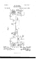
- Figure 1 illustrates two subscribers lines connected together for conversation in accordance with my invention, the sub-stations being provided with direct-current make-andbreak bells.
- Fig. 2 is a similar view showing the sub-stations provided with alternatingcurrent or magneto bells.
- the operators head telephone a is connected by lines a a with springs a a which rest upon contacts a a provided upon a plate adapted to be moved by key a
- springs a a which rest upon contacts a a provided upon a plate adapted to be moved by key a
- contacts 19 11 between which are connected by conductors b b the subscribers receiver 0 and the secondary of his transmitter (1.
- the contacts I) 13 rest springs 19 b the spring 19 being connected to ground by a conductor 1) and the spring I) being connected by a conductor 19 with a contact 6 against which the switch 1ever 6 is adapted to rest when the telephone is removed from the hook.
- the switch lever e normally makes connection with contact 6 connected through the make and break contacts f f of a vibratory bellf, the end of the conductor e being connected with a contact 6 provided upon the sliding plate a Between the conductors e and b the electromagnetf of the bell is connected.
- the switch hook e is connected with the central station bya line 9 connected with spring jacks g 9 y &c., upon the several switchboards at the exchange.
- the line g is connected with the pole of the grounded battery it by means of a branch wire 72. containing a resistance coil h
- the apparatus of subscriber B shown at the right, is the same as that provided in connection with subscriber A, and the parts have been indicated by similar reference letters.
- the line g of subscriber B is connected with the pole of battery h by means of a branch 72. containing a resistance coil 7%.
- the operator is provided with a number of connecting cords 2', provided with plugs upon the ends adapted to be inserted into the spring jacks of two lines to connect the same together.
- Each operator is provided with a testing plug carrying an insulated contact point 76' which is connected by means of conductor k with the pole of battery it.
- the tip 10 of the plug is connected with akey k normally resting against a contact 10 connected to ground through a sounding relay Z.
- connection with contact 10 is broken and key 70 closes against contact 70, thus connecting the tip 70 of the plug with conductor Z0
- the hook engages contact 6 thus closing the circuit of battery 0 through the primary of induction coil d, the battery obeing a storage battery, and placed in the main telephone line so that normally current from battery h passes through the branch 72/ over telephone line g through battery 0 and to ground through the subscribers bell.
- the resistance coil 71. placed in the branch h is of such magnitude that the current traversing the bell will be insufficient to ring the bell but will gradually charge the battery 0.
- Supposing subscriber A is desirous of talking with subscriber B, he depresses key of, thus bringing the contact plates 1) E) into engagement with springs a a the subscribers receiver c and transmitter 01 being thus connected in circuit with the head telephone a' of the operator.
- the subscriber then repeats his own number and that of the called subscriber.
- the operator takes up the plug it, depresses key 75 and touches the tip of the plug to the spring jack of the calling subscriber.
- Circuit is thus closed from battery It over conductor 70 to the tip of the plug, and thence through the springjack over line 9 of subscriber A to his telephone hook e, contact point e, conductor 19 to spring I), thence to contact plate e (the key a being depressed) thence by conductor 6 through the electromagnetf of the bell to ground.
- the hammer of the bell thus makes a single stroke to notify the calling subscriber that his order has been received. He then releases key 01. which is returned by means of a springto the position illustrated.
- the operator touches the testing plug 70 to the spring jack of the called subscriber, that is, the line of subscriber B.
- the testing plug being inserted in the springjack of the called subscriber, and it being determined that the line is not busy, theoperator depresses the key k thus sending current from battery 72 over conductor 7.0 through the testing plug and spring jack, and line g of subscriber B, thence through his telephone hook e, to contact e and to ground through his bell, the bell being thus rung to call the attention of the subscriber.
- Fig. 2 I have illustrated a modification of the subscribers station apparatus and also of the ringing apparatus at the central station, the vibratory bell being replaced by a magneto or alternating current bell m connected between the conductors e and b the make and break contacts f f interposed in the conductor 0 being thus dispensed with.
- a generator n is provided for ringing purposes, being connected with the insulated contact 70 upon the testing plug by conductor 70
- the resistance coils k h should possess su' fficient retardation effect to prevent the shunting of the voice currents passing over the line.
- the coils h and it may be adjusted for retardation only, and the voltage of the battery may be such as to give the necessary current for the charging of the storage batteries at the subscribers stations.
Landscapes
- Engineering & Computer Science (AREA)
- Signal Processing (AREA)
- Mobile Radio Communication Systems (AREA)
Description
(No Model.) 2 Sheets-Sheet 1.
I W. W. DEAN.
TELEPHONE SYSTEM.
.No. 540,239. Patented June 4, 1895..
.THE uonms FETER5 co.. mow-umol, vgsnmsmmu. c.
(No Model.) 2 Shets-8heet 2. W. W. DEAN.
TELEPHONE SYSTEM.
No. 540,239. Patented June 4, 1895.
15 PETERS co FNOTOLITHQ, wasumcron, u. c.
UNITED. STATES PATENT OFFICE.
WILLIAM W.. DEAN, OF ST. LOUIS, MISSOURI, ASSIGNOR TO THE BELL TELEPHONE COMPANY OF MISSOURI, OF SAME PLACE.
TELEPHONE SYSTEM.
SPECIFICATION forming part of Letters Patent No. 540,239, dated une 4, 1895. Application filed February 21, 1895, Serial No. 539,211- (No model.)
To all whom it may concern:
Be it known that 1, WILLIAM W. DEAN, a citizen of the UnitedStates, residing at St. Louis, in the State of Missouri, have invented a certain new and useful Improvement in Telephone Systems, (Case No. 3,) of which the following is a full, clear, concise, and exact description, reference being had to the accompanyin g drawings, forming a part of this specification.
My invention relates to telephone systems, and more particularly to a system of that class commonly known as the Law system.
The object of my invention is to provide improved means for testing at one of the multiple boards to determine whether a line is busy and a connection has been made therewith at another of the multiple boards.
A further object of my invention is to replace the primary battery usually employed in the local circuit at the subscribers station containing the transmitter by a storage battery located in the main telephone line and adapted to be charged by a battery at the central station.
The idea broadly of substituting a storage battery for the primary battery in the local circuitis not new with me, my invention consistingin the circuit connections whereby this feature may be adapted to the Law system. According to the Law system, the substation is connected with a head telephone worn by the operator at the central station by means of a talking circuit and the subscriber by depressing a key connects his telephone in circuit with the operators telephone and gives the number of his -own telephone and that of the called subscriber. The operator then picks up a plug connected with a source of electricity, as a battery, and touches the tip of the plug to the spring jack of the calling subscriber, thus completing circuit through his bell to sound the same and inform him that his call has been received. The subscriber then releases the key and thus cuts his telephone out of circuit with the operators telephone. To determine whether or not the called subscriber is busy, that is, whether or not his line is connected with another line at some other of the multiple boards, it has been the practice for the operator to touch the tip of her testing plug, which is connected with a source of current, to the spring jack of the called subscriber. If the subscriber is busy and his telephone is removed from its book, the circuit through the subscribers bell will be open and the operator listening at her telephone will hear no sound except the single click caused by the closing of the circuit when the tip of the plug touches the spring jack, and will know that the line is busy. If, on the other hand, his telephone be hanging on its hook, the current from the central station will pass through the subscribers bell, which is of the direct current, make and break type, thus ringing the bell. The making and breaking of the circuit by means of the bell produce an interrupted current on the line which causes a buzz or rapid clicking sound in the operators telephone or relay, thus informing the operator that the line called for is not busy. By the act of testing, the bell of the called subscriber is rung and his attention is thus called to the fact that he is wanted at the telephone. This production of an interrupted current on the line in the act of testing is objectionable, as thereby currents are induced on the neighboring lines which cloud or destroy the voice currents thereon, and it is the object of my invention to provide means for testing without the production of such interrupted current.
At the central station I provide a battery which is connected with each of the lines of the exchange or with each of agroup of lines by branches, the branches connecting the battery with the several lines being in multiple with one another, and a resistance coil being placed in each branch to out down the current flowing; over the line and through the subscribers bell to such an extent that the passage of the current through the bell will not ring the same. All the spring jacks in the exchange are thus connected with a source of current and the operator is provided with a testing plug connected through a sounding relay whereby she may connect her relay in ICC through the sounding relay, but the current will be of insufficient strength to sound the relay; and the operator hearing no sound, will know that the line is not busy. Should the line be connected with another subscriber, current from battery will flow through two of the branch circuits to the testing plug and sounding relay, and as the current is thus of greater strength, having two parallel paths through the branches containing the resistance, the sounding relay will be actuated, thus informing the operator that the line called for is busy. I am enabled to utilize the battery thus provided for testing purposes at the central station for charging the secondary batteries placed in the subscribers local circuits, resistances placed in the branches connecting the battery with the lines serving to cut down the current so that a small volume of current flows from the battery over the line and through the'subscribers bell. The storage battery of the subscriber is placed in the mainline circuit, and is thus charged while not in use.
I will describe my invention with reference to the accompanying drawings, in which Figure 1 illustrates two subscribers lines connected together for conversation in accordance with my invention, the sub-stations being provided with direct-current make-andbreak bells. Fig. 2 is a similar view showing the sub-stations provided with alternatingcurrent or magneto bells.
Like letters refer to like parts throughout both the figures.
The operators head telephone a is connected by lines a a with springs a a which rest upon contacts a a provided upon a plate adapted to be moved by key a Upon the plate a are also provided contacts 19 11 between which are connected by conductors b b the subscribers receiver 0 and the secondary of his transmitter (1. Upon the contacts I) 13 rest springs 19 b the spring 19 being connected to ground by a conductor 1) and the spring I) being connected by a conductor 19 with a contact 6 against which the switch 1ever 6 is adapted to rest when the telephone is removed from the hook. The switch lever e normally makes connection with contact 6 connected through the make and break contacts f f of a vibratory bellf, the end of the conductor e being connected with a contact 6 provided upon the sliding plate a Between the conductors e and b the electromagnetf of the bell is connected. The switch hook e is connected with the central station bya line 9 connected with spring jacks g 9 y &c., upon the several switchboards at the exchange.
The line g is connected with the pole of the grounded battery it by means of a branch wire 72. containing a resistance coil h The apparatus of subscriber B, shown at the right, is the same as that provided in connection with subscriber A, and the parts have been indicated by similar reference letters. The line g of subscriber B is connected with the pole of battery h by means of a branch 72. containing a resistance coil 7%. The operator is provided with a number of connecting cords 2', provided with plugs upon the ends adapted to be inserted into the spring jacks of two lines to connect the same together. Each operator is provided with a testing plug carrying an insulated contact point 76' which is connected by means of conductor k with the pole of battery it. p The tip 10 of the plug is connected with akey k normally resting against a contact 10 connected to ground through a sounding relay Z. When the key 70 is depressed, connection with contact 10 is broken and key 70 closes against contact 70, thus connecting the tip 70 of the plug with conductor Z0 When the telephone is removed from its hook, the hook engages contact 6 thus closing the circuit of battery 0 through the primary of induction coil d, the battery obeing a storage battery, and placed in the main telephone line so that normally current from battery h passes through the branch 72/ over telephone line g through battery 0 and to ground through the subscribers bell. The resistance coil 71. placed in the branch h is of such magnitude that the current traversing the bell will be insufficient to ring the bell but will gradually charge the battery 0. Supposing subscriber A is desirous of talking with subscriber B, he depresses key of, thus bringing the contact plates 1) E) into engagement with springs a a the subscribers receiver c and transmitter 01 being thus connected in circuit with the head telephone a' of the operator. The subscriber then repeats his own number and that of the called subscriber. To notify the calling subscriber that .the order has been received, the operator takes up the plug it, depresses key 75 and touches the tip of the plug to the spring jack of the calling subscriber. Circuit is thus closed from battery It over conductor 70 to the tip of the plug, and thence through the springjack over line 9 of subscriber A to his telephone hook e, contact point e, conductor 19 to spring I), thence to contact plate e (the key a being depressed) thence by conductor 6 through the electromagnetf of the bell to ground. The hammer of the bell thus makes a single stroke to notify the calling subscriber that his order has been received. He then releases key 01. which is returned by means of a springto the position illustrated. The operator then touches the testing plug 70 to the spring jack of the called subscriber, that is, the line of subscriber B. If subscriber B be not busy, current will flow from battery it through branch h and resistance coil h, thence through the spring jack, testing plug and sounding relay 6. The current thus flowing being of insutficient strength to operate the relay, the operator knows that the line is not busy, and connects the two lines by the cord set 2', one of the plugs being inserted in a spring jack of each subscriber.
If the line of subscriber B were connected at another board, current would flow through two of the branch circuits to the test plug. Thus if two lines be connected as illustrated, and the test plug be touched to spring jack 9 current will flow from battery It to springjack g by two paths, one path through branch h and resistance coil 71 and the other path through branch h and resistance coil ht Sufficient current is thus directed through the sounding relay to actuate the same, and the operator is thus informed that the line is busy. The testing plug being inserted in the springjack of the called subscriber, and it being determined that the line is not busy, theoperator depresses the key k thus sending current from battery 72 over conductor 7.0 through the testing plug and spring jack, and line g of subscriber B, thence through his telephone hook e, to contact e and to ground through his bell, the bell being thus rung to call the attention of the subscriber.
In Fig. 2 I have illustrated a modification of the subscribers station apparatus and also of the ringing apparatus at the central station, the vibratory bell being replaced by a magneto or alternating current bell m connected between the conductors e and b the make and break contacts f f interposed in the conductor 0 being thus dispensed with. At the central station a generator n is provided for ringing purposes, being connected with the insulated contact 70 upon the testing plug by conductor 70 The resistance coils k h should possess su' fficient retardation effect to prevent the shunting of the voice currents passing over the line. When an alternating current generator is provided at the central station for calling purposes, and a bell at the subscribers station adapted to respond to the alternating current, the coils h and it may be adjusted for retardation only, and the voltage of the battery may be such as to give the necessary current for the charging of the storage batteries at the subscribers stations.
Having thus described my invention, I claim as new and desire to secure by Letters Patent 1. In a telephone system, the combination with telephone lines extending to springjacks upon multiple switchboards at the central station, of a battery at the central station, a branch conductor extending from the pole of said battery to each of said telephone lines, whereby all of the spring jacks are included in circuit with said battery, a testing plug adapted to be connected with any spring jack, and a responsive device in circuit with said plug and adjusted to respond to the battery' current when the same flows to the plug through two of said branch conductors, but adapted to remain quiescent when current flows to the plug through only one of said branch conductors; whereby a test may be made to determine whether a line is busy.
2. The combination with a number of telephone lines extending to the central station, of a battery at the central station connected With all of said telephone lines, a retardation coil included in circuit between each of said telephone lines and said battery, a storage battery included in the line circuit at each of the sub-stations and adapted to be traversed by current from said battery, and switch con-.
tacts controlled by the removal of the telephone from its book for closing said storage battery in a localcircuit with the microphone and the primary of the induction coil; whereby the storage batteries at the sub-stations are charged by the central station battery, the interposition of said retardation coils preventing the diverting of the voice currents; substantially as described. a
In witness whereotI hereunto subscribe my name this 16th day of February, A. D. 1895.
WILLIAM W. DEAN. Witnesses:
GEORGE P. BARTON, GEORGE L. CRAGG.
Publications (1)
| Publication Number | Publication Date |
|---|---|
| US540239A true US540239A (en) | 1895-06-04 |
Family
ID=2608998
Family Applications (1)
| Application Number | Title | Priority Date | Filing Date |
|---|---|---|---|
| US540239D Expired - Lifetime US540239A (en) | Of same place |
Country Status (1)
| Country | Link |
|---|---|
| US (1) | US540239A (en) |
-
0
- US US540239D patent/US540239A/en not_active Expired - Lifetime
Similar Documents
| Publication | Publication Date | Title |
|---|---|---|
| US540239A (en) | Of same place | |
| US536467A (en) | And alexander scott williams | |
| US533142A (en) | sabin | |
| US626111A (en) | Telephone connecting-circuit | |
| US913795A (en) | Testing system for telephone-lines. | |
| US636366A (en) | Telephone system. | |
| US555707A (en) | Signaling-circuit | |
| US484613A (en) | Charles e | |
| US489098A (en) | To the western | |
| US776067A (en) | Multiple switchboard for telephone-exchanges. | |
| US906513A (en) | Telephone system. | |
| US861808A (en) | Telephone system. | |
| US489100A (en) | scribner | |
| US582773A (en) | absterdam | |
| US512399A (en) | Charles e | |
| US563692A (en) | John s | |
| US394914A (en) | And henry l | |
| US1120606A (en) | Party-line telephone system. | |
| US859201A (en) | Telephone system. | |
| US383563A (en) | Telephone call-bell system | |
| US592424A (en) | kelloaa | |
| US265972A (en) | Telephone circuit and apparatus | |
| US826220A (en) | Telephone system. | |
| US719998A (en) | Telephone system. | |
| US509186A (en) | Charles e |