US5397226A - Slide retainer for injection molds - Google Patents
Slide retainer for injection molds Download PDFInfo
- Publication number
- US5397226A US5397226A US08/144,420 US14442093A US5397226A US 5397226 A US5397226 A US 5397226A US 14442093 A US14442093 A US 14442093A US 5397226 A US5397226 A US 5397226A
- Authority
- US
- United States
- Prior art keywords
- retaining plate
- body portion
- cam slide
- core retaining
- slide
- Prior art date
- Legal status (The legal status is an assumption and is not a legal conclusion. Google has not performed a legal analysis and makes no representation as to the accuracy of the status listed.)
- Expired - Lifetime
Links
Images
Classifications
-
- B—PERFORMING OPERATIONS; TRANSPORTING
- B29—WORKING OF PLASTICS; WORKING OF SUBSTANCES IN A PLASTIC STATE IN GENERAL
- B29C—SHAPING OR JOINING OF PLASTICS; SHAPING OF MATERIAL IN A PLASTIC STATE, NOT OTHERWISE PROVIDED FOR; AFTER-TREATMENT OF THE SHAPED PRODUCTS, e.g. REPAIRING
- B29C45/00—Injection moulding, i.e. forcing the required volume of moulding material through a nozzle into a closed mould; Apparatus therefor
- B29C45/17—Component parts, details or accessories; Auxiliary operations
- B29C45/26—Moulds
- B29C45/33—Moulds having transversely, e.g. radially, movable mould parts
- B29C45/332—Mountings or guides therefor; Drives therefor
-
- Y—GENERAL TAGGING OF NEW TECHNOLOGICAL DEVELOPMENTS; GENERAL TAGGING OF CROSS-SECTIONAL TECHNOLOGIES SPANNING OVER SEVERAL SECTIONS OF THE IPC; TECHNICAL SUBJECTS COVERED BY FORMER USPC CROSS-REFERENCE ART COLLECTIONS [XRACs] AND DIGESTS
- Y10—TECHNICAL SUBJECTS COVERED BY FORMER USPC
- Y10S—TECHNICAL SUBJECTS COVERED BY FORMER USPC CROSS-REFERENCE ART COLLECTIONS [XRACs] AND DIGESTS
- Y10S425/00—Plastic article or earthenware shaping or treating: apparatus
- Y10S425/058—Undercut
Definitions
- This invention relates to injection molding apparatus, and more particularly to a cam slide retainer used in an injection mold.
- mating plates abut at a parting line to form an interior molding cavity.
- molded part details require additional movable cone pieces that must move in a plane disposed at ninety degrees to the movement of the plates as the mold is opened and closed.
- the cone pieces are attached to a cam slide which is moved by an angle pin.
- the angle pin is received in an angled bore extending through the core retaining plate and a corresponding angled opening in the cam slide. In the normal opening movement of the mold, the angle pin forces the slide laterally away from the molded piece on a guided path so the part can be removed from the molding cavity.
- the present invention provides a cam slide retainer for injection molds including an elongated rounded latch groove formed in the cam slide and a corresponding lock in the core retaining plate.
- the slide retainer is simple to install since the body portion of the lock is circular and is installed by press fitting into the core retaining plate from the back.
- a shoulder on the body portion is received in a counterbore to properly position the elongated rounded lock plunger head to extend above the inside surface of the core retaining plate.
- a flat key surface on the shoulder properly aligns the plunger head to extend transverse to the direction of the slide movement.
- the elongated rounded groove in the cam slide is positioned to matingly receive the elongated rounded plunger head when the slide is moved to the position away from the molded part to releasably lock the cam slide in position.
- An object of the present invention is the provision of an improved slide retainer for injection molds.
- Another object is to provide a slide retainer for injection molds that is inexpensive to manufacture.
- a further object of the invention is the provision of a slide retainer that is easily installed in existing injection molds.
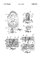
- FIG. 1 is an exploded perspective view showing the elongated rounded latch groove formed in the bottom surface of the cam slide and the lock positioned to be press fit into the circular bore formed through the core retaining plate;
- FIG. 2 is a side elevation partial sectional view of the lock with a portion cut away to show the spring biased plunger
- FIG. 3 is a bottom plan view of the lock taken along line 3--3 of FIG. 2;
- FIG. 4 is a partial side elevation sectional view showing the slide retainer of the present invention in a closed mold where the cam slide is positioned to engage the molded part, and the elongated rounded plunger head of the lock is spaced from the elongated rounded latch groove in the cam slide;
- FIG. 5 is a partial side elevation sectional view showing the slide retainer in an open mold where the cam slide is moved to the left out of engagement with the molded part, and the elongated rounded plunger head of the lock engages the elongated rounded latch groove in the cam slide to hold the cam slide in the retracted position.
- FIG. 1 shows the slide retainer (10) of the present invention as used in a conventional injection mold.
- the mold includes a cam slide (20) having a bottom surface (22) movable in a linear path along the top surface (32) of the core retaining plate (30).
- the cam slide (20) has an elongated rounded latch groove (24) formed in the bottom surface (22).
- the groove (24) is disposed transverse to the linear path of movement of the cam slide (20) as indicated by the directional arrow.
- a circular bore (34) extends through the core retaining plate (30) perpendicular to the top surface (32).
- a counterbore forms a shoulder (36) below the top surface (32) and a flat key section (38) is formed on one side of the counterbore.
- the lock (40) has a circular body portion (42), an enlarged lip section (44), and a flat key section (46) formed on one side of the lip section (44).
- a plunger (48) having an elongated rounded plunger head (50) is received in a cavity formed in the body portion (42).
- a spring (52) is held within the cavity by a threaded plug (54) and biases the plunger head (50) to extend up through an opening (43) in the top of the body portion (42).
- the circular body portion (42) of the lock (40) is matingly received within the circular bore (34) of the core retaining plate (30).
- the slide retainer (10) is used in a mold (80) that includes a heel block (82) secured by a bolt (84) to the exterior plate (86) and the cavity retaining plate (88).
- the heel block (82) contacts the outer section of the cam slide (20) and an angle pin (90) is received in an opening (92) forcing the cam slide (20) to move along the top surface (32) of the core retaining plate (30) into engagement with the molded part (94).
- the elongated rounded latch groove (24) is formed in the bottom surface (22) of the cam slide (20), and the circular bore (34), counterbore, and flattened key section (38) are formed in the core retaining plate (30) as shown in FIG. 1.
- the lock (40) is inserted and press fit into the circular bore (34) so that the circular body portion (42) matingly engages the circular bore (34), the lip (44) engages the shoulder (36), and the flat key section (46) engages the key section (38) of the counterbore.
Landscapes
- Engineering & Computer Science (AREA)
- Manufacturing & Machinery (AREA)
- Mechanical Engineering (AREA)
- Moulds For Moulding Plastics Or The Like (AREA)
Abstract
Description
Claims (6)
Priority Applications (1)
| Application Number | Priority Date | Filing Date | Title |
|---|---|---|---|
| US08/144,420 US5397226A (en) | 1993-11-02 | 1993-11-02 | Slide retainer for injection molds |
Applications Claiming Priority (1)
| Application Number | Priority Date | Filing Date | Title |
|---|---|---|---|
| US08/144,420 US5397226A (en) | 1993-11-02 | 1993-11-02 | Slide retainer for injection molds |
Publications (1)
| Publication Number | Publication Date |
|---|---|
| US5397226A true US5397226A (en) | 1995-03-14 |
Family
ID=22508513
Family Applications (1)
| Application Number | Title | Priority Date | Filing Date |
|---|---|---|---|
| US08/144,420 Expired - Lifetime US5397226A (en) | 1993-11-02 | 1993-11-02 | Slide retainer for injection molds |
Country Status (1)
| Country | Link |
|---|---|
| US (1) | US5397226A (en) |
Cited By (31)
| Publication number | Priority date | Publication date | Assignee | Title |
|---|---|---|---|---|
| EP0695619A1 (en) * | 1994-07-28 | 1996-02-07 | Strack Norma GmbH | Injection mould |
| US5584470A (en) * | 1994-04-28 | 1996-12-17 | Krauss-Maffei Aktiengesellschaft | Method and apparatus for injection molding a hollow-wall container |
| US5587189A (en) * | 1994-10-19 | 1996-12-24 | Wako Plastics Industries Co., Ltd. | Molding device for register of synthetic resin |
| US6126429A (en) * | 1998-06-02 | 2000-10-03 | Burger Engineering, Inc. | Combination slide retainer and position sensing switch for injection molds |
| WO2001032393A1 (en) * | 1999-11-04 | 2001-05-10 | D-M-E Company | Slide retainer for an injection mold |
| EP0968079A4 (en) * | 1997-03-10 | 2001-09-12 | Progressive Components Interna | Molding side-action mechanism and method |
| US6319447B1 (en) | 1999-04-09 | 2001-11-20 | The Boeing Company | Resin transfer molding process |
| EP1107856A4 (en) * | 1999-01-11 | 2002-06-12 | Dme Co | Mold core positioning device |
| US6537053B1 (en) | 2000-01-28 | 2003-03-25 | Plastic Moldings Company, Llc | Modular molding system, and modules for use therewith |
| US6589044B2 (en) * | 2000-05-23 | 2003-07-08 | Alberto Navarra Pruna | Plastic injection mold slide retainer |
| US20050098295A1 (en) * | 2002-09-26 | 2005-05-12 | Dubay Richard L. | Universal slide assembly for molding and casting systems |
| ES2244286A1 (en) * | 2003-07-11 | 2005-12-01 | Comercial De Utiles Y Moldes, S.A. | Retention device for injection molds moves extractor vertically with opening and closing movement of mold |
| US20060013919A1 (en) * | 2004-07-16 | 2006-01-19 | Cerniglia Anthony J | Slide retaining device and method of installation |
| US20060034973A1 (en) * | 2002-11-05 | 2006-02-16 | Hoogland Hendricus A | Apparatus and method for manufacturing holders, in particular crates |
| US20070281051A1 (en) * | 2006-05-31 | 2007-12-06 | Cerniglia Anthony J | Angle pin roller guide |
| US20080236221A1 (en) * | 2007-03-26 | 2008-10-02 | Chih-Yu Chen | Slide having a fixing mechanism of a slide insert |
| US20080276744A1 (en) * | 2007-05-10 | 2008-11-13 | Chih-Yu Chen | Side core-pulling mechanism of mold |
| US7481648B1 (en) * | 2007-11-16 | 2009-01-27 | Cheng Uei Precision Industry Co., Ltd. | Side mold working mechanism |
| US7614873B1 (en) | 2006-11-29 | 2009-11-10 | Custom Products Enterprises, Inc. | Mold base hold retainer |
| US7963759B1 (en) | 2006-11-29 | 2011-06-21 | Custom Products Enterprises, Inc. | Mold base hold retainer and method of using |
| ITBS20100028A1 (en) * | 2010-02-16 | 2011-08-17 | Ermanno Balzi | SLIDING PLATE AND SUPPORT FOR MOLDS COURSE AND MOLD INCLUDING THAT PLATE |
| US20120076887A1 (en) * | 2010-09-27 | 2012-03-29 | Cheng Uei Precision Industry Co., Ltd. | Mould having core-pulling mechanism |
| US20120088004A1 (en) * | 2010-10-06 | 2012-04-12 | Cheng Uei Precision Industry Co., Ltd. | Mold with sliders |
| US20120251656A1 (en) * | 2011-03-31 | 2012-10-04 | Cheng Uei Precision Industry Co., Ltd. | Injection mold |
| US8349240B2 (en) | 2011-03-25 | 2013-01-08 | Honda Motor Co., Ltd. | Hidden parting line mold and hidden parting line molding technique using associated part removal device |
| CN103008607A (en) * | 2012-12-04 | 2013-04-03 | 宁波勋辉电器有限公司 | A sliding block limit structure of a die-casting mold |
| US20140106022A1 (en) * | 2011-06-01 | 2014-04-17 | Comercial De Utiles Moldes, S.A. | Compact slide rail for injection molds |
| CN107399055A (en) * | 2017-09-19 | 2017-11-28 | 歌尔股份有限公司 | Core-pulling device |
| WO2018233742A1 (en) * | 2017-06-22 | 2018-12-27 | Stack Mold Plus Ug | DEVICE FOR FASTENING AND / OR RELEASING INJECTION MOLDS, MEDIUM AND METHOD |
| US10226886B2 (en) * | 2015-01-27 | 2019-03-12 | Samsung Electronics Co., Ltd. | Slim injection molding apparatus |
| CN112140484A (en) * | 2019-06-28 | 2020-12-29 | 汉达精密电子(昆山)有限公司 | Slide block delay mechanism and mold |
Citations (8)
| Publication number | Priority date | Publication date | Assignee | Title |
|---|---|---|---|---|
| US3509603A (en) * | 1967-01-09 | 1970-05-05 | Globe Union Inc | Apparatus for fabricating battery cases |
| US4179254A (en) * | 1978-09-26 | 1979-12-18 | Husky Injection Molding Systems Inc. | Injection mold with floating stripper ring |
| US4452420A (en) * | 1982-09-30 | 1984-06-05 | Lynn Lundquist | Compensating core pin for plastic injection molds |
| US4515342A (en) * | 1984-04-06 | 1985-05-07 | Borislav Boskovic | Slide retainer |
| JPS62240522A (en) * | 1986-04-11 | 1987-10-21 | Hitachi Lighting Ltd | Molding for injection mold |
| US4765585A (en) * | 1987-02-27 | 1988-08-23 | Superior Die Set Corporation | Slide retainer for injection molds |
| US5114655A (en) * | 1989-08-17 | 1992-05-19 | Cole Machine & Mfg. Co. | Method and apparatus for injection molding |
| US5234329A (en) * | 1992-10-02 | 1993-08-10 | Vandenberg Leo A | Angle pin assembly |
-
1993
- 1993-11-02 US US08/144,420 patent/US5397226A/en not_active Expired - Lifetime
Patent Citations (8)
| Publication number | Priority date | Publication date | Assignee | Title |
|---|---|---|---|---|
| US3509603A (en) * | 1967-01-09 | 1970-05-05 | Globe Union Inc | Apparatus for fabricating battery cases |
| US4179254A (en) * | 1978-09-26 | 1979-12-18 | Husky Injection Molding Systems Inc. | Injection mold with floating stripper ring |
| US4452420A (en) * | 1982-09-30 | 1984-06-05 | Lynn Lundquist | Compensating core pin for plastic injection molds |
| US4515342A (en) * | 1984-04-06 | 1985-05-07 | Borislav Boskovic | Slide retainer |
| JPS62240522A (en) * | 1986-04-11 | 1987-10-21 | Hitachi Lighting Ltd | Molding for injection mold |
| US4765585A (en) * | 1987-02-27 | 1988-08-23 | Superior Die Set Corporation | Slide retainer for injection molds |
| US5114655A (en) * | 1989-08-17 | 1992-05-19 | Cole Machine & Mfg. Co. | Method and apparatus for injection molding |
| US5234329A (en) * | 1992-10-02 | 1993-08-10 | Vandenberg Leo A | Angle pin assembly |
Cited By (46)
| Publication number | Priority date | Publication date | Assignee | Title |
|---|---|---|---|---|
| US5584470A (en) * | 1994-04-28 | 1996-12-17 | Krauss-Maffei Aktiengesellschaft | Method and apparatus for injection molding a hollow-wall container |
| EP0695619A1 (en) * | 1994-07-28 | 1996-02-07 | Strack Norma GmbH | Injection mould |
| US5587189A (en) * | 1994-10-19 | 1996-12-24 | Wako Plastics Industries Co., Ltd. | Molding device for register of synthetic resin |
| EP0968079A4 (en) * | 1997-03-10 | 2001-09-12 | Progressive Components Interna | Molding side-action mechanism and method |
| US6126429A (en) * | 1998-06-02 | 2000-10-03 | Burger Engineering, Inc. | Combination slide retainer and position sensing switch for injection molds |
| EP1107856A4 (en) * | 1999-01-11 | 2002-06-12 | Dme Co | Mold core positioning device |
| US6319447B1 (en) | 1999-04-09 | 2001-11-20 | The Boeing Company | Resin transfer molding process |
| US6443723B1 (en) * | 1999-11-04 | 2002-09-03 | D-M-E Company | Slide retainer for an injection mold |
| WO2001032393A1 (en) * | 1999-11-04 | 2001-05-10 | D-M-E Company | Slide retainer for an injection mold |
| US6537053B1 (en) | 2000-01-28 | 2003-03-25 | Plastic Moldings Company, Llc | Modular molding system, and modules for use therewith |
| ES2203261B1 (en) * | 2000-05-23 | 2005-06-16 | Alberto Navarra Pruna | RETENTOR FOR SLIDES OF PLASTIC INJECTION MOLDS. |
| US6589044B2 (en) * | 2000-05-23 | 2003-07-08 | Alberto Navarra Pruna | Plastic injection mold slide retainer |
| ES2203261A1 (en) * | 2000-05-23 | 2004-04-01 | Alberto Navarra Pruna | Plastic injection mould slide retainer |
| US20050098295A1 (en) * | 2002-09-26 | 2005-05-12 | Dubay Richard L. | Universal slide assembly for molding and casting systems |
| US20060034973A1 (en) * | 2002-11-05 | 2006-02-16 | Hoogland Hendricus A | Apparatus and method for manufacturing holders, in particular crates |
| ES2244286A1 (en) * | 2003-07-11 | 2005-12-01 | Comercial De Utiles Y Moldes, S.A. | Retention device for injection molds moves extractor vertically with opening and closing movement of mold |
| ES2244286B1 (en) * | 2003-07-11 | 2007-06-16 | Comercial De Utiles Y Moldes, S.A. | RETAINER AND PUNCHING DEVICE FOR INJECTION MOLDS. |
| US20060013919A1 (en) * | 2004-07-16 | 2006-01-19 | Cerniglia Anthony J | Slide retaining device and method of installation |
| WO2006019504A3 (en) * | 2004-07-16 | 2006-11-23 | Anthony J Cerniglia | Slide retaining device and method of installation |
| US7229269B2 (en) * | 2004-07-16 | 2007-06-12 | Progressive Components International Corporation | Slide retaining device and method of installation |
| US20080085337A1 (en) * | 2004-07-16 | 2008-04-10 | Cerniglia Anthony J | Retaining device |
| US7431581B2 (en) * | 2004-07-16 | 2008-10-07 | Cerniglia Anthony J | Retaining device |
| US20070281051A1 (en) * | 2006-05-31 | 2007-12-06 | Cerniglia Anthony J | Angle pin roller guide |
| US7614873B1 (en) | 2006-11-29 | 2009-11-10 | Custom Products Enterprises, Inc. | Mold base hold retainer |
| US7963759B1 (en) | 2006-11-29 | 2011-06-21 | Custom Products Enterprises, Inc. | Mold base hold retainer and method of using |
| US20080236221A1 (en) * | 2007-03-26 | 2008-10-02 | Chih-Yu Chen | Slide having a fixing mechanism of a slide insert |
| US7677878B2 (en) * | 2007-03-26 | 2010-03-16 | Cheng Uei Precision Industry Co., Ltd. | Slide having a fixing mechanism of a slide insert |
| US20080276744A1 (en) * | 2007-05-10 | 2008-11-13 | Chih-Yu Chen | Side core-pulling mechanism of mold |
| US7549856B2 (en) * | 2007-05-10 | 2009-06-23 | Cheng Uei Precision Industry Co., Ltd. | Side core-pulling mechanism of mold |
| US7481648B1 (en) * | 2007-11-16 | 2009-01-27 | Cheng Uei Precision Industry Co., Ltd. | Side mold working mechanism |
| ITBS20100028A1 (en) * | 2010-02-16 | 2011-08-17 | Ermanno Balzi | SLIDING PLATE AND SUPPORT FOR MOLDS COURSE AND MOLD INCLUDING THAT PLATE |
| US20120076887A1 (en) * | 2010-09-27 | 2012-03-29 | Cheng Uei Precision Industry Co., Ltd. | Mould having core-pulling mechanism |
| US20120088004A1 (en) * | 2010-10-06 | 2012-04-12 | Cheng Uei Precision Industry Co., Ltd. | Mold with sliders |
| US8342838B2 (en) * | 2010-10-06 | 2013-01-01 | Cheng Uei Precision Industry Co., Ltd. | Mold with sliders |
| US8349240B2 (en) | 2011-03-25 | 2013-01-08 | Honda Motor Co., Ltd. | Hidden parting line mold and hidden parting line molding technique using associated part removal device |
| US20120251656A1 (en) * | 2011-03-31 | 2012-10-04 | Cheng Uei Precision Industry Co., Ltd. | Injection mold |
| US9017062B2 (en) * | 2011-06-01 | 2015-04-28 | Alberto Navarra Pruna | Compact slide rail for injection molds |
| US20140106022A1 (en) * | 2011-06-01 | 2014-04-17 | Comercial De Utiles Moldes, S.A. | Compact slide rail for injection molds |
| CN103008607A (en) * | 2012-12-04 | 2013-04-03 | 宁波勋辉电器有限公司 | A sliding block limit structure of a die-casting mold |
| US10226886B2 (en) * | 2015-01-27 | 2019-03-12 | Samsung Electronics Co., Ltd. | Slim injection molding apparatus |
| WO2018233742A1 (en) * | 2017-06-22 | 2018-12-27 | Stack Mold Plus Ug | DEVICE FOR FASTENING AND / OR RELEASING INJECTION MOLDS, MEDIUM AND METHOD |
| US11285647B2 (en) | 2017-06-22 | 2022-03-29 | Stack Mold Plus UG (haftungsbeschränkt) | Device for securing and/or releasing injection moulds, means and method |
| CN107399055A (en) * | 2017-09-19 | 2017-11-28 | 歌尔股份有限公司 | Core-pulling device |
| CN107399055B (en) * | 2017-09-19 | 2019-05-17 | 歌尔股份有限公司 | Core-pulling device |
| CN112140484A (en) * | 2019-06-28 | 2020-12-29 | 汉达精密电子(昆山)有限公司 | Slide block delay mechanism and mold |
| CN112140484B (en) * | 2019-06-28 | 2022-07-15 | 汉达精密电子(昆山)有限公司 | A sliding block delay mechanism and mold |
Similar Documents
| Publication | Publication Date | Title |
|---|---|---|
| US5397226A (en) | Slide retainer for injection molds | |
| US5234329A (en) | Angle pin assembly | |
| US6443723B1 (en) | Slide retainer for an injection mold | |
| US4452420A (en) | Compensating core pin for plastic injection molds | |
| US4472128A (en) | Quick change locator clamp assembly for plastic molding machine | |
| US4765585A (en) | Slide retainer for injection molds | |
| US4920774A (en) | Self-aligning re-keyable pin tumbler cabinet door lock | |
| US6491513B1 (en) | Internal core lifter and a mold incorporating the same | |
| US5387096A (en) | Removable insert for casting molds, and casting mold for producing molded parts | |
| US5407344A (en) | Single direction cam for insert molding machine | |
| CA2408813C (en) | Interchangeable mold insert system | |
| US6120279A (en) | Mold insert positioning system | |
| CA2014120A1 (en) | Valve assembly and locking means therefor | |
| US5494435A (en) | Positive internal latch lock for an injection mold | |
| CA2426046C (en) | Replaceable insert for mold lock | |
| US5208053A (en) | Runner shut-off for an injection molding system | |
| US4889311A (en) | Molding apparatus with improved ejector pin | |
| US5474438A (en) | Adjustable back plate for a mold | |
| US4386868A (en) | Leader pin locking device | |
| US5451156A (en) | Molding ejector device for interchangeable molds | |
| US3930778A (en) | Molding ejector device for interchangeable molds | |
| US4817402A (en) | Locking apparatus | |
| US9770858B1 (en) | Mold interlocks | |
| US4699168A (en) | Theft-resistant valve | |
| US6120275A (en) | Mold for use in a gas-assisted injection molding system and gas pin assembly for use therein |
Legal Events
| Date | Code | Title | Description |
|---|---|---|---|
| AS | Assignment |
Owner name: D-M-E COMPANY, MICHIGAN Free format text: ASSIGNMENT OF ASSIGNORS INTEREST;ASSIGNOR:VANDENBERG, LEO A.;REEL/FRAME:007220/0050 Effective date: 19941108 |
|
| AS | Assignment |
Owner name: D-M-E COMPANY, MICHIGAN Free format text: ASSIGNMENT OF ASSIGNORS INTEREST;ASSIGNOR:VANDENBERG, LEO A.;REEL/FRAME:007321/0683 Effective date: 19941108 |
|
| STCF | Information on status: patent grant |
Free format text: PATENTED CASE |
|
| AS | Assignment |
Owner name: D-M-E COMPANY, MICHIGAN Free format text: ASSIGNMENT OF ASSIGNORS INTEREST;ASSIGNOR:FAIRCHILD INDUSTRIES, INC.;REEL/FRAME:007986/0831 Effective date: 19960513 |
|
| REFU | Refund |
Free format text: REFUND - PAYMENT OF MAINTENANCE FEE, 4TH YR, SMALL ENTITY (ORIGINAL EVENT CODE: R283); ENTITY STATUS OF PATENT OWNER: LARGE ENTITY |
|
| FEPP | Fee payment procedure |
Free format text: PAT HLDR NO LONGER CLAIMS SMALL ENT STAT AS INDIV INVENTOR (ORIGINAL EVENT CODE: LSM1); ENTITY STATUS OF PATENT OWNER: LARGE ENTITY |
|
| FPAY | Fee payment |
Year of fee payment: 4 |
|
| FEPP | Fee payment procedure |
Free format text: PAYOR NUMBER ASSIGNED (ORIGINAL EVENT CODE: ASPN); ENTITY STATUS OF PATENT OWNER: LARGE ENTITY |
|
| AS | Assignment |
Owner name: BANKERS TRUST COMPANY, AS ADMINISTRATIVE AGENT, NE Free format text: SECURITY AGREEMENT;ASSIGNORS:VALENITE U.S.A. INC.;MILACRON INC.;TALBOT HOLDINGS, LTD.;AND OTHERS;REEL/FRAME:013110/0122 Effective date: 20011210 |
|
| FPAY | Fee payment |
Year of fee payment: 8 |
|
| REMI | Maintenance fee reminder mailed | ||
| AS | Assignment |
Owner name: CREDIT SUISSE FIRST BOSTON, ACTING THROUGH ITS CAY Free format text: SECURITY INTEREST;ASSIGNOR:D-M-E COMPANY;REEL/FRAME:014438/0362 Effective date: 20040312 |
|
| AS | Assignment |
Owner name: D-M-E COMPANY, OHIO Free format text: RELEASE;ASSIGNOR:DEUTSCHE BANK TRUST COMPANY AMERICAS F/K/A BANKERS TRUST COMPANY);REEL/FRAME:015246/0147 Effective date: 20040312 |
|
| AS | Assignment |
Owner name: JP MORGAN CHASE BANK, NEW YORK Free format text: SECURITY AGREEMENT;ASSIGNORS:UNILOY MILACRON INC.;D-M-E U.S.A. INC.;MILACRON INC.;AND OTHERS;REEL/FRAME:014763/0181 Effective date: 20040610 |
|
| AS | Assignment |
Owner name: U.S. BANK NATIONAL ASSOCIATION, OHIO Free format text: SECURITY INTEREST;ASSIGNOR:D-M-E COMPANY;REEL/FRAME:015494/0212 Effective date: 20040610 |
|
| AS | Assignment |
Owner name: D-M-E COMPANY, MICHIGAN Free format text: RELEASE OF LIEN IN PATENTS;ASSIGNOR:CREIDT SUISSE FIRST BOSTON, ACTING THROUGH ITS CAYMAN ISLANDS BRANCH ONE MADISON AVENUE NEW YORK, NY 10010;REEL/FRAME:014852/0375 Effective date: 20040610 Owner name: D-M-E U.S.A. INC., MICHIGAN Free format text: RELEASE OF LIEN IN PATENTS;ASSIGNOR:CREIDT SUISSE FIRST BOSTON, ACTING THROUGH ITS CAYMAN ISLANDS BRANCH ONE MADISON AVENUE NEW YORK, NY 10010;REEL/FRAME:014852/0375 Effective date: 20040610 Owner name: MILACRON INC., OHIO Free format text: RELEASE OF LIEN IN PATENTS;ASSIGNOR:CREIDT SUISSE FIRST BOSTON, ACTING THROUGH ITS CAYMAN ISLANDS BRANCH ONE MADISON AVENUE NEW YORK, NY 10010;REEL/FRAME:014852/0375 Effective date: 20040610 Owner name: MILACRON INDUSTRIAL PRODUCTS, INC., MICHIGAN Free format text: RELEASE OF LIEN IN PATENTS;ASSIGNOR:CREIDT SUISSE FIRST BOSTON, ACTING THROUGH ITS CAYMAN ISLANDS BRANCH ONE MADISON AVENUE NEW YORK, NY 10010;REEL/FRAME:014852/0375 Effective date: 20040610 Owner name: OAK INTERNATIONAL, INC., MICHIGAN Free format text: RELEASE OF LIEN IN PATENTS;ASSIGNOR:CREIDT SUISSE FIRST BOSTON, ACTING THROUGH ITS CAYMAN ISLANDS BRANCH ONE MADISON AVENUE NEW YORK, NY 10010;REEL/FRAME:014852/0375 Effective date: 20040610 Owner name: UNILOY MILACRON U.S.A. INC., MICHIGAN Free format text: RELEASE OF LIEN IN PATENTS;ASSIGNOR:CREIDT SUISSE FIRST BOSTON, ACTING THROUGH ITS CAYMAN ISLANDS BRANCH ONE MADISON AVENUE NEW YORK, NY 10010;REEL/FRAME:014852/0375 Effective date: 20040610 Owner name: UNILOY MILACRON, INC., MICHIGAN Free format text: RELEASE OF LIEN IN PATENTS;ASSIGNOR:CREIDT SUISSE FIRST BOSTON, ACTING THROUGH ITS CAYMAN ISLANDS BRANCH ONE MADISON AVENUE NEW YORK, NY 10010;REEL/FRAME:014852/0375 Effective date: 20040610 |
|
| FPAY | Fee payment |
Year of fee payment: 12 |
|
| AS | Assignment |
Owner name: GENERAL ELECTRIC CAPITAL CORPORATION, AS AGENT, CO Free format text: SECURITY AGREEMENT;ASSIGNORS:MILACRON INC.;D-M-E U.S.A. INC.;MILACRON INDUSTRIAL PRODUCTS, INC.;AND OTHERS;REEL/FRAME:018688/0070 Effective date: 20061219 Owner name: GENERAL ELECTRIC CAPITAL CORPORATION, AS AGENT,CON Free format text: SECURITY AGREEMENT;ASSIGNORS:MILACRON INC.;D-M-E U.S.A. INC.;MILACRON INDUSTRIAL PRODUCTS, INC.;AND OTHERS;REEL/FRAME:018688/0070 Effective date: 20061219 Owner name: UNILOY MILACRON INC.,MICHIGAN Free format text: RELEASE BY SECURED PARTY;ASSIGNOR:JPMORGAN CHASE BANK, N.A.;REEL/FRAME:018688/0001 Effective date: 20061219 Owner name: OAK INTERNATIONAL, INC.,MICHIGAN Free format text: RELEASE BY SECURED PARTY;ASSIGNOR:JPMORGAN CHASE BANK, N.A.;REEL/FRAME:018688/0001 Effective date: 20061219 Owner name: MILACRON INDUSTRIAL PRODUCTS, INC.,MICHIGAN Free format text: RELEASE BY SECURED PARTY;ASSIGNOR:JPMORGAN CHASE BANK, N.A.;REEL/FRAME:018688/0001 Effective date: 20061219 Owner name: D-M-E COMPANY,MICHIGAN Free format text: RELEASE BY SECURED PARTY;ASSIGNOR:JPMORGAN CHASE BANK, N.A.;REEL/FRAME:018688/0001 Effective date: 20061219 Owner name: MILACRON INC.,OHIO Free format text: RELEASE BY SECURED PARTY;ASSIGNOR:JPMORGAN CHASE BANK, N.A.;REEL/FRAME:018688/0001 Effective date: 20061219 Owner name: D-M-E U.S.A. INC,MICHIGAN Free format text: RELEASE BY SECURED PARTY;ASSIGNOR:JPMORGAN CHASE BANK, N.A.;REEL/FRAME:018688/0001 Effective date: 20061219 Owner name: UNILOY MILACRON U.S.A. INC.,MICHIGAN Free format text: RELEASE BY SECURED PARTY;ASSIGNOR:JPMORGAN CHASE BANK, N.A.;REEL/FRAME:018688/0001 Effective date: 20061219 Owner name: MILACRON INC., OHIO Free format text: RELEASE BY SECURED PARTY;ASSIGNOR:JPMORGAN CHASE BANK, N.A.;REEL/FRAME:018688/0001 Effective date: 20061219 Owner name: D-M-E U.S.A. INC, MICHIGAN Free format text: RELEASE BY SECURED PARTY;ASSIGNOR:JPMORGAN CHASE BANK, N.A.;REEL/FRAME:018688/0001 Effective date: 20061219 Owner name: MILACRON INDUSTRIAL PRODUCTS, INC., MICHIGAN Free format text: RELEASE BY SECURED PARTY;ASSIGNOR:JPMORGAN CHASE BANK, N.A.;REEL/FRAME:018688/0001 Effective date: 20061219 Owner name: UNILOY MILACRON INC., MICHIGAN Free format text: RELEASE BY SECURED PARTY;ASSIGNOR:JPMORGAN CHASE BANK, N.A.;REEL/FRAME:018688/0001 Effective date: 20061219 Owner name: UNILOY MILACRON U.S.A. INC., MICHIGAN Free format text: RELEASE BY SECURED PARTY;ASSIGNOR:JPMORGAN CHASE BANK, N.A.;REEL/FRAME:018688/0001 Effective date: 20061219 Owner name: D-M-E COMPANY, MICHIGAN Free format text: RELEASE BY SECURED PARTY;ASSIGNOR:JPMORGAN CHASE BANK, N.A.;REEL/FRAME:018688/0001 Effective date: 20061219 Owner name: OAK INTERNATIONAL, INC., MICHIGAN Free format text: RELEASE BY SECURED PARTY;ASSIGNOR:JPMORGAN CHASE BANK, N.A.;REEL/FRAME:018688/0001 Effective date: 20061219 |
|
| AS | Assignment |
Owner name: GENERAL ELECTRIC CAPITAL CORPORATION, AS AGENT, CO Free format text: SECURITY AGREEMENT;ASSIGNORS:MILACRON INC;CIMCOOL INDUSTRIAL PRODUCTS INC.;MILACRON MARKETING COMPANY;AND OTHERS;REEL/FRAME:022427/0080 Effective date: 20090311 Owner name: GENERAL ELECTRIC CAPITAL CORPORATION, AS AGENT,CON Free format text: SECURITY AGREEMENT;ASSIGNORS:MILACRON INC;CIMCOOL INDUSTRIAL PRODUCTS INC.;MILACRON MARKETING COMPANY;AND OTHERS;REEL/FRAME:022427/0080 Effective date: 20090311 |
|
| AS | Assignment |
Owner name: D-M-E COMPANY, INC., MICHIGAN Free format text: RELEASE BY SECURED PARTY;ASSIGNOR:U.S. BANK NATIONAL ASSOCIATION, AS TRUSTEE AND COLLATERAL AGENT;REEL/FRAME:023134/0432 Effective date: 20090821 Owner name: D-M-E U.S.A. INC., MICHIGAN Free format text: RELEASE BY SECURED PARTY;ASSIGNOR:U.S. BANK NATIONAL ASSOCIATION, AS TRUSTEE AND COLLATERAL AGENT;REEL/FRAME:023134/0432 Effective date: 20090821 Owner name: MILACRON INC., OHIO Free format text: RELEASE BY SECURED PARTY;ASSIGNOR:U.S. BANK NATIONAL ASSOCIATION, AS TRUSTEE AND COLLATERAL AGENT;REEL/FRAME:023134/0432 Effective date: 20090821 Owner name: MILACRON INDUSTRIAL PRODUCTS INC., MICHIGAN Free format text: RELEASE BY SECURED PARTY;ASSIGNOR:U.S. BANK NATIONAL ASSOCIATION, AS TRUSTEE AND COLLATERAL AGENT;REEL/FRAME:023134/0432 Effective date: 20090821 Owner name: OAK INTERNATIONAL, INC., MICHIGAN Free format text: RELEASE BY SECURED PARTY;ASSIGNOR:U.S. BANK NATIONAL ASSOCIATION, AS TRUSTEE AND COLLATERAL AGENT;REEL/FRAME:023134/0432 Effective date: 20090821 Owner name: UNILOY MILACRON INC., MICHIGAN Free format text: RELEASE BY SECURED PARTY;ASSIGNOR:U.S. BANK NATIONAL ASSOCIATION, AS TRUSTEE AND COLLATERAL AGENT;REEL/FRAME:023134/0432 Effective date: 20090821 Owner name: UNILOY MILACRON U.S.A. INC., MICHIGAN Free format text: RELEASE BY SECURED PARTY;ASSIGNOR:U.S. BANK NATIONAL ASSOCIATION, AS TRUSTEE AND COLLATERAL AGENT;REEL/FRAME:023134/0432 Effective date: 20090821 Owner name: D-M-E COMPANY, INC.,MICHIGAN Free format text: RELEASE BY SECURED PARTY;ASSIGNOR:U.S. BANK NATIONAL ASSOCIATION, AS TRUSTEE AND COLLATERAL AGENT;REEL/FRAME:023134/0432 Effective date: 20090821 Owner name: D-M-E U.S.A. INC.,MICHIGAN Free format text: RELEASE BY SECURED PARTY;ASSIGNOR:U.S. BANK NATIONAL ASSOCIATION, AS TRUSTEE AND COLLATERAL AGENT;REEL/FRAME:023134/0432 Effective date: 20090821 Owner name: MILACRON INC.,OHIO Free format text: RELEASE BY SECURED PARTY;ASSIGNOR:U.S. BANK NATIONAL ASSOCIATION, AS TRUSTEE AND COLLATERAL AGENT;REEL/FRAME:023134/0432 Effective date: 20090821 Owner name: MILACRON INDUSTRIAL PRODUCTS INC.,MICHIGAN Free format text: RELEASE BY SECURED PARTY;ASSIGNOR:U.S. BANK NATIONAL ASSOCIATION, AS TRUSTEE AND COLLATERAL AGENT;REEL/FRAME:023134/0432 Effective date: 20090821 Owner name: OAK INTERNATIONAL, INC.,MICHIGAN Free format text: RELEASE BY SECURED PARTY;ASSIGNOR:U.S. BANK NATIONAL ASSOCIATION, AS TRUSTEE AND COLLATERAL AGENT;REEL/FRAME:023134/0432 Effective date: 20090821 Owner name: UNILOY MILACRON INC.,MICHIGAN Free format text: RELEASE BY SECURED PARTY;ASSIGNOR:U.S. BANK NATIONAL ASSOCIATION, AS TRUSTEE AND COLLATERAL AGENT;REEL/FRAME:023134/0432 Effective date: 20090821 Owner name: UNILOY MILACRON U.S.A. INC.,MICHIGAN Free format text: RELEASE BY SECURED PARTY;ASSIGNOR:U.S. BANK NATIONAL ASSOCIATION, AS TRUSTEE AND COLLATERAL AGENT;REEL/FRAME:023134/0432 Effective date: 20090821 |
|
| AS | Assignment |
Owner name: WELLS FARGO FOOTHILL, LLC, AS AGENT, GEORGIA Free format text: SECURITY AGREEMENT;ASSIGNORS:MILACRON LLC;DME COMPANY LLC;REEL/FRAME:023134/0669 Effective date: 20090821 Owner name: WELLS FARGO FOOTHILL, LLC, AS AGENT,GEORGIA Free format text: SECURITY AGREEMENT;ASSIGNORS:MILACRON LLC;DME COMPANY LLC;REEL/FRAME:023134/0669 Effective date: 20090821 |
|
| AS | Assignment |
Owner name: DME COMPANY LLC, MICHIGAN Free format text: ASSIGNMENT OF ASSIGNORS INTEREST;ASSIGNOR:D-M-E COMPANY;REEL/FRAME:023163/0620 Effective date: 20090818 Owner name: DME COMPANY LLC,MICHIGAN Free format text: ASSIGNMENT OF ASSIGNORS INTEREST;ASSIGNOR:D-M-E COMPANY;REEL/FRAME:023163/0620 Effective date: 20090818 |
|
| AS | Assignment |
Owner name: MILACRON INC., OHIO Free format text: RELEASE BY SECURED PARTY;ASSIGNOR:GENERAL ELECTRIC CAPITAL CORPORATION, AS AGENT;REEL/FRAME:023180/0690 Effective date: 20090821 Owner name: MILACRON MARKETING COMPANY, OHIO Free format text: RELEASE BY SECURED PARTY;ASSIGNOR:GENERAL ELECTRIC CAPITAL CORPORATION, AS AGENT;REEL/FRAME:023180/0690 Effective date: 20090821 Owner name: MILACRON PLASTICS TECHNOLOGIES GROUP INC., OHIO Free format text: RELEASE BY SECURED PARTY;ASSIGNOR:GENERAL ELECTRIC CAPITAL CORPORATION, AS AGENT;REEL/FRAME:023180/0690 Effective date: 20090821 Owner name: D-M-E COMPANY, INC., MICHIGAN Free format text: RELEASE BY SECURED PARTY;ASSIGNOR:GENERAL ELECTRIC CAPITAL CORPORATION, AS AGENT;REEL/FRAME:023180/0690 Effective date: 20090821 Owner name: CIMCOOL INDUSTRIAL PRODUCTS INC., OHIO Free format text: RELEASE BY SECURED PARTY;ASSIGNOR:GENERAL ELECTRIC CAPITAL CORPORATION, AS AGENT;REEL/FRAME:023180/0690 Effective date: 20090821 Owner name: MILACRON INC.,OHIO Free format text: RELEASE BY SECURED PARTY;ASSIGNOR:GENERAL ELECTRIC CAPITAL CORPORATION, AS AGENT;REEL/FRAME:023180/0690 Effective date: 20090821 Owner name: MILACRON MARKETING COMPANY,OHIO Free format text: RELEASE BY SECURED PARTY;ASSIGNOR:GENERAL ELECTRIC CAPITAL CORPORATION, AS AGENT;REEL/FRAME:023180/0690 Effective date: 20090821 Owner name: MILACRON PLASTICS TECHNOLOGIES GROUP INC.,OHIO Free format text: RELEASE BY SECURED PARTY;ASSIGNOR:GENERAL ELECTRIC CAPITAL CORPORATION, AS AGENT;REEL/FRAME:023180/0690 Effective date: 20090821 Owner name: D-M-E COMPANY, INC.,MICHIGAN Free format text: RELEASE BY SECURED PARTY;ASSIGNOR:GENERAL ELECTRIC CAPITAL CORPORATION, AS AGENT;REEL/FRAME:023180/0690 Effective date: 20090821 Owner name: CIMCOOL INDUSTRIAL PRODUCTS INC.,OHIO Free format text: RELEASE BY SECURED PARTY;ASSIGNOR:GENERAL ELECTRIC CAPITAL CORPORATION, AS AGENT;REEL/FRAME:023180/0690 Effective date: 20090821 |
|
| AS | Assignment |
Owner name: THE BANK OF NEW YORK MELLON, TEXAS Free format text: SECOND LIEN PATENT SECURITY AGREEMENT;ASSIGNORS:MILACRON LLC;DME COMPANY LLC;REEL/FRAME:023449/0926 Effective date: 20091021 Owner name: THE BANK OF NEW YORK MELLON,TEXAS Free format text: SECOND LIEN PATENT SECURITY AGREEMENT;ASSIGNORS:MILACRON LLC;DME COMPANY LLC;REEL/FRAME:023449/0926 Effective date: 20091021 |
|
| AS | Assignment |
Owner name: DME COMPANY LLC, MICHIGAN Free format text: SECURITY AGREEMENT;ASSIGNOR:THE BANK OF NEW YORK MELLON;REEL/FRAME:026346/0680 Effective date: 20110506 Owner name: BANK OF AMERICA, N.A., AS ADMINISTRATIVE AGENT, IL Free format text: SECURITY AGREEMENT;ASSIGNORS:MILACRON LLC;DME COMPANY LLC;REEL/FRAME:026341/0357 Effective date: 20110506 |
|
| AS | Assignment |
Owner name: DME COMPANY LLC, MICHIGAN Free format text: RELEASE BY SECURED PARTY;ASSIGNOR:WELLS FARGO CAPITAL FINANCE LLC;REEL/FRAME:028129/0027 Effective date: 20120430 |
|
| AS | Assignment |
Owner name: DME COMPANY LLC, MICHIGAN Free format text: PATENT RELEASE;ASSIGNOR:BANK OF AMERICA, N.A., AS ADMINISTRATIVE AGENT;REEL/FRAME:028153/0392 Effective date: 20120430 |
|
| AS | Assignment |
Owner name: U.S. BANK NATIONAL ASSOCIATION, AS NOTES COLLATERA Free format text: SECURITY AGREEMENT;ASSIGNORS:DME COMPANY LLC;MILACRON LLC;REEL/FRAME:028154/0084 Effective date: 20120430 |
|
| AS | Assignment |
Owner name: BANK OF AMERICA, N.A., AS COLLATERAL AGENT, WISCON Free format text: SECURITY AGREEMENT;ASSIGNORS:DME COMPANY LLC;MILACRON LLC;REEL/FRAME:028168/0689 Effective date: 20120430 |
|
| AS | Assignment |
Owner name: U.S. BANK NATIONAL ASSOCIATION, AS NOTES COLLATERA Free format text: SECURITY AGREEMENT;ASSIGNORS:MILACRON LLC;DME COMPANY LLC;REEL/FRAME:030201/0510 Effective date: 20130328 |
|
| AS | Assignment |
Owner name: DME COMPANY LLC, MICHIGAN Free format text: RELEASE OF INTELLECTUAL PROPERTY SECURITY AGREEMENT;ASSIGNOR:U.S. BANK NATIONAL ASSOCIATION;REEL/FRAME:035668/0634 Effective date: 20150514 Owner name: MILACRON LLC, OHIO Free format text: RELEASE OF INTELLECTUAL PROPERTY SECURITY AGREEMENT;ASSIGNOR:U.S. BANK NATIONAL ASSOCIATION;REEL/FRAME:035668/0634 Effective date: 20150514 Owner name: KORTEC, INC., OHIO Free format text: RELEASE OF INTELLECTUAL PROPERTY SECURITY AGREEMENT;ASSIGNOR:U.S. BANK NATIONAL ASSOCIATION;REEL/FRAME:035668/0634 Effective date: 20150514 |
|
| AS | Assignment |
Owner name: DME COMPANY LLC, MICHIGAN Free format text: RELEASE BY SECURED PARTY;ASSIGNOR:BANK OF AMERICA, N.A.;REEL/FRAME:051094/0964 Effective date: 20191121 Owner name: MILACRON LLC, OHIO Free format text: RELEASE BY SECURED PARTY;ASSIGNOR:BANK OF AMERICA, N.A.;REEL/FRAME:051094/0964 Effective date: 20191121 |