US539320A - Band-saw mill - Google Patents
Band-saw mill Download PDFInfo
- Publication number
- US539320A US539320A US539320DA US539320A US 539320 A US539320 A US 539320A US 539320D A US539320D A US 539320DA US 539320 A US539320 A US 539320A
- Authority
- US
- United States
- Prior art keywords
- band
- saw
- pedestal
- mill
- saw mill
- Prior art date
- Legal status (The legal status is an assumption and is not a legal conclusion. Google has not performed a legal analysis and makes no representation as to the accuracy of the status listed.)
- Expired - Lifetime
Links
Images
Classifications
-
- B—PERFORMING OPERATIONS; TRANSPORTING
- B27—WORKING OR PRESERVING WOOD OR SIMILAR MATERIAL; NAILING OR STAPLING MACHINES IN GENERAL
- B27B—SAWS FOR WOOD OR SIMILAR MATERIAL; COMPONENTS OR ACCESSORIES THEREFOR
- B27B13/00—Band or strap sawing machines; Components or equipment therefor
- B27B13/08—Arrangements for stretching the band saw blade
-
- Y—GENERAL TAGGING OF NEW TECHNOLOGICAL DEVELOPMENTS; GENERAL TAGGING OF CROSS-SECTIONAL TECHNOLOGIES SPANNING OVER SEVERAL SECTIONS OF THE IPC; TECHNICAL SUBJECTS COVERED BY FORMER USPC CROSS-REFERENCE ART COLLECTIONS [XRACs] AND DIGESTS
- Y10—TECHNICAL SUBJECTS COVERED BY FORMER USPC
- Y10T—TECHNICAL SUBJECTS COVERED BY FORMER US CLASSIFICATION
- Y10T83/00—Cutting
- Y10T83/707—By endless band or chain knife
- Y10T83/7226—With means to guard the tension
- Y10T83/7239—With means to vary distance between pulley or sprocket axes
-
- Y—GENERAL TAGGING OF NEW TECHNOLOGICAL DEVELOPMENTS; GENERAL TAGGING OF CROSS-SECTIONAL TECHNOLOGIES SPANNING OVER SEVERAL SECTIONS OF THE IPC; TECHNICAL SUBJECTS COVERED BY FORMER USPC CROSS-REFERENCE ART COLLECTIONS [XRACs] AND DIGESTS
- Y10—TECHNICAL SUBJECTS COVERED BY FORMER USPC
- Y10T—TECHNICAL SUBJECTS COVERED BY FORMER US CLASSIFICATION
- Y10T83/00—Cutting
- Y10T83/707—By endless band or chain knife
- Y10T83/7226—With means to guard the tension
- Y10T83/7239—With means to vary distance between pulley or sprocket axes
- Y10T83/7251—Including means to yieldably bias pulley
Definitions
- a TTOHNEYS TnE mam virus 00., mafaumm wunmcnma-mc.
- This invention relates to band saw mills structing the frame as shown, for one set of and consists in certain improvements in the construction thereof, as will fully appear in the following specification and claims.
- the invention relates more particularly to the construction of the frame work and the means for straining the saw.
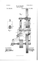
- Figure 1 shows the framework in vertical section and the working parts in elevation.
- Fig. 2 shows a detail construction.
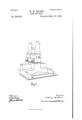
- Fig. 3 shows the framework in perspective with the working parts removed.
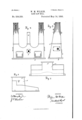
- Fig. 4 shows a side elevation of theupper part of the frame.
- Fig. 5 shows an end view of the same.
- Fig. 6 shows a side view of the base of the frame.
- Fig. 7 show the ends of the base of the frame, liooki3ng from the left of Fig. 6 and the rear of The frame proper consists of but two pieces of cast metal, the base, A, and the top B.
- the base, A has a pedestal,A', to receive the top, B, and the top, B, has two upwardly extending prongs, B B, to receive the upper shaft supports, and a shorter middle prong, B to hold the saw guide fixtures, but these prongs and the pedestal are cast integral with the part to which they belong.
- One side, I), of the top, B, is nearly vertical, 'while the other side is at considerable of an angle. The side,
- the base, A is alike in form at all like points on either side of the pedestal.
- the top, B may set on the pedestal with the vertical face, b, facing either the one side or the other of the pedestal, or, in other words,
- the log-carriage way may be on either'side of the pedestal, A, according to whether the mill is what is called right orleft, and the top, B, maybe fixed to the pedestal with its vertical side, Z2, facing the carriage whether the carriage is on the right or the left of the ped estal.
- the top, B extends over the pedestal in the direction of the-rear of Fig. 3, or the leftof Fig. 6, and which would be toward the front of Fig. 7, and is so shown at the right of Fig. 1, and the lower shafts outer hanger, 0, extends down from the overhanging part.
- the hanger, C is attached to the top piece, B, by bolts and directly below the outer post, B.
- the means for straining the saw are as follows:
- the upper band wheel shaft,E is journaled, as commonly, on thetop of posts, D D, which are telescopically fitted in the posts,'B' B, and are adjusted primarily by screw rods, D, operated by worm wheels, d, worm shaft, (1, and hand wheel, (V.
- the lower ends of the screw rods, D, are pointed and set in bearings on the short ends of L formed levers, G, which are fulcrumed on points, g, and the long ends of the levers, G, are connected by links, g, with arms, h, on a shaft, H, which has an arm, 11, from which hangs a-weight, H on a pendent rod, W, and the seat of the weight, H is on a spring, H (See Fig. 2.)
- the weight, H acting through the leverage described keeps the saw on the wheels F F, under constant strain or tension. of the spring, H is to afford a quick yielding relief to the saw when it is suddenlyimpeded from any cause.
- the spring H will yield and allow an upward movement of the rod, 71 before the inertia of the weight, H can be overcome.
- the points of the rods, D are seated in the bottoms of cups, g formed on The object IOO the levers, G, in which cups a quantity of oil is kept to maintain a sure lubrication. It is desirable that the bearing points of the rods, D, be, as nearly as possible, on a level with the points of the bearings, 9, so that the levers, G, can lift the rods, 1), the necessary distance, which is usually about one fourth of an inch, without pulling the rods, D, sidewise to any objectionable extent.
Landscapes
- Life Sciences & Earth Sciences (AREA)
- Engineering & Computer Science (AREA)
- Mechanical Engineering (AREA)
- Wood Science & Technology (AREA)
- Forests & Forestry (AREA)
- Adornments (AREA)
Description
(No Model.) s Sheets-Sheet 1.
W.. M. WILKIN.
BAND SAW MILL.
No. 539,320. Patented May 14 1895.
(Nd Model.) 3 Sheets-Sheet 2. W. M. WILKIN.
BAND SAW MILL. 7
No. 539,320. Patented May 14, 1895.
l/v i wwooeo gWUM/Ltoz I attovwzwam-x 7 k TN: "on" Ftrzps 00.. wdruumo. wuumofom 0. 1:.
(No Model.)' 3 Sheets-Sheet 3.
. W. M. WILKIN.
BAND SAW MILL.
Patented May 14, 1895.
llllllilll lNVEA/TOH.
A TTOHNEYS TnE mam: virus 00., mafaumm wunmcnma-mc.
U ITED STAT S I PATENT OFFIcE.
WILLIAM M. wrLKIN, OF ERIE; PENNSYLVANIA.
BAND-SAW MILL.
SPECIFICATION forming part Of Letters Patent No. 539,320, dated May 14, 1895.
A lication filed April 26, 1894- $erial N0. 509,088. (No model.)
To all whom it may concern:
Be it known that I, WILLIAM M. WILKIN, a.
in the county of Erie and State of Pennsyl- Vania, have invented certain new and useful Improvements in Band-Saw Mills; and I do hereby declare the following to be a full, clear, and exact description of the invention, such as will enable others skilled in the art to which it appertains to make and use the same.
This invention relates to band saw mills structing the frame as shown, for one set of and consists in certain improvements in the construction thereof, as will fully appear in the following specification and claims.
The invention relates more particularly to the construction of the frame work and the means for straining the saw.
The accompanying drawings illustrate the invention, as follows: a
Figure 1 shows the framework in vertical section and the working parts in elevation. Fig. 2 shows a detail construction. Fig. 3 shows the framework in perspective with the working parts removed. Fig. 4 shows a side elevation of theupper part of the frame. Fig. 5 shows an end view of the same. Fig. 6 shows a side view of the base of the frame. Fig. 7 show the ends of the base of the frame, liooki3ng from the left of Fig. 6 and the rear of The frame proper consists of but two pieces of cast metal, the base, A, and the top B. The base, A, has a pedestal,A', to receive the top, B, and the top, B, has two upwardly extending prongs, B B, to receive the upper shaft supports, and a shorter middle prong, B to hold the saw guide fixtures, but these prongs and the pedestal are cast integral with the part to which they belong. One side, I), of the top, B, is nearly vertical, 'while the other side is at considerable of an angle. The side,
I), faces the log-carriage way, or, in other words, the cutting point of the saw. The base, A, is alike in form at all like points on either side of the pedestal.
The top, B, may set on the pedestal with the vertical face, b, facing either the one side or the other of the pedestal, or, in other words,
' the log-carriage way may be on either'side of the pedestal, A, according to whether the mill is what is called right orleft, and the top, B, maybe fixed to the pedestal with its vertical side, Z2, facing the carriage whether the carriage is on the right or the left of the ped estal. The top, B, extends over the pedestal in the direction of the-rear of Fig. 3, or the leftof Fig. 6, and which would be toward the front of Fig. 7, and is so shown at the right of Fig. 1, and the lower shafts outer hanger, 0, extends down from the overhanging part. The hanger, C, is attached to the top piece, B, by bolts and directly below the outer post, B.
There is considerable advantage in conpatterns serves to build either right or left hand mills, and one kind or the other can be built from a common stock of castings, and there is no difference in the finishingup of parts, for they come together properly in either case, and a mill that is assembled intended for a right hand mill can be taken apart and re-assembled as a left hand mill. To do this the only change necessary would be to take out the upper shaft, loosen the hanger, 0, turn the part, B, around end for end, and put the removed parts back into place (and change the position of the saw guide, which is not shown, and some other minor parts).
. The means for straining the saw are as follows: The upper band wheel shaft,E, is journaled, as commonly, on thetop of posts, D D, which are telescopically fitted in the posts,'B' B, and are adjusted primarily by screw rods, D, operated by worm wheels, d, worm shaft, (1, and hand wheel, (V. The lower ends of the screw rods, D, are pointed and set in bearings on the short ends of L formed levers, G, which are fulcrumed on points, g, and the long ends of the levers, G, are connected by links, g, with arms, h, on a shaft, H, which has an arm, 11, from which hangs a-weight, H on a pendent rod, W, and the seat of the weight, H is on a spring, H (See Fig. 2.) The weight, H acting through the leverage described keeps the saw on the wheels F F, under constant strain or tension. of the spring, H is to afford a quick yielding relief to the saw when it is suddenlyimpeded from any cause. The spring H will yield and allow an upward movement of the rod, 71 before the inertia of the weight, H can be overcome. The points of the rods, D, are seated in the bottoms of cups, g formed on The object IOO the levers, G, in which cups a quantity of oil is kept to maintain a sure lubrication. It is desirable that the bearing points of the rods, D, be, as nearly as possible, on a level with the points of the bearings, 9, so that the levers, G, can lift the rods, 1), the necessary distance, which is usually about one fourth of an inch, without pulling the rods, D, sidewise to any objectionable extent.
What I claim as new is- 1. In a band saw-mill, the combination in the frame work thereof, of a base, A, having a pedestal, A, formed integral therewith; a top part, B, having the posts, B 13, formed integral therewith, and made attachable to said pedestal with its face side, 11, facing either to the right or theleft as required; and a hanger, (J, for the outer end of the lower band-wheel-shaft, attached to the end of the WILLIAM M. WILKIN.
\Vitnesses:
JNo. K. IIALLOCK, C. B. HAYES.
Publications (1)
| Publication Number | Publication Date |
|---|---|
| US539320A true US539320A (en) | 1895-05-14 |
Family
ID=2608080
Family Applications (1)
| Application Number | Title | Priority Date | Filing Date |
|---|---|---|---|
| US539320D Expired - Lifetime US539320A (en) | Band-saw mill |
Country Status (1)
| Country | Link |
|---|---|
| US (1) | US539320A (en) |
-
0
- US US539320D patent/US539320A/en not_active Expired - Lifetime
Similar Documents
| Publication | Publication Date | Title |
|---|---|---|
| US539320A (en) | Band-saw mill | |
| US285407A (en) | aretschel | |
| US532663A (en) | hanson | |
| US451106A (en) | Band-saw mill | |
| US381466A (en) | Halp to lewis w | |
| US428785A (en) | Band-saw mill | |
| US164391A (en) | Improvement in metal-shearing machines | |
| US63614A (en) | Improvement in head-blocks foe saw-mills | |
| US362410A (en) | Band-saw mill | |
| US658166A (en) | Band-saw mill. | |
| US780425A (en) | Band-saw mill. | |
| US640502A (en) | Yielding guide for band-saw mills. | |
| US349356A (en) | Circular-saw mill | |
| US960472A (en) | Gang-saw mill. | |
| US69041A (en) | Improvement in hangees | |
| US545000A (en) | thomas | |
| US131669A (en) | Improvement in scroll-sawing machines | |
| US477299A (en) | Band-sawmill | |
| US578625A (en) | Albert c | |
| US437490A (en) | Dempsey b | |
| US53804A (en) | edmonds | |
| US94668A (en) | Improvement in sawingmmachine | |
| US42780A (en) | Improvement in wood-splitting machines | |
| US156035A (en) | Improvement in paper-cutting machines | |
| US371211A (en) | n naudey |