US5391061A - Hermetic terminal cover and compressor incorporating same - Google Patents
Hermetic terminal cover and compressor incorporating same Download PDFInfo
- Publication number
- US5391061A US5391061A US08/030,978 US3097893A US5391061A US 5391061 A US5391061 A US 5391061A US 3097893 A US3097893 A US 3097893A US 5391061 A US5391061 A US 5391061A
- Authority
- US
- United States
- Prior art keywords
- terminal
- hermetic
- cover
- hermetic terminal
- caps
- Prior art date
- Legal status (The legal status is an assumption and is not a legal conclusion. Google has not performed a legal analysis and makes no representation as to the accuracy of the status listed.)
- Expired - Lifetime
Links
Images


Classifications
-
- H—ELECTRICITY
- H01—ELECTRIC ELEMENTS
- H01R—ELECTRICALLY-CONDUCTIVE CONNECTIONS; STRUCTURAL ASSOCIATIONS OF A PLURALITY OF MUTUALLY-INSULATED ELECTRICAL CONNECTING ELEMENTS; COUPLING DEVICES; CURRENT COLLECTORS
- H01R13/00—Details of coupling devices of the kinds covered by groups H01R12/70 or H01R24/00 - H01R33/00
- H01R13/46—Bases; Cases
- H01R13/52—Dustproof, splashproof, drip-proof, waterproof, or flameproof cases
- H01R13/5202—Sealing means between parts of housing or between housing part and a wall, e.g. sealing rings
-
- H—ELECTRICITY
- H01—ELECTRIC ELEMENTS
- H01R—ELECTRICALLY-CONDUCTIVE CONNECTIONS; STRUCTURAL ASSOCIATIONS OF A PLURALITY OF MUTUALLY-INSULATED ELECTRICAL CONNECTING ELEMENTS; COUPLING DEVICES; CURRENT COLLECTORS
- H01R13/00—Details of coupling devices of the kinds covered by groups H01R12/70 or H01R24/00 - H01R33/00
- H01R13/46—Bases; Cases
- H01R13/52—Dustproof, splashproof, drip-proof, waterproof, or flameproof cases
- H01R13/521—Sealing between contact members and housing, e.g. sealing insert
-
- Y—GENERAL TAGGING OF NEW TECHNOLOGICAL DEVELOPMENTS; GENERAL TAGGING OF CROSS-SECTIONAL TECHNOLOGIES SPANNING OVER SEVERAL SECTIONS OF THE IPC; TECHNICAL SUBJECTS COVERED BY FORMER USPC CROSS-REFERENCE ART COLLECTIONS [XRACs] AND DIGESTS
- Y10—TECHNICAL SUBJECTS COVERED BY FORMER USPC
- Y10S—TECHNICAL SUBJECTS COVERED BY FORMER USPC CROSS-REFERENCE ART COLLECTIONS [XRACs] AND DIGESTS
- Y10S439/00—Electrical connectors
- Y10S439/933—Special insulation
- Y10S439/935—Glass or ceramic contact pin holder
Definitions
- the present invention relates to a hermetic terminal cover for use in, such as, a closed-type compressor.
- the present invention further relates to a closed-type compressor employing such a hermetic terminal cover therein.
- a hermetic terminal is arranged at a portion of a sealed case of the compressor for feeding power to an internal electric motor from the exterior thereof.
- the hermetic terminal includes a metallic base having tubular sections and terminal pins made of an alloy of, such as, iron, nickel and cobalt which respectively pass through the centers of the tubular sections with respective insulators hermetically interposed between the terminal pins and the tubular sections. Since the hermetic terminal is generally exposed to refrigerant and oil in the sealed case of the compressor, each insulator is required to have a high refrigerant resistance and a high oil resistance, and further to firmly support the terminal pin. In order to satisfy all of these requirements, the insulator made of glass has been generally utilized.
- the hermetic terminal of this type is disclosed, such as, in Japanese Second (examined) Utility Model Publication No. 56-16777.
- FIG. 12 corresponds to FIG. 2 of this publication.
- a hermetic terminal generally designated by a reference numeral 100 includes three continuous terminal strips 101.
- Each terminal strip 101 includes a tubular section 105 and a terminal pin 107 which is fixedly received through the tubular section 105 with an insulator 106 of glass interposed therebetween.
- a dish-shaped metallic base 103 is formed with three through holes 102 each of which is defined by the tubular section 105 of the metallic base 103.
- Each terminal pin 107 fixedly passes through a center of the through hole 102 in hermetic and electrically insulated manners by means of the glass insulator 106 interposed between the terminal pin 107 and an inner periphery of the tubular section 105.
- a reference numeral 109 denotes a sealed case of the closed-type compressor, and the hermetic terminal 100 is fixed to the sealed case 109 with its outer periphery welded thereto.
- the refrigerant and the oil in the sealed case 109 include therein metallic powders, such as, iron powders and copper powders which have been generated, for example, at the time of assembling the sealed case by welding or due to abrasion produced at the time of sliding movement of an internal piston. These metallic powders are carried by the refrigerant to various places in the sealed case 109 to be adhered or attached thereto. Problem is raised when these metallic powders are attached to an exposed surface of each of the insulators 106 of the hermetic terminal 100.
- metallic powders such as, iron powders and copper powders which have been generated, for example, at the time of assembling the sealed case by welding or due to abrasion produced at the time of sliding movement of an internal piston.
- each insulator 106 when an amount of the metallic powders adhered to the surface of each insulator 106 is increased and a large voltage is impressed to the terminal pin 107 at the time of, for example, restarting the compressor, sparks are liable to be generated between the terminal pin 107 and the tubular section 105 through the attached metallic powders, leading to accidents, such as, the leak and the breakage of the hermetic terminal 100.
- a reference numeral 111 denotes a disc-shaped protection cover formed, by drawing, of polyethylene terephthalate (hereinafter referred to as "PET") of about 250 to 300 pm.
- PET polyethylene terephthalate
- the protection cover 111 has an annular folded portion 112 at its outer peripheral edge, three stepped tubular portions 113 and a center small hole 114.
- Each of the stepped tubular portions 113 includes an annular bulged portion 116 or an annular step, a large-diameter opening 117 and a small-diameter opening 118.
- An outer diameter of the folded portion 112 is set slightly larger than an inner diameter of the metallic base 103.
- An inner diameter of the bulged portion 116 is set slightly smaller than an outer diameter of the tubular section 105 of the metallic base 103.
- a diameter of the large-diameter opening 117 is set larger than the tubular section 105 of the metallic base 103.
- a diameter of the small-diameter opening 118 is set slightly smaller than an outer diameter of the terminal pin 107. As shown in FIG.
- the protection cover 111 is mounted onto the hermetic terminal 100 with each terminal pin 107 press-fitly passing through the small-diameter opening 118 of the protection cover 111 and with the folded portion 112 of the protection cover 111 press-fitly engaged with the inner periphery of the metallic base 103.
- each small-diameter opening 118 and the corresponding terminal pin 107 fluid-tight conditions are provided between a wall of each small-diameter opening 118 and the corresponding terminal pin 107, between each bulged portion 116 and the corresponding tubular section 105 and between the folded portion 112 and the inner periphery of the metallic base 103.
- a gap or clearance 120 is provided between the surface of each insulator 106 and the corresponding tubular portion 113 of the protection cover 111.
- the protection cover 111 of PET hermetically covers the exposed surface of the insulator 106, and in addition, provides the gap 120 therebetween.
- electric force lines are the largest in number at the surface of the insulator 106, i.e. an electric field is the strongest therearound.
- an attracting force of static electricity induced at the surface of the insulator 106 is largely weakened at an outer surface of the protection cover 111 so that it is possible to largely reduce an amount of the metallic powders to be attracted and adhered to the outer surface of the protection cover 111 around the tubular section 105 of the metallic base 103.
- sparks can be prevented from generating between the terminal pins 107 and the tubular sections 105 of the metallic base 103.
- a pressure within each gap 120 is determined by an ambient atmospheric pressure at the time of mounting the protection cover 111 to the hermetic terminal 100. Since the protection cover 111 is thin, i.e. it is formed of a thin plate of a synthetic resin, such as, PET, and further, a pressure in the sealed case 109 is variable according to operating and non-operating conditions of the compressor, a magnitude of the gap 120 should be set rather small so as to prevent the protection cover 111 from displacing due to the variation of the pressure in the sealed case 109.
- the prior art protection cover 111 is made of the thin plate having a small heat capacity, it is possible that portions of the protection cover 111 heated due to the generated sparks may be lost to cause the insulator 106 to be exposed, leading to accidents, such as, the leak and the breakage of the hermetic terminal.
- the prior art protection cover 111 is designed to entirely cover a bottom of the dish-shaped metallic base 103 including the three continuous terminal strips 101, air is enclosed or caught between the protection cover 111 and the bottom of the metallic base 103 when the protection cover 111 is mounted to the hermetic terminal 100, so that the tightness therebetween becomes poor.
- the small hole 114 is formed at the center of the protection cover 111 for an air vent so as to prevent the air from remaining between the protection cover 111 and the bottom of the metallic base 103.
- the protection cover 111 is so thin, it can not be avoided that cockles or wrinkles are generated to catch the air therein.
- each of the stepped tubular portions 113 (hereinafter also referred to as "the protection caps") of the protection cover 111 is continuous with a planar base portion of the protection cover 111 via an annular folded portion or the like, a positional freedom of each protection cap is strictly limited, i.e. a degree of the positional freedom of each protection cap is very small.
- the terminal pin 107 is not arranged straight but bent, or the terminal pins 107 are not arranged in parallel with each other, i.e. a degree of parallelization is poor. Accordingly, when mounting the prior art protection cover 111 onto the hermetic terminal having such an irregular terminal pin, the assembling operation becomes quite troublesome due to the very small degree of the positional freedom of the protection caps 113 of the protection cover 111.
- a hermetic terminal cover of an insulating material arranged to be attached to a hermetic terminal which includes a metallic base having a metallic tubular section and a terminal pin fixedly passing through the metallic tubular section with an insulator interposed therebetween, comprises a tubular seal section tightly fitted around the metallic tubular section; a terminal pin receiving section having a tapered inner surface and tightly fitted around the terminal pin; and a cover section arranged between the tubular seal section and the terminal pin receiving section in continuous relation thereto, the cover section having a tapered inner surface and facing the insulator, the cover section having an increased thickness relative to the tubular seal section and the terminal pin receiving section.
- a hermetic terminal cover of an insulating material arranged to be attached to a hermetic terminal which includes a metallic base having a plurality of metallic tubular sections and terminal pins each fixedly passing through the corresponding metallic tubular section with an insulator interposed therebetween, comprises a plurality of terminal caps each of which is tightly fitted around at least the metallic tubular section and the terminal pin, the terminal caps being mutually coupled by flexible rib means.
- a closed-type compressor having compressing means and motor means in a sealed case and a hermetic terminal mounted to the sealed case for feeding power to the motor means which in turn drives the compressing means, comprises the hermetic terminal having a terminal strip on a metallic base, the terminal strip having a metallic tubular section and a terminal pin fixedly passing through the metallic tubular section with an insulator interposed therebetween; and a hermetic terminal cover of an insulating material arranged to be attached to the terminal strip, the hermetic terminal cover including a tubular seal section tightly fitted around the metallic tubular section; a terminal pin receiving section having a tapered inner surface and tightly fitted around the terminal pin; and a cover section arranged between the tubular seal section and the terminal pin receiving section in continuous relation thereto, the cover section having a tapered inner surface and facing the insulator, the cover section having an increased thickness relative to the tubular seal section and the terminal pin receiving section.
- a closed-type compressor having compressing means and motor means in a sealed case and a hermetic terminal mounted to the sealed case for feeding power to the motor means which in turn drives the compressing means, comprises the hermetic terminal having terminal strips on a metallic base, the terminal strips each having a metallic tubular section and a terminal pin fixedly passing through the metallic tubular section with an insulator interposed therebetween; and a hermetic terminal cover of an insulating material arranged to be attached to the terminal strips, the hermetic terminal cover including a plurality of terminal caps each of which is tightly fitted around at least the metallic tubular section and the terminal pin, the terminal caps being mutually coupled by flexible rib means.
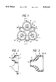
- FIG. 1 is a front elevation of a hermetic terminal cover according to a preferred embodiment of the present invention
- FIG. 2 is a sectional view of the hermetic terminal cover in FIG. 1, taken along a line A--A;
- FIG. 3 is an enlarged sectional view of one of terminal caps of the hermetic terminal cover in FIG. 1;
- FIG. 4 is a sectional view showing an assembled state, wherein the hermetic terminal cover of FIG. 1 is mounted onto a hermetic terminal;
- FIG. 5 is a sectional view of the hermetic terminal, wherein one of terminal pins of the hermetic terminal is inclined to another terminal pin, i.e. a degree of parallelization is poor between the shown terminal pins;
- FIG. 6 is a front elevation of the hermetic terminal cover of FIG. 1 for explaining its behavior when mounted to the hermetic terminal of FIG. 5;
- FIG. 7 is a front elevation of a hermetic terminal cover according to another preferred embodiment of the present invention.
- FIG. 8 is a sectional view showing an assembled state, wherein the hermetic terminal cover of FIG. 7 is mounted onto the hermetic terminal;
- FIG. 9 is a front elevation of a hermetic terminal cover according to still another preferred embodiment of the present invention.
- FIG. 10 is a front sectional view of a closed-type compressor according to a preferred embodiment of the present invention.
- FIG. 11 is an enlarged sectional view showing a relevant portion of the closed-type compressor of FIG. 10 around the hermetic terminal;
- FIG. 12 is a sectional view of the hermetic terminal
- FIG. 13 is a front elevation of a conventional hermetic terminal cover
- FIG. 14 is a sectional view showing an assembled state, wherein the conventional hermetic terminal cover of FIG. 13 is mounted onto the hermetic terminal.
- FIGS. 1 through 11 Since the hermetic terminal itself requires no modification from the foregoing conventional one, the same reference numerals as in FIGS. 12 to 14 are used in the following preferred embodiments of FIGS. 1 through 9 to designate or represent members or elements the same as or similar to those in FIGS. 12 to 14, so as to omit explanation thereof for avoiding redundant disclosure.
- FIG. 1 is a front elevation of a hermetic terminal cover according to a preferred embodiment of the present invention.
- FIG. 2 is a sectional view of the hermetic terminal cover in FIG. 1, taken along a line A--A.
- FIG. 3 is an enlarged sectional view of one of terminal caps of the hermetic terminal cover in FIG. 1.
- FIG. 4 is a sectional view showing an assembled state, wherein the hermetic terminal cover of FIG. 1 is mounted onto the hermetic terminal.
- FIG. 5 is a sectional view of the hermetic terminal, wherein one of terminal pins of the hermetic terminal is inclined to another terminal pin, i.e. a degree of parallelization is poor between the shown terminal pins.
- FIG. 6 is a front elevation of the hermetic terminal cover of FIG.
- FIG. 7 is a front elevation of a hermetic terminal cover according to another preferred embodiment of the present invention.
- FIG. 8 is a sectional view showing an assembled state, wherein the hermetic terminal cover of FIG. 7 is mounted onto the hermetic terminal.
- FIG. 9 is a front elevation of a hermetic terminal cover according to still another preferred embodiment of the present invention.
- a reference numeral 1 denotes the hermetic terminal cover of the preferred embodiment.
- the hermetic terminal cover 1 is made of polybutylene terephthalate by the injection molding, having a high oil resistance, a high refrigerant resistance, a high insulating characteristic and a high voltage resistance.
- the hermetic terminal cover 1 includes three terminal caps 2, 3 and 4 which are mutually coupled by respective ribs 6, 7 and 8.
- the terminal caps 2, 3 and 4 are mutually of the same shape similar to an upper portion of a bottle, as shown in FIG. 2.
- Each of the terminal caps 2, 3 and 4 covers the corresponding terminal strip 101 of the hermetic terminal 100, and includes a tubular seal section 10 of a relatively large diameter, a cover section 11 extending from the tubular seal section 10 and sharply tapering in a direction away from the tubular seal section 10, and a terminal pin receiving section 12 extending from the cover section 11 and moderately or loosely tapering in a direction away from the cover section 11.
- an inner diameter of the tubular seal section 10 is set equal to or slightly smaller than an outer diameter of the tubular section 105.
- the cover section 11 covers the exposed surface of the insulator 106 of the hermetic terminal 100 as shown in FIG. 4.
- the cover section 11 has an inner periphery whose section along a length of the corresponding terminal pin 107 forms a curved line of a circular arc and tapers toward the terminal pin receiving section 12.
- thicknesses of the cover section 11 are set larger than those of the remaining portions of the terminal cap 2 (3, 4), i.e. about between l mm and 3 mm.
- An inner periphery of the terminal pin receiving section 12 is of just a tapering shape toward its tip opening 13. An inner diameter of this tip opening 13 is set slightly smaller than a diameter of the terminal pin 107.
- each terminal cap has two of the ribs adjoined thereto.
- Each rib 6 (7, 8) extends from an outer periphery of the tubular seal section 10 such that the adjoining portions of the two ribs with the tubular seal section 10 are substantially in line with the tip opening 13 of the terminal pin receiving section 12 and located at symmetrical positions with respect to a line extending through the apex of the equilateral triangle 15 and the middle point on the corresponding base thereof, as shown in FIG. 1.
- each rib 6 (7, 8) has a shape of a circular arc with its radius being smaller than that of the terminal cap 2 (3, 4). Accordingly, each rib is laterally bulged with a sufficient margin of length.
- the three ribs 6, 7 and 8 have the same shape with each other so that a dashed line 16 connecting the middle points of the circular arc of the respective ribs 6, 7 and 8 also forms an equilateral triangle which is inverted by an angle of 180 degrees relative to the equilateral triangle drawn by the dashed line 15.
- a tangential line of each rib 6 (7, 8) is substantially in line with a normal line of the terminal cap 2 (3, 4) at the adjoining portion of the rib 6 (7, 8) with the corresponding tubular seal section 10 of the terminal cap, as shown in FIG. 1. This is effective for allowing the maximum freedom in the turning action of each terminal cap.
- the hermetic terminal cover 1 as structured above is mounted onto an inner side of the hermetic terminal 100, i.e. a side of the hermetic terminal 100 facing the interior of the closed-type compressor. Specifically, the hermetic terminal cover 1 is mounted onto the terminal strips 101 of the hermetic terminal 100 with its tubular seal sections 10 being tightly fitted around the corresponding metallic tubular sections 105, with its cover sections 11 being adjoining the exposed surfaces of the corresponding insulators 106, and with its terminal pin receiving sections 12 tightly receiving the corresponding terminal pins 107 therethrough.
- the terminal caps 2, 3 and 4 are respectively first brought into contact with the corresponding terminal pins 107 at their inner peripheries, and then slowly forced further toward the bottom of the metallic base 103 by operator's hands.
- a tip of each terminal pin 107 is first brought into contact with the inner periphery of the cover section 11.
- the tip of the terminal pin 107 is guided toward the terminal pin receiving section 12 along the tapered inner periphery of the cover section 11 as the hermetic terminal cover 1 slowly advances toward the bottom of the metallic base 103.
- the inner diameter of the tip opening 13 of the terminal pin receiving section 12 is set smaller than the diameter of the terminal pin 107, since the inner periphery of the terminal pin receiving section 12 is just tapered, the terminal pin receiving section 12 is forced enlarged as the terminal pin 107 slowly advances relative to the terminal pin receiving section 12. As a result, the tip of the terminal pin 107 passes through the tip opening 13 with its outer periphery being in tight contact with the inner periphery of the terminal pin receiving section 12.
- each terminal pin 107 After the tip of each terminal pin 107 passes through the tip opening 13, the three terminal caps 2, 3 and 4 are simultaneously and slowly forced further toward the bottom of the metallic base 103, keeping balance among the three terminal caps 2, 3 and 4. Subsequently, when the annular free end of each tubular seal section 10 remote from the tip opening 13 reaches the metallic tubular section 105 of the hermetic terminal 100, some more force is applied to each terminal cap so as to forcibly fit the tubular seal section 10 around the metallic tubular section 105 for firmly coupling them.
- the following operations may be performed for mounting the hermetic terminal cover 1 onto the hermetic terminal 100:
- the hermetic terminal cover 1 is forced onto the hermetic terminal 100 with the terminal cap 2 gradually returning to its normal posture from the posture shown in FIG. 6. Since a deviation of the non-parallel terminal pin 107 from the normal position is very small at a location where the non-parallel terminal pin 107 comes out from the insulator 106, the terminal cap 2 substantially returns to the normal position after the hermetic terminal cover 1 has been mounted onto the hermetic terminal 100, i.e. after the tubular seal section 10 of the terminal cap 2 has been firmly fitted around the tubular section 105 of the metallic base 103.
- the terminal cap 2 can be mounted onto the corresponding terminal strip 101 in a manner which ensures the tight connections between the tubular seal section 10 and the metallic tubular section 103 and between the terminal pin receiving section 12 and the terminal pin 107 as in the case of the terminal pin 107 being parallel with the other terminal pins 107. Further, since the ribs 6 and 8 have been deformed only temporally by the applied force, which does not cause permanent deformation thereof, these ribs return to their normal posture and no wrinkles remain after the hermetic terminal cover 1 has been mounted onto the hermetic terminal 100.
- each terminal cap 2 (3, 4) receives the corresponding two of the three ribs 6, 7 and 8 substantially on the diametrical line thereof, and each rib is of a shape of a circular arc having a radius of curvature smaller than that of the terminal cap.
- this structure of the ribs is preferable in view of allowing the large displacement of the terminal caps 2, 3 and 4.
- the structure of the ribs is not to be limited to the foregoing preferred embodiment.
- each rib may have a linear shape, a hook shape or others.
- FIG. 7 shows a modification of the hermetic terminal cover 1 as shown in FIG. 1.
- a hermetic terminal cover 30 of FIG. 7 only differs from the hermetic terminal cover 1 of FIG. 1 in a rib structure including a rib shape.
- a rib 31 of the hermetic terminal cover 30 forms a circumscribed circle of terminal caps 32, 33 and 34.
- the terminal caps 32, 33 and 34 are arranged at respective apexes of an equilateral triangle as in FIG. 1, and each rib component of the rib 31 is extended from radially outermost portions of the corresponding terminal caps with respect the center of the hermetic terminal cover 30.
- the rib components of the rib 31 have the same arc shape with each other, and an equilateral triangle which is angularly inverted by 180 degrees with respect to the equilateral triangle of the terminal caps is formed by apexes located at the middle points of the respective rib components. Accordingly, a radius of the annular rib 31 is equal to a radius of a circle which connects radially outermost points of the respective terminal caps 32, 33 and 34 with respect to the center of the hermetic terminal cover 30. Further, the radius of this circle, i.e. the circumscribed circle is substantially equal to a radius of the circular bottom of the metallic base 103.
- FIG. 9 shows a further modification of the hermetic terminal cover 1 as shown in FIG. 1.
- this modification is a combination of the foregoing preferred embodiments of FIGS. 1 and 7.
- the hermetic terminal cover of FIG. 9 includes ribs 35 which correspond to the ribs 6, 7 and 8 in FIG. 1 and a rib 36 which corresponds to the rib 31 in FIG. 7.
- the hermetic terminal cover is small in size and mass-produced. Accordingly, the injection molding is recommendable for producing the hermetic terminal cover.
- a special attention must be brought to a position or location where a weld line or mark is generated.
- the inner peripheries of the tubular seal section 10 and the terminal pin receiving section 12 must be formed smooth enough for ensuring the tight coupling with the metallic tubular section 105 and the terminal pin 107, respectively. Accordingly, when molding the hermetic terminal cover by the injection molding, the weld line should be prevented from generating at the tubular seal section 10 or the terminal pin receiving section 12 since the weld line deteriorates the smoothness of the inner peripheries thereof.
- molding material injection gates or mold gates are arranged at molding cavities which are for molding the respective terminal caps, and each mold gate is located equally distant from the corresponding ribs or the corresponding rib components.
- the mold gates are arranged at locations identified by arrows D, E and F, respectively.
- the mold gates are arranged at locations identified by arrows G, H and I in FIG. 7, and by arrows J, K and L in FIG. 9. It is desirable that each mold gate is located equally distant from a nozzle of the injection molding machine.
- thermoplastic resin injected through each mold gate first fills up the molding cavity for the terminal cap. After the molding cavity for the terminal cap is filled up, an excess portion of the thermoplastic resin flows into molding cavities for the ribs. Accordingly, the separately injected molding materials of the thermoplastic resin flow into the corresponding molding cavities for the ribs after completely filling up the cavities for the terminal caps. It is to be appreciated that, since the ribs and/or the rib components have the same shape with each other and the equilateral triangle is formed by the apexes located at the middle points of the respective ribs or the respective rib components and is angularly inverted by 180 degrees with respect to the equilateral triangle as identified by the dashed line 15 in FIG.
- the separately injected molding materials of the thermoplastic resin which flow into the molding cavities for the respective ribs and/or the respective rib components collide with each other at the middle points thereof to form the weld lines there.
- the terminal caps are uniformly molded with no weld line included.
- Material wells 37 or 38 in FIG. 7 or FIG. 9 may be provided at the molding cavities for the ribs or the rib components for ensuring formation of the weld lines at these material wells. The material wells further work to reinforce the ribs or the rib components at the weld lines which otherwise deteriorate the strength thereof.
- FIG. 10 is a front sectional view of the closed-type compressor according to a preferred embodiment of the present invention
- FIG. 11 is an enlarged sectional view showing a relevant portion of the closed-type compressor of FIG. 10 around the hermetic terminal.
- a reference numeral 40 denotes the closed-type compressor which is generally used in a refrigerator, a room air conditioner or the like.
- the closed-type compressor 40 includes a sealed case 41 in which an electric motor 42 and a compressor unit 43 are arranged in series as the conventional closed-type compressor.
- the electric motor 42 includes a rotor having a rotation shaft with a coil wound therearound, and stator coils provided around the rotor.
- the compressor unit 43 is operated by a rotational force or torque transmitted from the electric motor 42 for compressing the refrigerant. Since the electric motor 42 and the compressor unit 43 do not differ at all from the conventional ones, no further explanation thereof will be given hereinbelow.
- a hermetic terminal 44 is fixedly mounted to the sealed case 41 at a side remote from the compressor unit 43.
- the hermetic terminal 44 includes a dish-shaped metallic base 45, three glass insulators 46 and three terminal pins 47.
- the metallic base 45 is welded to the sealed case 41 and includes three holes 49 respectively defined by tubular sections 50 of the metallic base 45.
- Each terminal pin 47 is made of an alloy of iron, nickel and cobalt and passes through the center of the tubular section 50 with the glass insulator hermetically interposed between the terminal pin 47 and the tubular section 50. Accordingly, each terminal pin 47 is fixed in the tubular section 50 as being electrically insulated therefrom, and each hole 49 is hermetically closed by the insulator 46.
- the hermetic terminal cover 1 is mounted onto an inner side of the hermetic terminal 44, i.e. a side of the hermetic terminal facing the interior of the closed-type compressor 40.
- the hermetic terminal cover 1 employed herein is identical to that as shown in FIG. 1. Accordingly, the hermetic terminal cover 1 is mounted onto the hermetic terminal 44 with its tubular seal sections 10 and terminal pin receiving sections 12 being tightly fitted around the corresponding tubular sections 50 and the terminal pins 47 of the hermetic terminal 44.
- hermetic terminal cover 1 is mounted to the hermetic terminal 44 after the hermetic terminal 44 has been welded to the sealed case 41, since each of the terminal caps 2, 3 and 4 is allowed the large positional or displacement freedom as described before and is formed with the tapered inner peripheries as also described before, the mounting operation of the hermetic terminal cover 1 is facilitated.
- the terminal pins 47 respectively pass through between inside and outside of the sealed case 41 for feeding power to the internal electric motor 42. Specifically, the terminal pins 47 are connected to an external power source (not shown) outside the sealed case 41 and to a cluster 52 inside the sealed case 41. As shown in FIG. 11, an inward protruding portion 51 of each terminal pin 47 is received in an insertion hole 53 of the cluster 52.
- the cluster 52 includes electric wires 54 which are connected to the electric motor 42 for connecting the terminal pins 47 to the electric motor 42.
- the dimensional relationship is set such that a gap of about 0.1 mm to 1 mm is provided between an end surface 55 of the cluster 52 and an end surface 56 of the terminal pin receiving section 12 of each terminal cap 2 (3, 4) when the inward protruding portion 51 of each terminal pin 47 reaches a bottom of the insertion hole 53.
- the cluster 52 is fitted onto the terminal pins 47, the cluster 52 is prevented from abutting against the end surfaces 56 of the hermetic terminal cover 1 so as to ensure the reliable attachment of the cluster 52 to the terminal pins 47.
- the refrigerant is compressed in the compressor unit 43 driven by the electric motor 42.
- the oil 57 pooled in the sealed case 41 is agitated and compelled up to the hermetic terminal 44.
- the hermetic terminal 44 is exposed to and bathed with the oil 57 and the metallic powders included in the oil 57.
- the hermetic terminal 44 is protected by the hermetic terminal cover 1, i.e. each terminal strip is covered by the terminal cap 2 (3, 4) with the tubular seal section 10 tightly fitted around the metallic tubular section 50 and with the terminal pin receiving section 12 tightly fitted around the terminal pin 47, each terminal strip is protected from the metallic powders which otherwise directly hit each of the terminal strips.
- each terminal cap 2 (3, 4) is formed thicker than the remaining portions of the terminal cap, the metallic powders are prevented from approaching the surface of the insulator 46 closer than a distance defined by the thickness of the cover section 11. Accordingly, the metallic powders are largely spaced from the surface of the insulator 46 where the electric force lines are the largest in number.
- the hermetic terminal cover 1 not only prevents the metallic powders from adhering to the surfaces of the insulators 46, but also weakens the attraction force of the static electricity which is generated at the end portions of the metallic tubular sections 50 and exerted on the surface of the hermetic terminal cover 1.
- hermetic terminal cover 1 employed in FIG. 11 may be readily replaced by the foregoing hermetic terminal cover as shown in FIG. 7 or FIG. 9.
Landscapes
- Compressor (AREA)
Abstract
Description
Claims (12)
Applications Claiming Priority (2)
| Application Number | Priority Date | Filing Date | Title |
|---|---|---|---|
| JP4-061672 | 1992-03-18 | ||
| JP4061672A JP3020341B2 (en) | 1992-03-18 | 1992-03-18 | Airtight terminal protection cover |
Publications (1)
| Publication Number | Publication Date |
|---|---|
| US5391061A true US5391061A (en) | 1995-02-21 |
Family
ID=13177971
Family Applications (1)
| Application Number | Title | Priority Date | Filing Date |
|---|---|---|---|
| US08/030,978 Expired - Lifetime US5391061A (en) | 1992-03-18 | 1993-03-12 | Hermetic terminal cover and compressor incorporating same |
Country Status (2)
| Country | Link |
|---|---|
| US (1) | US5391061A (en) |
| JP (1) | JP3020341B2 (en) |
Cited By (21)
| Publication number | Priority date | Publication date | Assignee | Title |
|---|---|---|---|---|
| EP0685856A3 (en) * | 1994-05-31 | 1996-09-11 | Emerson Electric Co | Insulating arrangement for a fused hermetic terminal assembly. |
| US5769659A (en) * | 1995-12-13 | 1998-06-23 | Copeland Corporation | Plastic terminal box |
| US6150845A (en) * | 1999-06-01 | 2000-11-21 | Fairchild Semiconductor Corp. | Bus hold circuit with overvoltage tolerance |
| US6273754B1 (en) | 2000-04-13 | 2001-08-14 | Tecumseh Products Company | Protective covering for the terminal assembly of a hermetic compressor assembly |
| US6290528B1 (en) | 1998-07-14 | 2001-09-18 | Carrier Corporation | Electric power supply connector for sealed compressor |
| US6315528B1 (en) * | 1999-05-27 | 2001-11-13 | Scroll Technologies | Terminal connection in small area of scroll compressor and method for carrying out same |
| US6441311B2 (en) * | 1999-12-22 | 2002-08-27 | Matsushita Electric Industrial Co., Ltd. | Power supply terminal for use with a motor-driven compressor and method of insulating same |
| US20020155741A1 (en) * | 2001-05-04 | 2002-10-24 | Herrick Todd W. | Dielectric terminal design |
| US20030013343A1 (en) * | 2001-06-08 | 2003-01-16 | Matsushita Electric Industrial Co., Ltd. | Compressor with built-in motor and mobile structure using the same |
| US6556379B2 (en) * | 1999-11-22 | 2003-04-29 | Fuji Photo Film Co., Ltd. | Magnetic tape cassette, window member and resin molding product |
| US6776654B2 (en) | 2002-04-04 | 2004-08-17 | Scroll Technologies | Conduit retaining clip |
| US20100065305A1 (en) * | 2008-09-05 | 2010-03-18 | Schott Ag | Electrical lead-through for safety tanks |
| US20110103979A1 (en) * | 2008-06-23 | 2011-05-05 | Sanden Corporation | Electric compressor |
| US20120274163A1 (en) * | 2011-04-27 | 2012-11-01 | Toyota Jidosha Kabushiki Kaisha | Power unit |
| WO2013178687A1 (en) * | 2012-05-30 | 2013-12-05 | Tyco Electronics Amp Gmbh | Electrical connector element having a self-sealing contact receiving member and contact element therefor |
| FR2997797A1 (en) * | 2012-11-08 | 2014-05-09 | Valeo Japan Co Ltd | Assembly for electric compressor utilized for liquid refrigerant e.g. R134a circuit in electric car, has sealing unit insulating electric connection element of wall separating motor from control device on level of connection opening |
| US8794999B2 (en) * | 2012-08-10 | 2014-08-05 | Emerson Electric Co. | Hermetic terminal having pin-isolating feature |
| CN108349377A (en) * | 2015-11-16 | 2018-07-31 | 全耐塑料高级创新研究公司 | Tank including connector and method of connecting electrical equipment in tank |
| CN114207281A (en) * | 2019-10-08 | 2022-03-18 | 肖特日本株式会社 | Airtight terminal |
| CN114830443A (en) * | 2020-01-10 | 2022-07-29 | 川崎重工业株式会社 | Hermetic terminal and can valve device provided with hermetic terminal |
| EP4038699A4 (en) * | 2019-10-01 | 2023-11-01 | Hanon Systems | SEALING AND INSULATING ARRANGEMENT FOR A DEVICE FOR DRIVING A COMPRESSOR AND DEVICE FOR DRIVING A COMPRESSOR |
Families Citing this family (2)
| Publication number | Priority date | Publication date | Assignee | Title |
|---|---|---|---|---|
| JP5667314B1 (en) * | 2014-02-13 | 2015-02-12 | 株式会社フジクラ | connector |
| CN118575368A (en) * | 2022-01-28 | 2024-08-30 | 株式会社生方制作所 | Airtight terminal |
Citations (16)
| Publication number | Priority date | Publication date | Assignee | Title |
|---|---|---|---|---|
| US2458748A (en) * | 1945-05-01 | 1949-01-11 | Stupakoff Ceramic & Mfg Compan | Hermetic seal for electric terminals and the like |
| US3581191A (en) * | 1969-08-06 | 1971-05-25 | Varian Associates | Phase correlation for an rf spectrometer employing an rf carrier modulated by a pseudorandom sequence |
| US3605076A (en) * | 1969-08-21 | 1971-09-14 | Us Terminals Inc | Hermetically sealed terminal construction |
| US3721948A (en) * | 1972-03-02 | 1973-03-20 | Gen Electric | Terminal assembly |
| JPS5616777A (en) * | 1978-10-24 | 1981-02-18 | Saito Youichi | Tombstone housing shrine |
| US4252394A (en) * | 1979-05-16 | 1981-02-24 | Tecumseh Products Company | Hermetic compressor motor terminal |
| US4461925A (en) * | 1981-08-31 | 1984-07-24 | Emerson Electric Co. | Hermetic refrigeration terminal |
| US4480151A (en) * | 1982-07-19 | 1984-10-30 | Hilliard Dozier | Temperature stable hermetically sealed terminal |
| US4580003A (en) * | 1984-12-03 | 1986-04-01 | Emerson Electric Co. | Hermetic terminal assembly |
| US4584433A (en) * | 1984-12-03 | 1986-04-22 | Emerson Electric Co. | Hermetic terminal assembly |
| US4609774A (en) * | 1985-06-18 | 1986-09-02 | B & W Electronic Enclosures, Inc. | Electrical terminal construction with fusible section |
| US4700999A (en) * | 1983-07-07 | 1987-10-20 | Gmt Novotny Gmbh | Current leadthrough |
| JPS62271975A (en) * | 1986-05-20 | 1987-11-26 | Sanyo Electric Co Ltd | Air-tight terminal for enclosed-type compressor |
| US4786762A (en) * | 1988-03-03 | 1988-11-22 | Emerson Electric Co. | Sleeve arrangement for a hermetic terminal assembly |
| US4984973A (en) * | 1990-03-21 | 1991-01-15 | Tecumseh Products Company | Hermetic motor compressor unit having a hermetic terminal with electrically insulating anti-tracking cap |
| US5017740A (en) * | 1990-04-02 | 1991-05-21 | Emerson Electric Co. | Fused hermetic terminal assembly including a pin guard and lead wire end connection securing device associated therewith |
Family Cites Families (1)
| Publication number | Priority date | Publication date | Assignee | Title |
|---|---|---|---|---|
| JP3114582U (en) | 2005-07-08 | 2005-10-27 | 日本工機株式会社 | Hanger type telescopic gate |
-
1992
- 1992-03-18 JP JP4061672A patent/JP3020341B2/en not_active Expired - Lifetime
-
1993
- 1993-03-12 US US08/030,978 patent/US5391061A/en not_active Expired - Lifetime
Patent Citations (16)
| Publication number | Priority date | Publication date | Assignee | Title |
|---|---|---|---|---|
| US2458748A (en) * | 1945-05-01 | 1949-01-11 | Stupakoff Ceramic & Mfg Compan | Hermetic seal for electric terminals and the like |
| US3581191A (en) * | 1969-08-06 | 1971-05-25 | Varian Associates | Phase correlation for an rf spectrometer employing an rf carrier modulated by a pseudorandom sequence |
| US3605076A (en) * | 1969-08-21 | 1971-09-14 | Us Terminals Inc | Hermetically sealed terminal construction |
| US3721948A (en) * | 1972-03-02 | 1973-03-20 | Gen Electric | Terminal assembly |
| JPS5616777A (en) * | 1978-10-24 | 1981-02-18 | Saito Youichi | Tombstone housing shrine |
| US4252394A (en) * | 1979-05-16 | 1981-02-24 | Tecumseh Products Company | Hermetic compressor motor terminal |
| US4461925A (en) * | 1981-08-31 | 1984-07-24 | Emerson Electric Co. | Hermetic refrigeration terminal |
| US4480151A (en) * | 1982-07-19 | 1984-10-30 | Hilliard Dozier | Temperature stable hermetically sealed terminal |
| US4700999A (en) * | 1983-07-07 | 1987-10-20 | Gmt Novotny Gmbh | Current leadthrough |
| US4580003A (en) * | 1984-12-03 | 1986-04-01 | Emerson Electric Co. | Hermetic terminal assembly |
| US4584433A (en) * | 1984-12-03 | 1986-04-22 | Emerson Electric Co. | Hermetic terminal assembly |
| US4609774A (en) * | 1985-06-18 | 1986-09-02 | B & W Electronic Enclosures, Inc. | Electrical terminal construction with fusible section |
| JPS62271975A (en) * | 1986-05-20 | 1987-11-26 | Sanyo Electric Co Ltd | Air-tight terminal for enclosed-type compressor |
| US4786762A (en) * | 1988-03-03 | 1988-11-22 | Emerson Electric Co. | Sleeve arrangement for a hermetic terminal assembly |
| US4984973A (en) * | 1990-03-21 | 1991-01-15 | Tecumseh Products Company | Hermetic motor compressor unit having a hermetic terminal with electrically insulating anti-tracking cap |
| US5017740A (en) * | 1990-04-02 | 1991-05-21 | Emerson Electric Co. | Fused hermetic terminal assembly including a pin guard and lead wire end connection securing device associated therewith |
Cited By (31)
| Publication number | Priority date | Publication date | Assignee | Title |
|---|---|---|---|---|
| EP0685856A3 (en) * | 1994-05-31 | 1996-09-11 | Emerson Electric Co | Insulating arrangement for a fused hermetic terminal assembly. |
| US5769659A (en) * | 1995-12-13 | 1998-06-23 | Copeland Corporation | Plastic terminal box |
| US20030151861A1 (en) * | 1998-07-14 | 2003-08-14 | Moore Billy W. | Electric power supply connector for sealed compressor |
| US6290528B1 (en) | 1998-07-14 | 2001-09-18 | Carrier Corporation | Electric power supply connector for sealed compressor |
| US6916210B2 (en) | 1998-07-14 | 2005-07-12 | Carrier Corporation | Electric power supply connector for sealed compressor |
| US6315528B1 (en) * | 1999-05-27 | 2001-11-13 | Scroll Technologies | Terminal connection in small area of scroll compressor and method for carrying out same |
| US6150845A (en) * | 1999-06-01 | 2000-11-21 | Fairchild Semiconductor Corp. | Bus hold circuit with overvoltage tolerance |
| US6556379B2 (en) * | 1999-11-22 | 2003-04-29 | Fuji Photo Film Co., Ltd. | Magnetic tape cassette, window member and resin molding product |
| US6441311B2 (en) * | 1999-12-22 | 2002-08-27 | Matsushita Electric Industrial Co., Ltd. | Power supply terminal for use with a motor-driven compressor and method of insulating same |
| US6273754B1 (en) | 2000-04-13 | 2001-08-14 | Tecumseh Products Company | Protective covering for the terminal assembly of a hermetic compressor assembly |
| US6910904B2 (en) * | 2001-05-04 | 2005-06-28 | Tecumseh Products Company | Compressor with terminal assembly having dielectric material |
| US20050124203A1 (en) * | 2001-05-04 | 2005-06-09 | Herrick Todd W. | Compressor with terminal assembly having dielectric material |
| US20020155741A1 (en) * | 2001-05-04 | 2002-10-24 | Herrick Todd W. | Dielectric terminal design |
| US7025614B2 (en) | 2001-05-04 | 2006-04-11 | Tecumseh Products Company | Compressor with terminal assembly having dielectric material |
| US6866487B2 (en) * | 2001-06-08 | 2005-03-15 | Matsushita Electric Industrial Co., Ltd. | Compressor with built-in motor and mobile structure using the same |
| US20030013343A1 (en) * | 2001-06-08 | 2003-01-16 | Matsushita Electric Industrial Co., Ltd. | Compressor with built-in motor and mobile structure using the same |
| US6776654B2 (en) | 2002-04-04 | 2004-08-17 | Scroll Technologies | Conduit retaining clip |
| US20110103979A1 (en) * | 2008-06-23 | 2011-05-05 | Sanden Corporation | Electric compressor |
| US20100065305A1 (en) * | 2008-09-05 | 2010-03-18 | Schott Ag | Electrical lead-through for safety tanks |
| US8461456B2 (en) * | 2008-09-05 | 2013-06-11 | Schott Ag | Electrical lead-through for safety tanks |
| US20120274163A1 (en) * | 2011-04-27 | 2012-11-01 | Toyota Jidosha Kabushiki Kaisha | Power unit |
| WO2013178687A1 (en) * | 2012-05-30 | 2013-12-05 | Tyco Electronics Amp Gmbh | Electrical connector element having a self-sealing contact receiving member and contact element therefor |
| US8794999B2 (en) * | 2012-08-10 | 2014-08-05 | Emerson Electric Co. | Hermetic terminal having pin-isolating feature |
| FR2997797A1 (en) * | 2012-11-08 | 2014-05-09 | Valeo Japan Co Ltd | Assembly for electric compressor utilized for liquid refrigerant e.g. R134a circuit in electric car, has sealing unit insulating electric connection element of wall separating motor from control device on level of connection opening |
| CN108349377A (en) * | 2015-11-16 | 2018-07-31 | 全耐塑料高级创新研究公司 | Tank including connector and method of connecting electrical equipment in tank |
| EP4038699A4 (en) * | 2019-10-01 | 2023-11-01 | Hanon Systems | SEALING AND INSULATING ARRANGEMENT FOR A DEVICE FOR DRIVING A COMPRESSOR AND DEVICE FOR DRIVING A COMPRESSOR |
| US12027796B2 (en) | 2019-10-01 | 2024-07-02 | Hanon Systems | Sealing and insulating arrangement for a device used for driving a compressor and device for driving a compressor |
| CN114207281A (en) * | 2019-10-08 | 2022-03-18 | 肖特日本株式会社 | Airtight terminal |
| CN114207281B (en) * | 2019-10-08 | 2024-06-25 | 肖特股份有限公司 | Airtight terminal |
| US12035498B2 (en) | 2019-10-08 | 2024-07-09 | Schott Ag | Airtight terminal |
| CN114830443A (en) * | 2020-01-10 | 2022-07-29 | 川崎重工业株式会社 | Hermetic terminal and can valve device provided with hermetic terminal |
Also Published As
| Publication number | Publication date |
|---|---|
| JP3020341B2 (en) | 2000-03-15 |
| JPH05263762A (en) | 1993-10-12 |
Similar Documents
| Publication | Publication Date | Title |
|---|---|---|
| US5391061A (en) | Hermetic terminal cover and compressor incorporating same | |
| US4840547A (en) | Compressor including protective cap for hermetic terminal | |
| US6404086B1 (en) | Anisotropic magnet brushless motor having a rotor with elastic insulating support structure | |
| JP5683536B2 (en) | Electric compressor | |
| EP1902496B1 (en) | Electric power terminal feed-through | |
| US5731646A (en) | Heat-protected motor housing with metal casing and plastic plate | |
| US9831747B2 (en) | Motor-driven compressor | |
| US20050124203A1 (en) | Compressor with terminal assembly having dielectric material | |
| EP1890360B1 (en) | Electronic connector and method of attachment | |
| EP2131473A2 (en) | Sealed rolled pole housing for an electric motor | |
| CN113969821A (en) | Electronic water pumps and vehicles | |
| CN207117348U (en) | Plastic packaging motor with anti-electrocorrosion structure | |
| JP5897417B2 (en) | Cover member for igniter | |
| JP3056356B2 (en) | Automotive sensors | |
| US20020033269A1 (en) | Electrical tubing assembly with hermetically sealed ends | |
| CA1221752A (en) | Current leadthrough | |
| JP4431234B2 (en) | Lead wire sealing mechanism from cavity | |
| US20200203940A1 (en) | Opening closure device for case | |
| CN100499324C (en) | Stepping motor and method of manufacturing the same | |
| KR102267161B1 (en) | Flexible Insulating Cap for Terminal | |
| US6737947B1 (en) | Assembly for sealing electrical leads to internal electrical device | |
| US10895314B2 (en) | Gear box, reduction gear equipped with gear box, motor unit, mold for manufacturing gear box, and manufacturing method of gear box | |
| JP5442591B2 (en) | Manufacturing method of gasket | |
| JP2582151Y2 (en) | light bulb | |
| JPH0694736A (en) | Electromagnetic induction type rotation detector and manufacturing method |
Legal Events
| Date | Code | Title | Description |
|---|---|---|---|
| STPP | Information on status: patent application and granting procedure in general |
Free format text: APPLICATION UNDERGOING PREEXAM PROCESSING |
|
| AS | Assignment |
Owner name: MATSUSHITA REFRIGERATION COMPANY, JAPAN Free format text: ASSIGNMENT OF ASSIGNORS INTEREST.;ASSIGNORS:IIZUKA, TATSUYUKI;SUZUKI, ETSURO;REEL/FRAME:006495/0530 Effective date: 19930309 |
|
| FEPP | Fee payment procedure |
Free format text: PAYOR NUMBER ASSIGNED (ORIGINAL EVENT CODE: ASPN); ENTITY STATUS OF PATENT OWNER: LARGE ENTITY |
|
| FPAY | Fee payment |
Year of fee payment: 4 |
|
| FPAY | Fee payment |
Year of fee payment: 8 |
|
| FPAY | Fee payment |
Year of fee payment: 12 |
|
| AS | Assignment |
Owner name: MATSUSHITA ELECTRIC INDUSTRIAL CO., LTD., JAPAN Free format text: MERGER;ASSIGNOR:MATSUSHITA REFRIGERATION COMPANY;REEL/FRAME:021996/0193 Effective date: 20080401 Owner name: PANASONIC CORPORATION, JAPAN Free format text: CHANGE OF NAME;ASSIGNOR:MATSUSHITA ELECTRIC INDUSTRIAL CO., LTD.;REEL/FRAME:021996/0204 Effective date: 20081001 |