US5376020A - Canopy for an exit light - Google Patents
Canopy for an exit light Download PDFInfo
- Publication number
- US5376020A US5376020A US08/022,066 US2206693A US5376020A US 5376020 A US5376020 A US 5376020A US 2206693 A US2206693 A US 2206693A US 5376020 A US5376020 A US 5376020A
- Authority
- US
- United States
- Prior art keywords
- box portion
- lower box
- opposing walls
- pair
- upper box
- Prior art date
- Legal status (The legal status is an assumption and is not a legal conclusion. Google has not performed a legal analysis and makes no representation as to the accuracy of the status listed.)
- Expired - Fee Related
Links
- 238000010079 rubber tapping Methods 0.000 claims description 3
- 230000000295 complement effect Effects 0.000 claims 1
- 238000000034 method Methods 0.000 abstract description 8
- 238000009434 installation Methods 0.000 description 5
- 238000004519 manufacturing process Methods 0.000 description 5
- 238000012423 maintenance Methods 0.000 description 3
- 239000004677 Nylon Substances 0.000 description 1
- 208000027418 Wounds and injury Diseases 0.000 description 1
- 229910045601 alloy Inorganic materials 0.000 description 1
- 239000000956 alloy Substances 0.000 description 1
- 238000010276 construction Methods 0.000 description 1
- 230000006378 damage Effects 0.000 description 1
- 238000009429 electrical wiring Methods 0.000 description 1
- 208000014674 injury Diseases 0.000 description 1
- 239000003562 lightweight material Substances 0.000 description 1
- 239000000463 material Substances 0.000 description 1
- 230000013011 mating Effects 0.000 description 1
- QSHDDOUJBYECFT-UHFFFAOYSA-N mercury Chemical compound [Hg] QSHDDOUJBYECFT-UHFFFAOYSA-N 0.000 description 1
- 229910052751 metal Inorganic materials 0.000 description 1
- 239000002184 metal Substances 0.000 description 1
- 150000002739 metals Chemical class 0.000 description 1
- 229920001778 nylon Polymers 0.000 description 1
- 239000004033 plastic Substances 0.000 description 1
- 238000001228 spectrum Methods 0.000 description 1
Images

Classifications
-
- H—ELECTRICITY
- H02—GENERATION; CONVERSION OR DISTRIBUTION OF ELECTRIC POWER
- H02G—INSTALLATION OF ELECTRIC CABLES OR LINES, OR OF COMBINED OPTICAL AND ELECTRIC CABLES OR LINES
- H02G3/00—Installations of electric cables or lines or protective tubing therefor in or on buildings, equivalent structures or vehicles
- H02G3/02—Details
- H02G3/08—Distribution boxes; Connection or junction boxes
- H02G3/18—Distribution boxes; Connection or junction boxes providing line outlets
- H02G3/20—Ceiling roses or other lighting sets
-
- F—MECHANICAL ENGINEERING; LIGHTING; HEATING; WEAPONS; BLASTING
- F21—LIGHTING
- F21V—FUNCTIONAL FEATURES OR DETAILS OF LIGHTING DEVICES OR SYSTEMS THEREOF; STRUCTURAL COMBINATIONS OF LIGHTING DEVICES WITH OTHER ARTICLES, NOT OTHERWISE PROVIDED FOR
- F21V21/00—Supporting, suspending, or attaching arrangements for lighting devices; Hand grips
- F21V21/02—Wall, ceiling, or floor bases; Fixing pendants or arms to the bases
- F21V21/03—Ceiling bases, e.g. ceiling roses
-
- Y—GENERAL TAGGING OF NEW TECHNOLOGICAL DEVELOPMENTS; GENERAL TAGGING OF CROSS-SECTIONAL TECHNOLOGIES SPANNING OVER SEVERAL SECTIONS OF THE IPC; TECHNICAL SUBJECTS COVERED BY FORMER USPC CROSS-REFERENCE ART COLLECTIONS [XRACs] AND DIGESTS
- Y10—TECHNICAL SUBJECTS COVERED BY FORMER USPC
- Y10S—TECHNICAL SUBJECTS COVERED BY FORMER USPC CROSS-REFERENCE ART COLLECTIONS [XRACs] AND DIGESTS
- Y10S362/00—Illumination
- Y10S362/812—Signs
-
- Y—GENERAL TAGGING OF NEW TECHNOLOGICAL DEVELOPMENTS; GENERAL TAGGING OF CROSS-SECTIONAL TECHNOLOGIES SPANNING OVER SEVERAL SECTIONS OF THE IPC; TECHNICAL SUBJECTS COVERED BY FORMER USPC CROSS-REFERENCE ART COLLECTIONS [XRACs] AND DIGESTS
- Y10—TECHNICAL SUBJECTS COVERED BY FORMER USPC
- Y10S—TECHNICAL SUBJECTS COVERED BY FORMER USPC CROSS-REFERENCE ART COLLECTIONS [XRACs] AND DIGESTS
- Y10S439/00—Electrical connectors
- Y10S439/911—Safety, e.g. electrical disconnection required before opening housing
Definitions
- the present invention relates to an apparatus and method for mounting a fixture to an electric box in a ceiling. More particularly, the present invention relates to a detachable two-piece canopy, for mounting an exit sign to the ceiling, which is usable so that one piece of the canopy is mounted to the ceiling while the second piece of the canopy is mounted to the exit sign with provisions to separately depend from the ceiling mounted piece while the electrical connections are made.
- exit signs in these environments are installed with great difficulty in that the installer must stand on a ladder and with one arm elevate an exit sign with a single piece canopy attached thereto and then with the remaining free hand attempt to attach the electrical wiring prior to securely mounting the sign to a standard ceiling fixture plate mounted in the ceiling.
- Exit signs are relatively heavy because they have a battery back-up which can continue to light the exit sign after the power to the exit sign is cut off. Since the exit sign is so heavy and because a one-piece canopy is used, one person must connect the exit sign to the ceiling at great risk of injury, i.e., falling from the ladder or accidentally dropping the fixture in an effort to maintain balance on the ladder.
- the exit sign may be set on a convenient surface, i.e., the top of the ladder, providing the ceiling wires and/or exit fixture wires are sufficiently long to permit this procedure. Once the wires are connected, they are folded and set inside of the canopy and the canopy is then connected to the ceiling fixture plate in the ceiling from which the exit sign will suspend.
- the above-mentioned prior art canopy for exit signs requires either a balancing act by the installer, an extra person to hold the exit sign, or a surface near the ceiling on which to set the exit sign while the wires of the exit sign and the ceiling wires are being spliced together.
- the prior art canopy used on exit signs is not cost effective to install because the installation is not safety conscious and it is time consuming and burdensome. Further, the same disadvantages are experienced each time any maintenance is performed on an exit sign using the prior art canopy.
- U.S. Pat. No. 4,199,803 to Hunt is an example of an assembly and method for mounting a mercury vapor floodlight fixture to a bracket in the ceiling.
- Hunt discloses a double-ended hook member that has one end connected to a hole in a bracket connected to the ceiling, and the other end of the hook connected to a hole in the side of the flood light fixture housing so that the housing may be suspended from the bracket member while the electrical connections are made.
- the hook must be removed before the fixture can be guided onto the ceiling bracket and attached thereto.
- this solution cannot be used.
- U.S. Pat. Nos. 4,368,506, to Rapp; 4,300,190, to Mershon; and 4,222,093, to Garcia, et al teach devices that can be used to mount a lighting fixture to a ceiling or wall and will provide a means for suspending the lighting fixture in an open position while the wires are being connected.
- special ceiling brackets must be used to accommodate the features of the invention and such brackets are expensive.
- U.S. Pat. No. 4,368,506 to Rapp teaches the use of a base connected to the ceiling and a bracket mounted to a luminaire.
- the bracket has a pair of upwardly extending members which are adapted to mount to side portions which are connected to the base.
- the upwardly extending members have a complex arrangement of slots which are adapted to receive posts which are connected to the base.
- the slots are aligned in a novel arrangement to provide a means for hanging the luminaire while the electrical connections are being made, and to then provide a means for supporting the luminaire while in a closed position.
- Rapp teaches a novel arrangement of slots and associated posts in order to achieve its primary object of hanging a luminaire from a bracket while the electrical connections are being made.
- Rapp's solution is very expensive to manufacture and is unsightly.
- U.S. Pat. No. 4,222,093, to Garcia et al. teaches a quick connect and detach light fixture which includes a back plate adapted to be secured to a wall and a fixture supporting plate, preferably by means of an opening associated with the back plate and a corresponding complemental pivot pin secured to the fixture supporting plate. This combination is expensive to manufacture and could result in the fixture accidentally unhooking from the back plate while the wires are electrically connected.
- U.S. Pat. No. 4,300,190, to Mershon teaches a special purpose T-shaped bracket which is attached to the intended mounting surface.
- a mating plate designed to engage the T-shaped bracket attaches to the lighting fixture.
- the T-shaped bracket permits the fixture to hang therefrom while the electrical connections are being made. Note, however, that the need for a special T-shaped bracket and associated plate makes this solution expensive and impossible to adapt to the current standard ceiling fixture plates that are used in industry today.
- a canopy which is adapted to be mounted to the present ceiling plate, is inexpensive to manufacture, and provides for safe installation of an exit sign to a ceiling plate.
- the present invention relates to an improved apparatus and method for mounting an exit sign to a standard electric box mounted in a ceiling or wall.
- the apparatus is a canopy made up of two pieces--an upper portion which connects to the electric box in the ceiling, and a lower portion detachable from the upper portion which connects to the exit sign. Both portions are snapped together and are adapted to pivot with respect to each other so that the electrical connections can be safely made.
- the upper portion and the lower portion of the two-piece canopy are similar in size and shape. Both are five sided boxes having a base portion and four walls.
- the base of each portion may be of any shape but is typically rectangular.
- the base of one portion is slightly smaller than the base of the other portion so that the smaller portion may fit within the larger portion in order to provide a completely closed box in which to contain the electrical connections between the wires in the ceiling and the wires of the exit sign.
- the upper portion of the canopy is attached to a standard electric box in the ceiling and the electric wires coming from the electric box are pulled through an aperture in the upper portion of the canopy.
- the lower portion of the canopy is attached to the exit sign and the wires of the exit sign are pulled through an aperture in the lower portion of the canopy.
- the upper and lower portions of the canopy are adapted to be connected together by the use of a dimple and dimple-socket arrangement or a post and post-hole arrangement with an established, preselected bias condition between the walls of the lower and upper portions of the canopy.
- the lower portion of the canopy is then connected to the upper portion of the canopy by snapping the two together so that the lower canopy portion and the exit sign connected thereto are hinged about the dimple socket or post and post hole arrangement from the upper canopy portion in an open position exposing the wires to be connected.
- the ceiling wires are spliced to the exit sign wires, and wire connectors are then connected to the spliced wires to cover the connection.
- the wires and the wire connectors are then folded to fit within the canopy and the canopy is pivoted about the hinged point into the closed position and can then be locked closed by any appropriate means.
- a primary object of the present invention is to provide a method and cost effective apparatus that will enable one person, without assistance, to install an exit sign to an electric box in a ceiling. Additionally, an object of the present invention is to provide a method and apparatus that will accomplish the primary objective of the present invention in a highly cost-effective manner.
- Another object of the present invention is provide a method and apparatus that will be safe to install and will be safe to use in a wide spectrum of operating conditions.
- a further object of the present invention is to provide a canopy for mounting an exit sign to the ceiling that will completely enclose the electrical connections between the ceiling wires and the wires of the exit sign but is yet easy to install and inexpensive to manufacture.
- the invention includes a two-piece canopy to facilitate the mounting of the exit sign to the electric box in a manner which allows the installer to connect the wires while the exit sign depends from the electric box via the two-piece canopy, and to then close the canopy so that the electrical wires are contained within the closed canopy and the exit sign is secured to the ceiling.
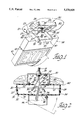
- FIG. 1 is a perspective view of one embodiment of the invention, illustrating the two-piece canopy in the open position with the wires not shown to clearly illustrate the exit sign attached to the lower portion of the canopy;
- FIG. 2 is a side view of the two-piece canopy in the closed position, illustrating the attachment of the exit sign to the lower portion of the canopy and the attachment of the upper portion of the canopy to the electric box as well as the electrical wire connections;
- FIG. 3 is a perspective side view of an alternate two-piece canopy and exit sign mounted to a ceiling and showing the two-piece canopy in a partially open position, illustrating the use of a pre-attached electrical plug-in connector, made up of a male connector mounted in the lower box portion and a female connector mounted in the upper box portion, which is used to establish and break the electrical connection concurrently with the opening and closing of the two-piece canopy.
- a pre-attached electrical plug-in connector made up of a male connector mounted in the lower box portion and a female connector mounted in the upper box portion, which is used to establish and break the electrical connection concurrently with the opening and closing of the two-piece canopy.
- FIG. 1 shows the two-piece canopy 10 in the open hinged position.
- the two-piece canopy 10 embodies an upper box portion 20 and a lower box portion 30.
- the two-piece canopy 10 is preferably made out of a strong lightweight material such as plastic or nylon in order to reduce weight and cost.
- the two-piece canopy 10 can also be made using metals, alloys, or other materials.
- FIGS. 1 and 2 show the upper box portion 20 mounted to the standard ceiling electrical box 70 by screws 39.
- the upper box portion 20 has a base portion 21 which is shown as being square in shape, but may be rectangular or another shape.
- the base portion 21 of the upper box portion 20 has a relatively large aperture 26 through which the leads of a ceiling wire 91 are passed.
- the base portion 21 also has slots 52 on each side of the aperture 26. The slots 52 are positioned to match up with standard threaded holes 73 of the standard ceiling mounted electrical box 70.
- the upper box portion 20 also has wall portions 22, 23, 24, and 25. Each wall portion is attached at an edge of the base portion 21. Thus, the base portion 21 and the wall portions 22, 23, 24, and 25 form a five-sided box.
- the wall portions 22 and 24 constitute a first pair of opposing walls of the upper box portion 20, and the wall portions 23 and 25 constitute a second pair of opposing walls of the upper box portion 20.
- the wall portions 22 and 24 each have holes 27 and holes 28 or similar type orifice or slot located therein, with the hole 28 of the respective wall portions 22 and 24 being located at the end near the wall portion 25 and the hole 27 being located near the wall portion 23. The purpose of the holes 27 and 28 will be described hereinafter.
- the lower box portion 30, shown in FIG. 1, is very similar to the upper box portion 20.
- the lower box portion 30 has a bottom 31 and four wall portions 32, 33, 34, and 35, each attached at an edge of the bottom 31, thereby forming a five-sided box.
- Each of these wall portions corresponds to the wall portions 22, 23, 24, and 25 of the upper box portion 20 but are smaller in overall size so that the lower box portion may be contained within the upper box portion.
- the walls portions 32 and 34 constitute a first pair of opposing walls of the lower box portion 30, and the wall portions 33 and 35 constitute a second pair of opposing walls of the lower box portion 30.
- the wall portions 32 and 34 each have holes 38 located in an end near the wall portion 35.
- the holes 38 are located on the wall portions 32 and 34 so that they will align with the holes 28 of the wall portions 22 and 24 of the upper box portion 20 when the lower box portion 30 is closed into the upper box portion 20.
- the wall portions 32 and 34 of the lower box portion 30 each have a post member 37 which is essentially an outwardly extending peg or peg portion or dimple extension located near the wall portion 33.
- the post members or dimple extensions 37 are located on the wall portions 32 and 34 so that they will align with the holes 27 of the wall portions 22 and 24 when the lower box portion 30 is inserted in the upper box portion 20.
- the holes or orifices 27 are provided for receiving the outwardly extending ember 37.
- the post members 37 are located on the wall portions 32 and 34 of the lower box portion 30 in such a manner so that when the lower box portion 30 is attached to the upper box portion 20 the lower box portion 30 will pivot with respect to the upper box portion 20 and the wall portion 33 of the lower box portion 30 will clear the wall portion 23 of the upper box portion 20.
- the overall depth of the lower box portion 30 is relatively smaller in size in the front to back direction (opposing walls 33 and 35) than the base portion 21 of the upper box portion 20 so that the wall portions 33 and 35 of the lower box portion 30 will fit within the wall portions 23 and 25 of the upper box portion 20 and permit pivoting of the lower box portion with respect to the upper box portion.
- the opposing wall portions 33 and 35 are actually somewhat larger in distance apart than the opposing wall portions 23 and 25 of the upper box portion 20. This is necessary to establish a pre-bias condition between the upper and lower box portions so that when the two portions are assembled together a bias exists between these wall portions which provides for a force to maintain the hinging relationship described below.
- the upper box portion 20 is shown mounted adjacent to the ceiling 60 through the use of the standard ceiling mounted electrical box 70 which has been installed in the ceiling 60.
- the ceiling wire 91 is generally brought into the electrical box 70 through a relatively large aperture 78 in the top of the electrical box.
- the ceiling wire 91 is made up of a ground wire 95, a first lead 96, and a second lead 97.
- the ceiling wire 91 is shown as a standard 110 volt wire.
- the ground wire 95 of the ceiling wire 91 is connected to a ground screw 72 of the electrical box 70 in order to ground the electrical box 70 and ultimately to ground the exit sign.
- the upper box portion 20 is connected to the electrical box 70 through the use of the screws 39 inserted through the slots 52 in the upper box portion 20 and into the threaded holes 73 of the electrical box 70.
- the upper box portion 20 is mounted to the ceiling while the lower box portion 30 is connected to the exit sign 40.
- the bottom 31 of the lower box portion 30 has an aperture 36 located so that it will align with an aperture 46 in the top 45 of the power pack 44 or with a similar aperture located in the top 42 of the exit sign 40. Leads 66 and 67 and a ground wire 65 of the exit sign 40 are pulled through the aperture 46 in the top of the power pack 44 and the aperture 36 in the lower box portion 30.
- the bottom 31 has slots 53 which are positioned to line-up with holes in the top 45 of the power pack 44.
- the bottom 31 is connected to the top 45 through the use of screws 29 inserted through the slots 53 and the holes in the top 42 of the power pack 44.
- the lower box portion 30 may be connected to the upper box portion through the use of a snap together arrangement as shown in FIGS. 1 and 2 or by the use of post members mounted to the opposing walls 32 and 34 of the lower box portion 30 combined with the slots formed in the opposing wall portions 22 and 24 of the upper box portion 20 as shown in the embodiment of FIG. 3.
- the lower box portion 30 is connected to the upper box portion 20 by inserting the outwardly protruding poet member or dimple extension 37 of the wall portions 32 and 34 in the holes 27 of the wall portions 22 and 24.
- the walls are gently squeezed together to fit the opposing walls 32 and 34 of the lower box portion 30 between the opposing walls 22 and 24 of the upper box portion 20.
- the lower box portion 30 is then further inserted into the upper box portion 20 until the outwardly protruding dimples snap into the holes 27 in the upper box portion 20 to establish a pivot about which the lower box portion and associated sign attached thereto can be suspended.
- the lower box portion 30 depends from the upper box portion 20 in an open manner, and the ceiling wires and the exit sign wires are easily accessed to finalize the installation.
- the leads 96 and 97 and the ground wire 95 of the ceiling wire 91 can easily be spliced together with the corresponding leads 66 and 67 and the ground wire 65 of the exit sign 40.
- Standard wire connectors 90 are then used to cover the spliced wires.
- the lower box portion 30 may be pivoted to close with the upper box portion 20 and then secured in place in any convenient manner such as with a self-tapping screw inserted in the hole 28 of the upper box portion and the hole 38 in the lower box portion which is in line with the hole 28 when the lower box portion is pivoted into the upper box portion.
- the lower box portion 30 may be secured closed through the use of the step and ratchet arrangement illustrated on the wall portions 25 and 35 of the alternate embodiment shown in FIG. 3.
- FIG. 3 shows an alternative embodiment of the invention in which an electrical connector made up of a female member 100 and a male member 102 is used in conjunction with the two-piece canopy 10.
- the female member 100 of the electrical connector is attached to the base portion 21 of the upper box portion 20 and has receptacles 103 located therein.
- the male member 102 is attached to the bottom portion 31 of the lower box portion 30 and has prongs 104.
- the leads 96 and 97 and the ground wire 95 of the ceiling wire 91 are connected to the female member 100 in any convenient manner, and the leads 66 and 67 and the ground wire 65 of the exit sign 40 are connected to the male member 102 in any convenient manner.
- the ground wire 95 is also connected to the ground screw 72 of the upper box portion 20.
- the female member 100 and the male member 102 are located within their respective box portions such that when the lower box portion 30 is closed with the upper box portion 20 the prongs 104 of the male member 102 are inserted into the receptacles 103 of the female member 100 thereby completing a circuit between the ceiling wire 91 and the exit sign 40.
- the circuit is broken and power to the exit sign will be cut off automatically so that it may be safely serviced.
- FIG. 3 also illustrates an alternative to the dimple and socket arrangement shown in FIGS. 1 and 2 to establish a pivot about which the lower box portion can rotate with respect to the upper box portion.
- the upper box portion has slots or grooves in the opposing walls 22 and 24 while each of the opposing walls 32 and 34 of the lower box portion 30 has a post member protruding therefrom.
- the distance between the post members and the opposing walls 32 and 34 of the lower box portion is greater than the distance between the opposing walls 22 and 24 of the upper box portion 20 to establish a pre-bias between the upper and lower box portions.
- one of the post members in the lower box portion is positioned in the slot and the lower box portion is squeezed together until the other post member is moved between the opposing walls 22 and 24 of the upper box portion.
- the lower box portion is then moved into the upper box portion until the other post member snaps into the other slot or groove 55 of the opposing walls 22 and 24.
- the lower box portion depends from the upper box portion and may pivot with respect thereto.
- the upper box portion 20 and the lower box portion 30 may be made in varying shapes, or of shapes different than each other, and adapted to work with different fixtures.
- other means for securing the lower box portion 30 to the upper box portion 20 may be used by one skilled in the art. Accordingly, the scope of the invention is to be limited only by the following claims.
Landscapes
- Engineering & Computer Science (AREA)
- Architecture (AREA)
- Civil Engineering (AREA)
- Structural Engineering (AREA)
- General Engineering & Computer Science (AREA)
- Connection Or Junction Boxes (AREA)
Abstract
Description
Claims (13)
Priority Applications (1)
| Application Number | Priority Date | Filing Date | Title |
|---|---|---|---|
| US08/022,066 US5376020A (en) | 1993-02-24 | 1993-02-24 | Canopy for an exit light |
Applications Claiming Priority (1)
| Application Number | Priority Date | Filing Date | Title |
|---|---|---|---|
| US08/022,066 US5376020A (en) | 1993-02-24 | 1993-02-24 | Canopy for an exit light |
Publications (1)
| Publication Number | Publication Date |
|---|---|
| US5376020A true US5376020A (en) | 1994-12-27 |
Family
ID=21807657
Family Applications (1)
| Application Number | Title | Priority Date | Filing Date |
|---|---|---|---|
| US08/022,066 Expired - Fee Related US5376020A (en) | 1993-02-24 | 1993-02-24 | Canopy for an exit light |
Country Status (1)
| Country | Link |
|---|---|
| US (1) | US5376020A (en) |
Cited By (38)
| Publication number | Priority date | Publication date | Assignee | Title |
|---|---|---|---|---|
| US5526251A (en) * | 1994-11-22 | 1996-06-11 | National Service Industries, Inc. | Emergency lighting connections |
| US5735498A (en) * | 1996-05-07 | 1998-04-07 | Cooper Industries, Inc. | Apparatus for mounting an emergency sign to a support |
| US5738540A (en) * | 1995-06-01 | 1998-04-14 | Hetherington; Michael Warnett | Apparatus for coupling a device to an electrical receptacle |
| US5803062A (en) * | 1996-05-14 | 1998-09-08 | Nellcor Puritan Bennett Inc. | Compression molded integrated personal service and oxygen modules for use in transport aircraft with improved mask repacking and test access |
| US5816244A (en) * | 1996-05-14 | 1998-10-06 | Nellcor Puritan Bennett Incorporated | Modular structural system for personal service and oxygen dispensing system modules for use in transport aircraft with improved latch and testing capability |
| USD405207S (en) * | 1998-06-03 | 1999-02-02 | Spaulding Lighting, Inc. | Canopy luminaire assembly |
| US6082031A (en) * | 1998-07-29 | 2000-07-04 | Dual-Lite Inc. | Canopy mounting device for exit sign |
| US6095670A (en) * | 1998-07-30 | 2000-08-01 | Hubbell Incorporated | Circular mounting plate adapter for attaching an exit sign to a junction box |
| US6116749A (en) | 1998-06-03 | 2000-09-12 | Spaulding Lighting, Inc. | Canopy luminaire assembly |
| US6132070A (en) * | 1998-07-30 | 2000-10-17 | Hubbell Incorporated | Self-aligning canopy structure for connection to a mounting plate adapter utilized for attaching an exit sign to a junction box |
| US6142648A (en) * | 1995-11-22 | 2000-11-07 | Nsi Enterprises, Inc. | Emergency lighting unit/exit sign combination |
| US6149280A (en) | 1999-02-05 | 2000-11-21 | Spaulding Lighting, Inc. | Method and apparatus for retrofitting canopy luminaire assemblies |
| US6241369B1 (en) | 1998-11-20 | 2001-06-05 | Cooper Technologies Company | Quick mount fixture |
| US6296377B1 (en) * | 1998-11-13 | 2001-10-02 | Hunter Fan Company | Convertible modular lantern |
| US6325654B1 (en) * | 1999-07-26 | 2001-12-04 | Angelo Fan Brace Licensing, L.L.C. | Quick connect device for mounting a suspended electrical fixture |
| US6454444B1 (en) | 2000-02-11 | 2002-09-24 | Hubbell Incorporated | Molded hinge assembly |
| US6457270B1 (en) | 2000-10-27 | 2002-10-01 | Frederick W. Stark, III | Universal emergency sign |
| US6467208B1 (en) * | 2000-11-13 | 2002-10-22 | David Patterson | Pivotable overhead lighted exit sign |
| US6499866B1 (en) | 1998-08-12 | 2002-12-31 | Acuity Brands, Inc. | Emergency lighting unit/exit sign combination |
| US20030082948A1 (en) * | 2001-09-26 | 2003-05-01 | Ivalo Lighting Inc. | Lighting fixture mounting apparatus |
| GB2387490A (en) * | 2002-04-09 | 2003-10-15 | Myson Heating Controls Ltd | A programmer housing securing assembly |
| US6634901B2 (en) | 2002-02-04 | 2003-10-21 | Angelo Fan Brace Licensing, Llc | Quick connect device for electrical fixture |
| US6679620B2 (en) | 2002-04-12 | 2004-01-20 | Hunter Fan Company | Light fixture |
| US6799982B2 (en) | 2001-06-01 | 2004-10-05 | Angelo Fan Brace Licensing, L.L.C. | Quick connect device for electrical fixture |
| US20050128756A1 (en) * | 2003-12-12 | 2005-06-16 | Deborah Prine | Outdoor decorative lighting housing |
| US6997740B2 (en) | 1999-07-26 | 2006-02-14 | Angelo Fan Brace Licensing, Llc | Ceiling fixture with easy installation features |
| US20060056170A1 (en) * | 2004-09-14 | 2006-03-16 | Thomas & Betts International, Inc. | Sign-type lighting fixture assembly |
| US7029296B1 (en) * | 2000-02-07 | 2006-04-18 | Communication And Power Industires | Cover assembly for vacuum electron device |
| US20060083007A1 (en) * | 2004-10-15 | 2006-04-20 | Haugaard Eric J | Wall mount with detachable support panel |
| US7108238B2 (en) * | 1999-05-26 | 2006-09-19 | Regent Lighting Corporation | Outdoor light mounting bracket |
| US20070230166A1 (en) * | 2004-12-17 | 2007-10-04 | Gelbert Michael S | Lighting canopy for advertising sign post |
| US7350327B1 (en) * | 2004-01-22 | 2008-04-01 | Abl Ip Holding, Llc | Mounting devices for exit signs and other fixtures |
| US20090225535A1 (en) * | 2008-03-07 | 2009-09-10 | Thomas & Betts International, Inc. | Quick install canopy |
| US20110023339A1 (en) * | 2009-08-03 | 2011-02-03 | Thomas & Betts International, Inc. | Plastic canopy lock |
| US20130264434A1 (en) * | 2012-04-06 | 2013-10-10 | Seiko Epson Corporation | Ceiling hanger |
| US20190027881A1 (en) * | 2017-07-21 | 2019-01-24 | Canel Lighting Co., Ltd. | Powered Fixture System and Installation Thereof |
| KR101985416B1 (en) * | 2019-01-02 | 2019-06-03 | (주)해안종합건축사사무소 | System for Managing Emergency Pilot Lamp |
| US12152754B2 (en) | 2022-05-10 | 2024-11-26 | RAB Lighting Inc. | Pendant hanging mount for a lighting fixture |
Citations (8)
| Publication number | Priority date | Publication date | Assignee | Title |
|---|---|---|---|---|
| US2094446A (en) * | 1934-12-15 | 1937-09-28 | Clement Helen Louise | Bread salver |
| US2330975A (en) * | 1940-11-20 | 1943-10-05 | Square D Co | Enclosure for electrical devices |
| US2460488A (en) * | 1948-05-06 | 1949-02-01 | Columbia Protektosite Company | Molded plastic container having hinged cover |
| US2765949A (en) * | 1953-10-23 | 1956-10-09 | Hillman Swan | Container |
| US4199803A (en) * | 1978-04-24 | 1980-04-22 | Handy Man Electric Company | Mercury vapor floodlight fixture assembly and method |
| US4222093A (en) * | 1979-02-14 | 1980-09-09 | Devine Lighting, Incorporated | Light mounting fixture assembly |
| US4300190A (en) * | 1979-12-12 | 1981-11-10 | National Service Industries | Lighting fixture mount |
| US4368506A (en) * | 1980-12-08 | 1983-01-11 | Gardco Manufacturing, Inc. | Apparatus for mounting a luminaire to a ceiling |
-
1993
- 1993-02-24 US US08/022,066 patent/US5376020A/en not_active Expired - Fee Related
Patent Citations (8)
| Publication number | Priority date | Publication date | Assignee | Title |
|---|---|---|---|---|
| US2094446A (en) * | 1934-12-15 | 1937-09-28 | Clement Helen Louise | Bread salver |
| US2330975A (en) * | 1940-11-20 | 1943-10-05 | Square D Co | Enclosure for electrical devices |
| US2460488A (en) * | 1948-05-06 | 1949-02-01 | Columbia Protektosite Company | Molded plastic container having hinged cover |
| US2765949A (en) * | 1953-10-23 | 1956-10-09 | Hillman Swan | Container |
| US4199803A (en) * | 1978-04-24 | 1980-04-22 | Handy Man Electric Company | Mercury vapor floodlight fixture assembly and method |
| US4222093A (en) * | 1979-02-14 | 1980-09-09 | Devine Lighting, Incorporated | Light mounting fixture assembly |
| US4300190A (en) * | 1979-12-12 | 1981-11-10 | National Service Industries | Lighting fixture mount |
| US4368506A (en) * | 1980-12-08 | 1983-01-11 | Gardco Manufacturing, Inc. | Apparatus for mounting a luminaire to a ceiling |
Cited By (53)
| Publication number | Priority date | Publication date | Assignee | Title |
|---|---|---|---|---|
| US5526251A (en) * | 1994-11-22 | 1996-06-11 | National Service Industries, Inc. | Emergency lighting connections |
| US5738540A (en) * | 1995-06-01 | 1998-04-14 | Hetherington; Michael Warnett | Apparatus for coupling a device to an electrical receptacle |
| US6142648A (en) * | 1995-11-22 | 2000-11-07 | Nsi Enterprises, Inc. | Emergency lighting unit/exit sign combination |
| US5735498A (en) * | 1996-05-07 | 1998-04-07 | Cooper Industries, Inc. | Apparatus for mounting an emergency sign to a support |
| US5803062A (en) * | 1996-05-14 | 1998-09-08 | Nellcor Puritan Bennett Inc. | Compression molded integrated personal service and oxygen modules for use in transport aircraft with improved mask repacking and test access |
| US5816244A (en) * | 1996-05-14 | 1998-10-06 | Nellcor Puritan Bennett Incorporated | Modular structural system for personal service and oxygen dispensing system modules for use in transport aircraft with improved latch and testing capability |
| USD405207S (en) * | 1998-06-03 | 1999-02-02 | Spaulding Lighting, Inc. | Canopy luminaire assembly |
| US6367945B2 (en) | 1998-06-03 | 2002-04-09 | Spalding Lighting, Inc. | Canopy luminaire assembly |
| US6116749A (en) | 1998-06-03 | 2000-09-12 | Spaulding Lighting, Inc. | Canopy luminaire assembly |
| US6264344B1 (en) | 1998-06-03 | 2001-07-24 | Spaulding Lighting, Inc. | Canopy luminaire assembly |
| US6082031A (en) * | 1998-07-29 | 2000-07-04 | Dual-Lite Inc. | Canopy mounting device for exit sign |
| US6132070A (en) * | 1998-07-30 | 2000-10-17 | Hubbell Incorporated | Self-aligning canopy structure for connection to a mounting plate adapter utilized for attaching an exit sign to a junction box |
| US6095670A (en) * | 1998-07-30 | 2000-08-01 | Hubbell Incorporated | Circular mounting plate adapter for attaching an exit sign to a junction box |
| US6499866B1 (en) | 1998-08-12 | 2002-12-31 | Acuity Brands, Inc. | Emergency lighting unit/exit sign combination |
| US6296377B1 (en) * | 1998-11-13 | 2001-10-02 | Hunter Fan Company | Convertible modular lantern |
| US6241369B1 (en) | 1998-11-20 | 2001-06-05 | Cooper Technologies Company | Quick mount fixture |
| US6149280A (en) | 1999-02-05 | 2000-11-21 | Spaulding Lighting, Inc. | Method and apparatus for retrofitting canopy luminaire assemblies |
| US7108238B2 (en) * | 1999-05-26 | 2006-09-19 | Regent Lighting Corporation | Outdoor light mounting bracket |
| US6325654B1 (en) * | 1999-07-26 | 2001-12-04 | Angelo Fan Brace Licensing, L.L.C. | Quick connect device for mounting a suspended electrical fixture |
| US6997740B2 (en) | 1999-07-26 | 2006-02-14 | Angelo Fan Brace Licensing, Llc | Ceiling fixture with easy installation features |
| US7384293B2 (en) | 2000-02-07 | 2008-06-10 | Communication And Power Industries, Inc. | Breach lock mechanism for seating vacuum electron device |
| US20060148290A1 (en) * | 2000-02-07 | 2006-07-06 | Communication And Power Industries, Inc., A Delaware Corporation | Input circuit for vacuum electron device RF amplifier |
| US20060154504A1 (en) * | 2000-02-07 | 2006-07-13 | Communication And Power Industries, Inc., A Delaware Corporation | Input circuit for vacuum electron device RF amplifier |
| US7242135B2 (en) | 2000-02-07 | 2007-07-10 | Communication And Power Industries, Inc. | High voltage connection for vacuum electron device |
| US7359206B2 (en) | 2000-02-07 | 2008-04-15 | Communications And Power Industries, Inc. | Radio frequency isolation system and cover assembly for vacuum electron device |
| US7029296B1 (en) * | 2000-02-07 | 2006-04-18 | Communication And Power Industires | Cover assembly for vacuum electron device |
| US20060148289A1 (en) * | 2000-02-07 | 2006-07-06 | Communication And Power Industries, Inc. | Input circuit for vacuum electron device RF amplifier |
| US6454444B1 (en) | 2000-02-11 | 2002-09-24 | Hubbell Incorporated | Molded hinge assembly |
| US6457270B1 (en) | 2000-10-27 | 2002-10-01 | Frederick W. Stark, III | Universal emergency sign |
| US6467208B1 (en) * | 2000-11-13 | 2002-10-22 | David Patterson | Pivotable overhead lighted exit sign |
| US6799982B2 (en) | 2001-06-01 | 2004-10-05 | Angelo Fan Brace Licensing, L.L.C. | Quick connect device for electrical fixture |
| US20030082948A1 (en) * | 2001-09-26 | 2003-05-01 | Ivalo Lighting Inc. | Lighting fixture mounting apparatus |
| US6634901B2 (en) | 2002-02-04 | 2003-10-21 | Angelo Fan Brace Licensing, Llc | Quick connect device for electrical fixture |
| GB2387490B (en) * | 2002-04-09 | 2005-08-17 | Myson Heating Controls Ltd | A programmer securing assembly |
| GB2387490A (en) * | 2002-04-09 | 2003-10-15 | Myson Heating Controls Ltd | A programmer housing securing assembly |
| US6679620B2 (en) | 2002-04-12 | 2004-01-20 | Hunter Fan Company | Light fixture |
| US20050128756A1 (en) * | 2003-12-12 | 2005-06-16 | Deborah Prine | Outdoor decorative lighting housing |
| US7350327B1 (en) * | 2004-01-22 | 2008-04-01 | Abl Ip Holding, Llc | Mounting devices for exit signs and other fixtures |
| US20060056170A1 (en) * | 2004-09-14 | 2006-03-16 | Thomas & Betts International, Inc. | Sign-type lighting fixture assembly |
| US20060083007A1 (en) * | 2004-10-15 | 2006-04-20 | Haugaard Eric J | Wall mount with detachable support panel |
| US7401939B2 (en) * | 2004-10-15 | 2008-07-22 | Ruud Lighting, Inc. | Wall mount with detachable support panel |
| US20070230166A1 (en) * | 2004-12-17 | 2007-10-04 | Gelbert Michael S | Lighting canopy for advertising sign post |
| US20090225535A1 (en) * | 2008-03-07 | 2009-09-10 | Thomas & Betts International, Inc. | Quick install canopy |
| US7753552B2 (en) | 2008-03-07 | 2010-07-13 | Thomas & Betts International, Inc. | Quick install canopy |
| US20110023339A1 (en) * | 2009-08-03 | 2011-02-03 | Thomas & Betts International, Inc. | Plastic canopy lock |
| US8348447B2 (en) | 2009-08-03 | 2013-01-08 | Thomas & Betts International, Inc. | Plastic canopy lock |
| US20130264434A1 (en) * | 2012-04-06 | 2013-10-10 | Seiko Epson Corporation | Ceiling hanger |
| US9134592B2 (en) * | 2012-04-06 | 2015-09-15 | Seiko Epson Corporation | Ceiling hanger |
| US9575395B2 (en) | 2012-04-06 | 2017-02-21 | Seiko Epson Corporation | Ceiling hanger |
| US20190027881A1 (en) * | 2017-07-21 | 2019-01-24 | Canel Lighting Co., Ltd. | Powered Fixture System and Installation Thereof |
| US10424888B2 (en) * | 2017-07-21 | 2019-09-24 | Canel Lighting Co., Ltd. | Powered fixture system and installation thereof |
| KR101985416B1 (en) * | 2019-01-02 | 2019-06-03 | (주)해안종합건축사사무소 | System for Managing Emergency Pilot Lamp |
| US12152754B2 (en) | 2022-05-10 | 2024-11-26 | RAB Lighting Inc. | Pendant hanging mount for a lighting fixture |
Similar Documents
| Publication | Publication Date | Title |
|---|---|---|
| US5376020A (en) | Canopy for an exit light | |
| US6561676B1 (en) | Luminaire assembly | |
| US5727867A (en) | Canopy mounting device for exit signs and the like | |
| US4403278A (en) | Mounting system for suspended lighting fixtures | |
| US6503099B2 (en) | Quick connect device for electrical fixture | |
| US8021007B2 (en) | Concealed emergency lighting equipment with complete retrofit housing and method of installation | |
| US6530681B2 (en) | Surface-mounted decorative trim ceiling fixture | |
| US7628504B2 (en) | Light fixture retrofitting apparatus and method | |
| US4199803A (en) | Mercury vapor floodlight fixture assembly and method | |
| US5463540A (en) | Incandescent to fluorescent light conversion kit | |
| US7160148B2 (en) | Ceiling fixture with easy installation features | |
| US5349513A (en) | Light fixture | |
| US7220014B2 (en) | Quick mounting system for emergency lighting device | |
| CA2277604C (en) | Canopy mounting device for exit sign | |
| EP0720264B1 (en) | Track and fixture display bracket | |
| US5704710A (en) | Lighting fixture with a safety hook | |
| US6612531B2 (en) | Structure two-level suspended lamp frame | |
| CA2656394C (en) | Quick install canopy | |
| US4661892A (en) | Electrical plug and receptacle for lighting fixture power hook | |
| EP0122916B1 (en) | Improved pendant or ceiling mounted luminaire with quick disconnect features | |
| EP2028409A2 (en) | Ceiling comprising adjacent luminaires and method for mounting such ceiling | |
| US20240068646A1 (en) | Twist-lock Mounting System for Lighting Fixtures | |
| US3928758A (en) | Floodlight | |
| US20030146010A1 (en) | Swivel fixture hanger assembly for high bay fixtures | |
| WO2022200048A1 (en) | Pivotable junction box and driver housing unit |
Legal Events
| Date | Code | Title | Description |
|---|---|---|---|
| CC | Certificate of correction | ||
| AS | Assignment |
Owner name: TRANSMATIC TORQUE CONVERTERS, INC., OKLAHOMA Free format text: ASSIGNMENT OF ASSIGNORS INTEREST;ASSIGNOR:HOUGH, SCOT J.;REEL/FRAME:008531/0812 Effective date: 19970131 Owner name: TRANSMATIC TORQUE CONVERTERS, INC., OKLAHOMA Free format text: ASSIGNMENT OF ASSIGNORS INTEREST;ASSIGNOR:MAY, ALBERT J.;REEL/FRAME:008549/0967 Effective date: 19970131 Owner name: TRANSMATIC TORQUE CONVERTERS, INC., OKLAHOMA Free format text: ASSIGNMENT OF ASSIGNORS INTEREST;ASSIGNOR:HOUGH, CARL J.;REEL/FRAME:008532/0845 Effective date: 19970131 Owner name: KANNON MOTORCYCLES, INC., OKLAHOMA Free format text: LICENSE AGREEMENT;ASSIGNOR:TRANSMATIC TORQUE CONVERTERS, INC.;REEL/FRAME:008571/0447 Effective date: 19970407 |
|
| FPAY | Fee payment |
Year of fee payment: 4 |
|
| REMI | Maintenance fee reminder mailed | ||
| LAPS | Lapse for failure to pay maintenance fees | ||
| STCH | Information on status: patent discontinuation |
Free format text: PATENT EXPIRED DUE TO NONPAYMENT OF MAINTENANCE FEES UNDER 37 CFR 1.362 |
|
| FP | Lapsed due to failure to pay maintenance fee |
Effective date: 20021227 |