US537568A - Alva j - Google Patents
Alva j Download PDFInfo
- Publication number
- US537568A US537568A US537568DA US537568A US 537568 A US537568 A US 537568A US 537568D A US537568D A US 537568DA US 537568 A US537568 A US 537568A
- Authority
- US
- United States
- Prior art keywords
- ladle
- slide
- stopper
- lever
- rod
- Prior art date
- Legal status (The legal status is an assumption and is not a legal conclusion. Google has not performed a legal analysis and makes no representation as to the accuracy of the status listed.)
- Expired - Lifetime
Links
- 238000005266 casting Methods 0.000 description 6
- 230000001681 protective effect Effects 0.000 description 5
- 239000002184 metal Substances 0.000 description 3
- 229910052751 metal Inorganic materials 0.000 description 3
- OKTJSMMVPCPJKN-UHFFFAOYSA-N Carbon Chemical compound [C] OKTJSMMVPCPJKN-UHFFFAOYSA-N 0.000 description 2
- CWYNVVGOOAEACU-UHFFFAOYSA-N Fe2+ Chemical compound [Fe+2] CWYNVVGOOAEACU-UHFFFAOYSA-N 0.000 description 2
- 229910000754 Wrought iron Inorganic materials 0.000 description 2
- 239000004927 clay Substances 0.000 description 2
- 239000010439 graphite Substances 0.000 description 2
- 229910002804 graphite Inorganic materials 0.000 description 2
- 239000000203 mixture Substances 0.000 description 2
- 239000003110 molding sand Substances 0.000 description 2
- 241000252073 Anguilliformes Species 0.000 description 1
- 229910001018 Cast iron Inorganic materials 0.000 description 1
- 229910000831 Steel Inorganic materials 0.000 description 1
- 239000010425 asbestos Substances 0.000 description 1
- 238000005452 bending Methods 0.000 description 1
- 150000001875 compounds Chemical class 0.000 description 1
- 238000010276 construction Methods 0.000 description 1
- 230000009977 dual effect Effects 0.000 description 1
- 238000005430 electron energy loss spectroscopy Methods 0.000 description 1
- 210000002445 nipple Anatomy 0.000 description 1
- 230000000284 resting effect Effects 0.000 description 1
- 229910052895 riebeckite Inorganic materials 0.000 description 1
- 230000000630 rising effect Effects 0.000 description 1
- 239000004576 sand Substances 0.000 description 1
- 239000010959 steel Substances 0.000 description 1
Images

Classifications
-
- B—PERFORMING OPERATIONS; TRANSPORTING
- B22—CASTING; POWDER METALLURGY
- B22D—CASTING OF METALS; CASTING OF OTHER SUBSTANCES BY THE SAME PROCESSES OR DEVICES
- B22D41/00—Casting melt-holding vessels, e.g. ladles, tundishes, cups or the like
- B22D41/14—Closures
- B22D41/16—Closures stopper-rod type, i.e. a stopper-rod being positioned downwardly through the vessel and the metal therein, for selective registry with the pouring opening
- B22D41/20—Stopper-rod operating equipment
Definitions
- This invention is an improved ladle for casting car wheels and similar objects, one of the main features being that it pours from the bottom instead of from the top, as usual.
- I 5 The object of my invention is to provide a ladle of this description that will project a steady stream into the mold and one that can be readily centered above the mold.
- Another object is to provide novel construc- 2o tions for the nozzle, stopper and operating parts, the said parts being so arranged that the stopper is first raised slowly and then rapidly so that the discharge of the melted metal will be retarded at first, a very essential feature in casting car wheels; and another object of my invention is to provide protective coverings for certain parts of the device whereby they are prevented from being burned out, and still another object is to so construct the stopper that the strain thereon will not be placed upon the rod, thus preventing said rod from being bent or upset.
- my invention consists, broadly, in a ladle having 3 5 an opening in the bottom thereof, a stopper for closing the said opening and in the peculiar construction of the operating lever, whereby a retarded and accelerated motion of the stopper is acquired, and my invention 0 also includes a nozzle protective compound.
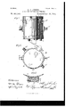
- My invention consists, also, in certain details and combinations hereinafter fully described and claimed, reference being had to the accompanying drawings, in which- Figure 1 is a side elevation of myimproved ladle.
- Fig. 2 is a top plan view of the same.
- Fig. 3 is a detail sectional view showing the rest and the slide therein.
- Fig. 5 is a sectional view. of the stopper, slide and connecting parts.
- a ladle in accordance with my invention, I employ a cylindrical ladle A, to which are suitably secured three legs a to rest on, and two trunnions a for carrying the ladle. I also employ two trunnions a for tilting the ladle to pour from the lip a should the opening in the bottom become stopped. up at any time.
- This ladle has a suitable fireproof lining at the sides and bottom, and in said bottom is made an opening B, through which the metal passes, said hole being arranged to one side of the center, so that it can be readily centered over a hole, and 'it also facilitates pouring from a large into a smaller ladle.
- a nozzle C is arranged in the opening or hole B, said nozzle being of a composition hereinafter described, and at the upper end is formed with a seat or recess 0, while at the lower end, below the ladle proper, 7o it'is provided with a nipple c, which increases its length, projects a steadier stream and permits the use of a thinner lining on the ladle bottom.
- a slide rest D is bolted to one side of the 7 ladle, said rest having a dove-tailed groove 5 extending throughout its entire length, and in said rest is held a vertical slide E which, atits upper end, is connected with the stopper F, within the ladle and is operated by means of a lever G to raise and lower said stopper.
- This stopper F comprises a small head f of graphite which fits in the seat or recess of the nozzle and closes the orifice of the same.
- a wrought iron 8 rod f which projects upward above the top of the ladle and carries near its upper end a cap or plate f and surrounding the rod between the cap and head is a protective covering f which prevents the rod getting so hot 0 that it will bend.
- V A horizontal rod or bar 11 is bolted to the top of the slide E and projects sufficiently inward to embrace the upper end of the rod f, and to do this, I slot the end of said bar, as shown at h.
- a ball-bearing I Surrounding the rod 5 f and seated upon the bar H, is a ball-bearing I, said bearing being essentially spherical in shape and having the flange i at its lower end which fits below the bar H, forming a rest therefor.
- An angled plate K is clamped to the bar H above the same, said plate being perforated to admit the passage of the rod f and recessed to form a seat for the upper end of the bearing I.
- a top nut L is screwed upon the upper end of the rod f and thus completes the connection between the slide E and stopper F.
- the lever G which operates the slide E, and in turn the stopper F, is pivoted to the rest D at g and at the extreme end is connected with the slide through the medium of a pitman M, which is slotted at the lower end to receive a pin on the end of said lever, and connected at its upper end with the slide E.
- the lever G is also connected with the slide by means of a pawl N mounted on the lever, near its pivot, and aratchet plate M, mounted upon the slide E.
- the object of this dual connection is to enable the operator to move the slide and stopper slowly at first and then rapidly as explained hereinafter.
- a stout spring 0 which bears upon the lug 0 upon the lower end of the slide, said spring encircling a rod 0', which is fastened to a lug 0 on the rest, and carries at its upper end a nut 0 against which the spring bears to hold the slide down.
- the ladle proper is preferably made of steel, while the rest and slide are made of cast iron, and between the rest and ladle I usually interpose a strip of asbestos, D, as shown in Fig. 5.
- the rod and connecting parts are preferably of wrought iron, and in the graphite head of the stopper is made a dove-tailed recess P, which is filled with sand and protects the end of the rod f
- the protective covering I prefer to make of a composition consisting of four parts molding sand, four parts ganister, and one part fire clay, as I have found this particularly adapted for the purpose.
- the parts are arranged as shown in Figs. 4 and 5, and the ladle is ready to receive its charge of molten metal.
- the spring 0 holds the stopper down in the nozzle and prevents the same from rising.
- the handle of the lever is thrown down. This brings the pawl N into action and being in engagement with the ratchet plate on the slide, said slide is moved upward slowly, inasmuch as the pawl is so close to the fulcrum of the lever.
- the slot in the end of the pitman permits this slow movement until the pin on the lever reaches the head of the slot. Then the rapid motion begins, and this pawl becomes disengaged, said pawl having aspring is, shown in dotted lines, Fig. 4, which throws the pawl outward as soon as the lever reaches This retarded motion, at;
- a stopperoperating mechaiiism comprising a slide arranged upon the exterior of the ladle,alever, pivoted also to said ladle, a pitman connected to said slide and also to the lever, a pawl connected to the lever adjacent to its fulcrum, a ratchet plate attached to the slide and a spring for returning said slide to its lower position, substantially as shown and described.
- An improved ladle having an opening in its bottom, a stopper for closing the same, a slide, a lever for operating the stopper connected with the slide at two points at different distances from the pivot of the lever, whereby said slide is given a differential movement, substantially as described.
- a protective covering for stopper rods consisting of four parts molding sand, four parts ganister and one part fire clay, in combination with a stopper and operating mechanism substantially as set forth.
Landscapes
- Engineering & Computer Science (AREA)
- Mechanical Engineering (AREA)
- Casting Support Devices, Ladles, And Melt Control Thereby (AREA)
Description
(No Model.) 2 Sheets-Sheet 1Q A. J. FISHER.
LADLE FOR GASTING GAR WHEELS.
No; 537,568. Patented Apr. 16, 1895.
a H W3 ii. i
II! l D H? d I A l a w xww ERS co, PNOTQLITHQ, wxsumemn n c Sheet 2.
gNo Model.) 2 Sheets A. J. FISHER. LADLE FOR CASTING GAR WHEELS. No. 537,568. Patented Apr. 16, 1895.
V///0 /W M 4 wn/n x W W 4 THE NORFUS Para; co. PHQTOLITHOH wAsmNnTQN. D c
' lllllllllllllll ALVA J. FISHER, OF CHICAGO, ILLINOIS, ASSIGNOR TOTHE GRIFFIN WHEEL COMPANY, OF SAME PLACE.
LADLE' FOR CASTING CAR-WH EELS.
$PECIFICATION' forming part of Letters Patent No. 537,568, dated April 16, 1895.
Application filed June 29,1894. Serial No. 516,073. (No model.)
To aZZ whom it may concern:
Be it known that I, ALVA J. FISHER, a citizen of the United States, residing in Chicago, in the county of Cook and State of Illinois, have invented certain new. and useful Improvements in Ladles for Casting Car-Wheels, of which the following is a full, clear, and exact description, reference being had to the accompanying drawings, forming a part of this specirs fication.
This invention is an improved ladle for casting car wheels and similar objects, one of the main features being that it pours from the bottom instead of from the top, as usual. I 5 The object of my invention is to provide a ladle of this description that will project a steady stream into the mold and one that can be readily centered above the mold.
Another object is to provide novel construc- 2o tions for the nozzle, stopper and operating parts, the said parts being so arranged that the stopper is first raised slowly and then rapidly so that the discharge of the melted metal will be retarded at first, a very essential feature in casting car wheels; and another object of my invention is to provide protective coverings for certain parts of the device whereby they are prevented from being burned out, and still another object is to so construct the stopper that the strain thereon will not be placed upon the rod, thus preventing said rod from being bent or upset.
With these various objects in view, my invention consists, broadly, in a ladle having 3 5 an opening in the bottom thereof, a stopper for closing the said opening and in the peculiar construction of the operating lever, whereby a retarded and accelerated motion of the stopper is acquired, and my invention 0 also includes a nozzle protective compound. My invention consists, also, in certain details and combinations hereinafter fully described and claimed, reference being had to the accompanying drawings, in which- Figure 1 is a side elevation of myimproved ladle. Fig. 2 is a top plan view of the same.
Fig. 3 is a detail sectional view showing the rest and the slide therein.
- vation showing the stopper-operating mech- Fig. 4 is an eleanism in detail. Fig. 5 is a sectional view. of the stopper, slide and connecting parts.
In constructing a ladle in accordance with my invention, I employ a cylindrical ladle A, to which are suitably secured three legs a to rest on, and two trunnions a for carrying the ladle. I also employ two trunnions a for tilting the ladle to pour from the lip a should the opening in the bottom become stopped. up at any time. This ladle has a suitable fireproof lining at the sides and bottom, and in said bottom is made an opening B, through which the metal passes, said hole being arranged to one side of the center, so that it can be readily centered over a hole, and 'it also facilitates pouring from a large into a smaller ladle. A nozzle C is arranged in the opening or hole B, said nozzle being of a composition hereinafter described, and at the upper end is formed with a seat or recess 0, while at the lower end, below the ladle proper, 7o it'is provided with a nipple c, which increases its length, projects a steadier stream and permits the use of a thinner lining on the ladle bottom.
A slide rest D is bolted to one side of the 7 ladle, said rest having a dove-tailed groove 5 extending throughout its entire length, and in said rest is held a vertical slide E which, atits upper end, is connected with the stopper F, within the ladle and is operated by means of a lever G to raise and lower said stopper. This stopper F comprises a small head f of graphite which fits in the seat or recess of the nozzle and closes the orifice of the same. Connected with this head f is a wrought iron 8 rod f which projects upward above the top of the ladle and carries near its upper end a cap or plate f and surrounding the rod between the cap and head is a protective covering f which prevents the rod getting so hot 0 that it will bend. V A horizontal rod or bar 11 is bolted to the top of the slide E and projects sufficiently inward to embrace the upper end of the rod f, and to do this, I slot the end of said bar, as shown at h. Surrounding the rod 5 f and seated upon the bar H, is a ball-bearing I, said bearing being essentially spherical in shape and having the flange i at its lower end which fits below the bar H, forming a rest therefor. An angled plate K is clamped to the bar H above the same, said plate being perforated to admit the passage of the rod f and recessed to form a seat for the upper end of the bearing I. A top nut L is screwed upon the upper end of the rod f and thus completes the connection between the slide E and stopper F.
The lever G which operates the slide E, and in turn the stopper F, is pivoted to the rest D at g and at the extreme end is connected with the slide through the medium of a pitman M, which is slotted at the lower end to receive a pin on the end of said lever, and connected at its upper end with the slide E. The lever G is also connected with the slide by means of a pawl N mounted on the lever, near its pivot, and aratchet plate M, mounted upon the slide E. The object of this dual connection is to enable the operator to move the slide and stopper slowly at first and then rapidly as explained hereinafter.
To hold the stopper and slide normally down, I provide a stout spring 0, which bears upon the lug 0 upon the lower end of the slide, said spring encircling a rod 0', which is fastened to a lug 0 on the rest, and carries at its upper end a nut 0 against which the spring bears to hold the slide down. The ladle proper is preferably made of steel, while the rest and slide are made of cast iron, and between the rest and ladle I usually interpose a strip of asbestos, D, as shown in Fig. 5. The rod and connecting parts are preferably of wrought iron, and in the graphite head of the stopper is made a dove-tailed recess P, which is filled with sand and protects the end of the rod f The protective covering I prefer to make of a composition consisting of four parts molding sand, four parts ganister, and one part fire clay, as I have found this particularly adapted for the purpose.
In operation, the parts are arranged as shown in Figs. 4 and 5, and the ladle is ready to receive its charge of molten metal. The spring 0 holds the stopper down in the nozzle and prevents the same from rising. When it is desired to discharge the contents into a mold, the handle of the lever is thrown down. This brings the pawl N into action and being in engagement with the ratchet plate on the slide, said slide is moved upward slowly, inasmuch as the pawl is so close to the fulcrum of the lever. The slot in the end of the pitman permits this slow movement until the pin on the lever reaches the head of the slot. Then the rapid motion begins, and this pawl becomes disengaged, said pawl having aspring is, shown in dotted lines, Fig. 4, which throws the pawl outward as soon as the lever reaches This retarded motion, at;
a certain angle.
first, permits a small stream to fiow through the ladle and then the increased motion permits a rapid discharge, the necessary arrangement in casting car Wheels and the like. When the stopper is elevated all the strain falls upon the top nut and bearing I, and when it is lowered the strain falls upon the bearing and the cap or plate, so that allcompression strain is taken from the rod f and it is thus prevented from bending or becoming upset.
Having thus described my invention, what I claim isg 1. An improved ladle, having an opening in its bottom, a stopper arranged in said ladle, a lever for operating said stopper, and means connected with the lever at difierent points beyond the fulcrum whereby a differential motion is imparted to the stopper, substantially as shown and described.
2. In a ladle, a stopperoperating mechaiiism comprising a slide arranged upon the exterior of the ladle,alever, pivoted also to said ladle, a pitman connected to said slide and also to the lever, a pawl connected to the lever adjacent to its fulcrum, a ratchet plate attached to the slide and a spring for returning said slide to its lower position, substantially as shown and described.
3. An improved ladle having an opening in its bottom, a stopper for closing the same, a slide, a lever for operating the stopper connected with the slide at two points at different distances from the pivot of the lever, whereby said slide is given a differential movement, substantially as described.
4. The combination of a ladle having an opening in its bottom, a stopper for closing the same, a slide and connections between the slide and stopper, and a lever pivoted upon the ladle and connected with the slide at its end and also at an intermediate point, substantially as set forth.
5. The combination of the ladle constructed as described, of the stopper located therein, the vertical slide arranged upon the exterior of the ladle, and connected at its upper end with the stopper, the operating lever arranged also upon the exterior of the ladle, the pitman having a slot at its lower end and connecting the lever and slide, the pawl pivoted to the lever and the ratchet plate secured to the slide, all arranged substantially as set forth and described.
6. The combination with the stopper having a central rod, of the slide, and horizontal bar attached thereto, the ball-shaped joint, angle plate and top nut, all arranged substantially as described.
'7. In a ladle, a protective covering for stopper rods consisting of four parts molding sand, four parts ganister and one part fire clay, in combination with a stopper and operating mechanism substantially as set forth.
8. In a ladle, the combination with the ladle proper, of the stopper arranged within the ladle the slide rest secured upon the exterior of the ladle, the slide operating therein and connected at its upper end with the stopper Within the ladle, the lever pivoted to the rest, a pitman connected with the slide and slotted at its lower end, a pin upon the end of the lever and resting in said slot, a pawl carried by the lever adjacent to the fulcrum and a ratchet plate secured to the slide and adapted for engagement with said pawl, substantially as set forth and described.
ALVA J. FISHER.
Witnesses:
CHAS. B. BOWEN, M. E. SHIELDS.
Publications (1)
| Publication Number | Publication Date |
|---|---|
| US537568A true US537568A (en) | 1895-04-16 |
Family
ID=2606329
Family Applications (1)
| Application Number | Title | Priority Date | Filing Date |
|---|---|---|---|
| US537568D Expired - Lifetime US537568A (en) | Alva j |
Country Status (1)
| Country | Link |
|---|---|
| US (1) | US537568A (en) |
Cited By (1)
| Publication number | Priority date | Publication date | Assignee | Title |
|---|---|---|---|---|
| US3028642A (en) * | 1958-08-28 | 1962-04-10 | Kaiser Aluminium Chem Corp | Apparatus for transfer of molten metal |
-
0
- US US537568D patent/US537568A/en not_active Expired - Lifetime
Cited By (1)
| Publication number | Priority date | Publication date | Assignee | Title |
|---|---|---|---|---|
| US3028642A (en) * | 1958-08-28 | 1962-04-10 | Kaiser Aluminium Chem Corp | Apparatus for transfer of molten metal |
Similar Documents
| Publication | Publication Date | Title |
|---|---|---|
| US537568A (en) | Alva j | |
| US521519A (en) | Pouring-ladle | |
| US1025438A (en) | Mold for casting circular objects. | |
| US1004548A (en) | Hot-metal car. | |
| US343872A (en) | Mold for casting | |
| US413727A (en) | Car-coupling | |
| US4581A (en) | Improvement in tuyeres | |
| US1251282A (en) | Hot-metal car. | |
| US958892A (en) | Mold. | |
| US459103A (en) | Sand mold | |
| US482689A (en) | James mcdermott | |
| US96131A (en) | Improvement in molding and casting pipe | |
| US1006606A (en) | Built-up ladle. | |
| US698565A (en) | Bottom-pouring ladle. | |
| US1207645A (en) | Ingot-mold. | |
| US518256A (en) | John la burt | |
| US544327A (en) | Sand-box | |
| US296369A (en) | Iviold for repairing broken rolls | |
| US1124576A (en) | Railroad switch-stand. | |
| US349050A (en) | Car-coupling | |
| US70482A (en) | John blake tare | |
| US1083121A (en) | Car-coupling. | |
| US633991A (en) | Ladle for casting car-wheels. | |
| US204450A (en) | Improvement in casting car-wheels | |
| US51192A (en) | Improved railroad turn-table |