US537356A - Rolling-mill - Google Patents
Rolling-mill Download PDFInfo
- Publication number
- US537356A US537356A US537356DA US537356A US 537356 A US537356 A US 537356A US 537356D A US537356D A US 537356DA US 537356 A US537356 A US 537356A
- Authority
- US
- United States
- Prior art keywords
- rollers
- bar
- bearings
- grooves
- shafts
- Prior art date
- Legal status (The legal status is an assumption and is not a legal conclusion. Google has not performed a legal analysis and makes no representation as to the accuracy of the status listed.)
- Expired - Lifetime
Links
Images



Classifications
-
- B—PERFORMING OPERATIONS; TRANSPORTING
- B21—MECHANICAL METAL-WORKING WITHOUT ESSENTIALLY REMOVING MATERIAL; PUNCHING METAL
- B21B—ROLLING OF METAL
- B21B13/00—Metal-rolling stands, i.e. an assembly composed of a stand frame, rolls, and accessories
- B21B13/08—Metal-rolling stands, i.e. an assembly composed of a stand frame, rolls, and accessories with differently-directed roll axes, e.g. for the so-called "universal" rolling process
- B21B13/12—Metal-rolling stands, i.e. an assembly composed of a stand frame, rolls, and accessories with differently-directed roll axes, e.g. for the so-called "universal" rolling process axes being arranged in different planes
Definitions
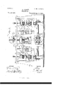
- the object of the invention is to provide a newand improved rolling mill,which is comparatively simple and durable in' construction, very effective in operation, and arranged to quickly and accurately roll the metal into a bar of the desired shape, in one single machine.
- Figure l is a plan View of the improvement.
- Fig. 2 is a side elevation of the'same.
- Fig. 3 is a longitudinal sectional elevation of the same,
- Fig. 4 is a transverse section of the same, on the line 4 4 of Fig. 2.
- Fig. 5 is an end View of part of the improvement; and
- Fig. 6 is a transverse section of the guideway between the sets of rollers, the section being taken on the line 6 6 of Fig. 3.
- the improved rolling mill is provided with a suitably constructed frame A, in the front end of which are journaled the transversely and horizontally extending rollers B, B', B2, arranged one above the other and forming one set of rollers.
- a similar set of transverselyextending horizontal rollers C, O', O2 is journaled in the rear end of the frame' A, and intermediate of the said sets of rollers B, B', B2 and C, C', C2, is arranged a set of vertically disposed rollers comprising the rollers D, D', D2, D3-
- rollers B and B' of the front set of horizontal rollers are formed with registering annular grooves B2 ⁇ and B4 respectively, into which the irn is first introduced through a feeding spout E, preferably made in sections, as indicated in Fig. 5, and supported in a transversely-extending support A', forming part of the frame A.
- the annular grooves D4, D5, are somewhat less in size than the first grooves B2, B4, so that the bar in passing through the set of rollers D, D', isagain reduced in size.
- This pair of registering grooves is less in size than the previous pair of grooves C2, C4, so that the metal is again reducedand passes through a longitudinally-extending guideway F2, to the vertically disposed rollers D', D2, to pass through a pair of registering annular grooves D, D7 i ⁇ n the said rollers D', D2.
- the bar then passes through a guideway F2 to annular grooves B5, B6 in the rollers B', B2, to then pass out over the support A', and be taken hold of by the operators and pass into a feed A spout E2, lheld on the said support A.
- the feed spout E2 delivers the reduced bar to a pair of grooves B6, B7 in the rollers B, B. Then the bar passes through a longitudinal guideway F4 to a pair of annular grooves D2, D9, in the rollers D2, D2, and then the bar passes through a guideway F5 to a pair of registering annular grooves in the rollers C, C', to be then discharged through the open frame A2.
- the longitudinally extending guideways F3 and F4 are held in transversely extending plates G supported on rods G2 erected in the sides of the main frame A.
- the other guideways F', F2, F5, are likewise held in a pair of plates G supported on .guide rods G2, similar to the guide rods G2.
- the bevel gear Wheel H2 will impart 'simultaneously a -rotarymotion'to the'bevel gear
- the bevel gear Wheels H3, H4, H5, H6, are each jotirnaled with their hubs in bearings N, held transversely adjustable on a bar H' secured in vthe sides of the main frame A, as illustrated inA Fig. 4, so that the operator is enabled to set the said gear Wheels properly in mesh with their 4corresponding gear Wheels L, L', L2 and L2, in case the size of the rollers D,D', D2, D3 is changed.
- the lower bearings for the rollers B, B', B2, B2 arey held in a'plate resting on the main frame A,while'the upper bearings' are held in a 4plate ⁇ P,"v'ertically ⁇ adjustable in” suitable guideways in the sidesof the frame A. ⁇ l In .order to] conveniently adj ust this'plate P vertically, Iy provide screw rods P', screwing in ⁇ the ends o'f the said plate, and mounted to -turn in suitablegbearings in thesides of the .fram-eA.
- One outer end of the shaft P4 is made square, as at P5, to permitthe operatorto app'lya Wrench orfother tooll for conveniently -turning the said shaft P4, to cause the Worms ⁇ Pato rotate thewormw'heels P2, and consequently the-screw rods P' to raise or lower the plate P as' 'the case may require, and according to' the direction in W'hiclrthe said shaft P4 is turned.”
- a rolling mill comprising a frame, the rollers B B B2 at the front of the frame, the rollers C C C2 at the rear of the frame, the rollers D D D2 D3 at about the center of the frame, the several series of rollers each being provided with three sets of annular registering grooves, the guide-Ways F F F2 Fa F4 and F5 between the several series of rollers, and means for simultaneously operating the said several series of rollers, substantially as described.
Landscapes
- Engineering & Computer Science (AREA)
- Mechanical Engineering (AREA)
- Metal Rolling (AREA)
Description
(No Model.) 4 sheets-sheet 1.
A. PERRY. ROLLING MILL.
No. 537,356. 1.5 s@ Pgtentedprl 9, 18915.
omda
By fr A TITOHNEYS.
(No Model.) 4 Shefats-Sheet 2. A. PERRY.
RULLING MILL. No. 537,356'. Patented Apr. 9, 1895.
l /NVE/VTOH www f@ A TTOHNES.
. (No Model.) 4 Sheets-Sheet 3.
A. PERRY.
ROLLING MILL.
No. 537,356. PatentedvApr. 9, 1895.
W/TNESSES:
/NVENTOH MMM@ A FORME-YS.-
(No Model.) 4 Sheets-Sheet 4.
A. PBR R Y. ROLLING MILL.
No. 537,356. v"'Paten'zeclApr. 9, 1895.
By WZD trios,
ATENT ARTHUR PERRY, OF MIDDLETOWN, NEW YORK.
ROLLING-MILL.
t5IRE('JIFIOA'IION,` forming part of Letters latent No. 537,356, dated April 9, 1895.
` application tied July 6, 1894.A` senti 516,736. (No mota.)
To a/ZZ whom it may concern.-
Be it known that I, ARTHUR PERRY, of Middletown, in the county of Orange and State of New York, have invented a new and Improved Rolling-Mill, of which the following is a full, clear, and exact description.
The object of the invention is to provide a newand improved rolling mill,which is comparatively simple and durable in' construction, very effective in operation, and arranged to quickly and accurately roll the metal into a bar of the desired shape, in one single machine. l
The invention consists in certain parts and details, and combinations of the same, as will be hereinafter fully described and then pointed out in the claims.
Reference is to be had to the accompanying drawings, forming a part of this specification, in which similar letters of reference indicate corresponding parts in all the views.
Figure l is a plan View of the improvement. Fig. 2 is a side elevation of the'same. Fig. 3 is a longitudinal sectional elevation of the same,
on the line 3=3 of Fig. l. Fig. 4 is a transverse section of the same, on the line 4 4 of Fig. 2. Fig. 5 is an end View of part of the improvement; and Fig. 6 is a transverse section of the guideway between the sets of rollers, the section being taken on the line 6 6 of Fig. 3. A
The improved rolling mill is provided with a suitably constructed frame A, in the front end of which are journaled the transversely and horizontally extending rollers B, B', B2, arranged one above the other and forming one set of rollers. A similar set of transverselyextending horizontal rollers C, O', O2, is journaled in the rear end of the frame' A, and intermediate of the said sets of rollers B, B', B2 and C, C', C2, is arranged a set of vertically disposed rollers comprising the rollers D, D', D2, D3-
The rollers B and B' of the front set of horizontal rollers are formed with registering annular grooves B2` and B4 respectively, into which the irn is first introduced through a feeding spout E, preferably made in sections, as indicated in Fig. 5, and supported in a transversely-extending support A', forming part of the frame A. The metal in passing through the grooves B2 and B4 of the revolv ing rollers B and B', is rolled into a shape corresponding to that of the grooves, and the bar thus formed passes through a guideway F, extending between the rollers B, B' and the rollers D, D', so that the bar after passing through the said guideway F, passes into the `registering grooves D4 and D5 in the rollers D, D. The annular grooves D4, D5, are somewhat less in size than the first grooves B2, B4, so that the bar in passing through the set of rollers D, D', isagain reduced in size. The bar after leaving the rollers D, D', passes through a second guideway F', which extends between the rollers D, D' and the rollers C, C' of the rear set of rollers, and the said guideway F' discharges the bar into a pair `of grooves C2, C4, see Fig. 3, so that the bar is again reduced, to nally pass through an open frame A2, and be taken hold of by the operator providedwith tongs or other means to take the bar andintroduce the same into a feed spout E supported on the said open frame A2, and discharging upon a pair of registering grooves C5 in the rollers C and C2. This pair of registering grooves is less in size than the previous pair of grooves C2, C4, so that the metal is again reducedand passes through a longitudinally-extending guideway F2, to the vertically disposed rollers D', D2, to pass through a pair of registering annular grooves D, D7 i`n the said rollers D', D2. The bar then passes through a guideway F2 to annular grooves B5, B6 in the rollers B', B2, to then pass out over the support A', and be taken hold of by the operators and pass into a feed A spout E2, lheld on the said support A.
The feed spout E2 delivers the reduced bar to a pair of grooves B6, B7 in the rollers B, B. Then the bar passes through a longitudinal guideway F4 to a pair of annular grooves D2, D9, in the rollers D2, D2, and then the bar passes through a guideway F5 to a pair of registering annular grooves in the rollers C, C', to be then discharged through the open frame A2. The longitudinally extending guideways F3 and F4 are held in transversely extending plates G supported on rods G2 erected in the sides of the main frame A. The other guideways F', F2, F5, are likewise held in a pair of plates G supported on .guide rods G2, similar to the guide rods G2.
It is understood that the several pairs of IOO ings in the main frame A is provided at onel end with a clutch H' for positively'connecting the said shaft H with the main shaft of the engine or other motor. The'shaft H' extends transversely in alignment; with the shafts for the rollers D, D',- D2, D2, as vvill be readily understood by reference to t'he'draw-y ings. l
On one side of the main frame A is secured a bevel-gear Wheel'H2-in mesh on "opposite sides with bevel gear'wh'eels I'and I', secured on shafts 12,13 `respectively,"extending"longil tudinally and'journaledv in suitable bearings asindicated inthe drawings.' "0n the'sh'afts I2, Pare secured' the bevel gear Wheels"I4,"I5,' in rmesh withl bevel' gear Wheels LI," J',respect ively secured on the'lower `ends of lthe vertically-disposed shafts J2,J2, respectively, jour'- naled in `suitable lbearings held' in brackets preferably made vertically adjustable in the mainframeA.
yOnv the' shaft J 2 are secured the bevel gear wheels J4, J5,"J6,"in mesh With the bevel gear Wheels-K, K', K2, respectively, secured onthe outer ends of the shafts `of ktlic rollers B, B', B2 respectively.v On thev other shaft J2 are securedsimilar bevel gear Wheels J7, .18,"59, in
mesh Wit-h bevel gear wheels K2, K4, K5', se cured onthe'outer ends of the shafts for the rollers C, C' andC2 respectively; Now, it will `be seen that when themain shaft H is rotated,
the bevel gear Wheel H2 will impart 'simultaneously a -rotarymotion'to the'bevel gear Thek Wheels 1,1', and 'their shafts l2 and'IS; rotary motionof the shafts l2and12 is transmitted by the gear Wheels I4,"I5fand bevel gear wheels J', J' tothe vertically 'disposed shafts J2,1J2, which by their gea-r Whe'els'J4,
respectivelygso that the front rollers B, B',
B2, and the rear rollers'G, C', C2, are 'rotated in unison, and 1n the proper direction, as indicated'by the arrows in Fig. 3, to cause the 2 teas@ rotated, the'bevel gear Wheels H2, H4, H5, H6, rotate simultaneously the gear Wheels L, L', L2, L2, and consequently the rollers D, D', D2 and D3 in `such a direction that the metal bar is passed forward and backward in the manner above indicated. Thus all the rollers in the three sets are rotated simultaneously Whenevertlie maindri'ving shaft H is set in motion. The bevel gear Wheels H3, H4, H5, H6, are each jotirnaled with their hubs in bearings N, held transversely adjustable on a bar H' secured in vthe sides of the main frame A, as illustrated inA Fig. 4, so that the operator is enabled to set the said gear Wheels properly in mesh with their 4corresponding gear Wheels L, L', L2 and L2, in case the size of the rollers D,D', D2, D3 is changed. When proper adjustment is made,`then the bearings Nare secured in position bysuitable set screWsN2.V The lower ends of the shafts' for the rollers D, D', D2, D3 are ]'urnaledf 7^in the said 'bearings N, and consequently' proper "alignment -can be ob- Vtainedlfo'r'the rollers by the'adju'stment of the bearings N. `In order to reduce the friction in the bearingsN, caused by thelatter'forming stepsfor the' Ashafts'of the rollers D, D', D2, D3, I provide the' upper e'ndsof they shafts of the said rollers with bearings O, each supported on a spring' O' secured to a trans'versely-extending bar 02, held in screWs'O3 screwing inl brackets O4 attachedto the sides of the main frame A. The lower bearings for the rollers B, B', B2, B2, arey held in a'plate resting on the main frame A,while'the upper bearings' are held in a 4plate`P,"v'ertically` adjustable in" suitable guideways in the sidesof the frame A.`l In .order to] conveniently adj ust this'plate P vertically, Iy provide screw rods P', screwing in `the ends o'f the said plate, and mounted to -turn in suitablegbearings in thesides of the .fram-eA. "0n theuppe'r ends ofl these verltic'alscrevv rods P', are secured the Worm wheels' P2, Vin vmesh with Worms'PS, held on a ltransverselysextending shaft P4 journaled in suitable bearings attached'to the main frame iA. One outer end of the shaft P4 is made square, as at P5, to permitthe operatorto app'lya Wrench orfother tooll for conveniently -turning the said shaft P4, to cause the Worms `Pato rotate thewormw'heels P2, and consequently the-screw rods P' to raise or lower the plate P as' 'the case may require, and according to' the direction in W'hiclrthe said shaft P4 is turned." "It will be yseen that by the arrangement de'- scribed, the entire machine 'is rendered'very compact, and the metal rolled into the bar does not require as much handling by operators' as is the casewith rolling mills as now constructed. It is'further understood that different" rollers having dierently shaped grooves"can"`be` inserted' so as to roll "metal into any desired shape, it being understood .that the graduated 'grooves in the several rollers are shaped,v accordingly.
/ Having thus vdescribed my invention, I
IOO
IiO
'claim as new and desire to secure by Let-ters Patent- 1. A rolling mill, comprising a frame, the rollers B B B2 at the front of the frame, the rollers C C C2 at the rear of the frame, the rollers D D D2 D3 at about the center of the frame, the several series of rollers each being provided with three sets of annular registering grooves, the guide-Ways F F F2 Fa F4 and F5 between the several series of rollers, and means for simultaneously operating the said several series of rollers, substantially as described.
2. In a rolling mill, the combination with a plurality of vertical rollers, of bearings for the upper ends of the said rollers, and springs secured to said bearings and to a support, substantially as and for the purpose set forth.
3. In a rolling mill, the combination with a series of vertical rollers, of bearings for the upper ends of the shafts of the said rollers, an adjustable bar, and springs secured to said bar and to the bearings, substantially as described. 4
4. In a rolling mill, the combination with verticalshafts, rollers thereon, and bevel gear wheels on the lower ends of the said shafts, of adjustable bearings, gear wheelsmounted in said bearings and meshing with the gear Wheels of the vertical shafts, and spring supported bearings for the upper ends of the said vertical shafts, substantially-as described.
ARTHUR PERRY.
Witnesses:
ABRAHAM CODDINGTON, n JAMES WRIGHT.
Publications (1)
| Publication Number | Publication Date |
|---|---|
| US537356A true US537356A (en) | 1895-04-09 |
Family
ID=2606117
Family Applications (1)
| Application Number | Title | Priority Date | Filing Date |
|---|---|---|---|
| US537356D Expired - Lifetime US537356A (en) | Rolling-mill |
Country Status (1)
| Country | Link |
|---|---|
| US (1) | US537356A (en) |
-
0
- US US537356D patent/US537356A/en not_active Expired - Lifetime
Similar Documents
| Publication | Publication Date | Title |
|---|---|---|
| US537356A (en) | Rolling-mill | |
| US694722A (en) | Machine for rolling metal forms. | |
| US1408791A (en) | Machine for straightening pipes, rods, and the like | |
| US127436A (en) | Improvement in machines for twisting metal | |
| US511422A (en) | Rolling-mill | |
| US113708A (en) | Improvement in rolls for rolling hoop, bar, and rod-iron | |
| US103397A (en) | Improved machine for rolling metals | |
| US1133551A (en) | Rolling-mill. | |
| US118188A (en) | Improvement in machines for crushing corn | |
| US156162A (en) | Improvement in rubber-cutting machines | |
| US420100A (en) | Rolling-mill | |
| US209829A (en) | Improvement in roller-mills for reducing grain | |
| US617197A (en) | Screen | |
| DE2233923C3 (en) | Ball mill for processing used foundry molding sand | |
| US725157A (en) | Adjustable bench for rolls. | |
| US267432A (en) | Fbank a | |
| US269404A (en) | Pulverizing-machine | |
| USRE7168E (en) | Improvement in grain-separators | |
| US7397A (en) | Machinery | |
| US267983A (en) | Lbvi j | |
| JP2002066615A (en) | Guideless rolling mill row | |
| US841427A (en) | Work-reversing mechanism for rolling-mills. | |
| US24434A (en) | Improvement in corn-harvesters | |
| US327728A (en) | Rolling-mill | |
| US594482A (en) | medart |