US537199A - Electric-railway supply system - Google Patents
Electric-railway supply system Download PDFInfo
- Publication number
- US537199A US537199A US537199DA US537199A US 537199 A US537199 A US 537199A US 537199D A US537199D A US 537199DA US 537199 A US537199 A US 537199A
- Authority
- US
- United States
- Prior art keywords
- section
- magnet
- car
- armature
- sections
- Prior art date
- Legal status (The legal status is an assumption and is not a legal conclusion. Google has not performed a legal analysis and makes no representation as to the accuracy of the status listed.)
- Expired - Lifetime
Links
Images
Classifications
-
- B—PERFORMING OPERATIONS; TRANSPORTING
- B60—VEHICLES IN GENERAL
- B60M—POWER SUPPLY LINES, AND DEVICES ALONG RAILS, FOR ELECTRICALLY- PROPELLED VEHICLES
- B60M1/00—Power supply lines for contact with collector on vehicle
- B60M1/02—Details
- B60M1/10—Arrangements for energising and de-energising power line sections using magnetic actuation by the passing vehicle
- B60M1/103—Arrangements for energising and de-energising power line sections using magnetic actuation by the passing vehicle by vehicle-borne magnets
Definitions
- My present invention relates more particularly to that class of electric railways in which the working contact or conductor from which the car takes up current is divided into separate sections or contacts that are automatically charged as the car reaches the section and discharged as the car leaves it by means of suitable electric switches that are normally open and when closed connect the said section or working conductor with a suitable supply wire or circuit leading from a proper source of energy.
- My invention relates more particularly to those systems wherein a magnet on the car operates upon an armature on the permanent way as the car moves along, and by actuating said armature operates the switch that closes the connection between a supply or line conductor and the insulated working conductor 'or section of conductor.
- two magnets were employed of respectively opposite polarity, one of which closes and the other of which opens the switch thus requiring a reversal of the polarity of said magnets in order to reverse the direction of travel of the car.
- My inventionadmits of thecar running in either direction without reversing the polarity of the magnet or magnets employed, either of which when two are used may serve'to set the switches instead of one setting and the other unsetting.
- My invention consists in the combination with amagnet on" the car and an armature therefor on the permanent way for closing the switch for one section, of means for opening the switch by current flowing to another section when the car reaches the latter.
- My invention consists further in the combination of the magnet on the car, a polarized armature and switch for one section, and an electro-magnet for reversing the position of the polarized armature, said electro magnet being in the circuit of another section.
- My invention consists also in the combinaebruary 2, 1895. Seria1No. 11 'l- (Nomodem tion with each section, of a resetting circuit closed therethrough for sections both to the front and rear of said section.
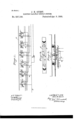
- Figure 1 is a general diagram illustrating the principle of my invention.
- Fig. 2 is an inverted plan view of the cover plate for the box containing the switch for one section of working conductor.
- Fig. 3 is a side elevation showing more in detail the switch for one section and the arrangement of magnets and current collector on the car.
- A is one of the sections of working conductors.
- This may be and preferably is the cover of a box or section of conduit containing the switches, armatures and coils on the permanent way.
- the cover may be of iron and flush with the surface of the roadway or otherwise located to be engaged by a current collector borne by the car.
- the current collector is typified at W, as'a wheel working in a frame or bracket supported from above by any part of the car or car truck and adapted to pick up the curreutrforoperating the motor or other devices on the car.
- the sections of working conductor preferably, lap upon one another at their abutting ends, as shown in the plan Fig. 2, so that there shall be no break of electrical continuity in the passage of the wheel W, across the joints where the ends of the sections are insulated from one another.
- the circuit closer is an-armature permanentlyor continuously magnetized and serving when actuated by either of the magnets B, on the car, to operate the circuit closer whichconn'ects the section of working conductor to the supply line L, Fig. 1.
- the circuit closer may be the armature itself which is pivotally supported at one end on the pole of an electro-magnet E, and at its free end engages, when raised with a part in electrical connection with the plate A, thus closing the electrical con nection to the supply wire by way of the support for the armature coil 20, for electro-magnet E, and wire m.
- the coil 21, or 22 operates through the core of electro-magnet E,orotherwise, with proper polarity to pull down the armature ll, whose free N-polar end is arranged as shown over the S-pole of electromagnet E, but is kept out of actual contact therewith by interposed nonmagnetic material F.
- Electromagnets E also serve to hold the armatures down and prevent them from being accidentally drawn up by their own magnetism when subjected to heavy vibration or jamming.
- the direction of the current in the several coils is indicatedby the arrow heads.
- On the under side of the plate A are strips of soft iron g, g, connected to plugs C, also of soft iron which serve to carry the magnetism of magnets B, through the cover plate and by strips g, localize it over the free polar end of the armature H.
- the plugs O are preferably set in bushings O, of non-magnetic material like brass to prevent dissipation of the magnetism in the cover plate A, of iron.
- the free ends of the strips 9, 9, may be supported by brass rivets or pins a.
- Two magnets B are shown and both may be energized at the same time from the circuit on the car in any desired way and both have like poles presented to the armatures. If the caris proceeding in the direction of the arrow the one at the left is the one that operates. In moving in the opposite direction, the other operates. It is obvious that while proceeding in one direction the rear magnet might be rendered inactive, if desired.
- R is any source of electric power
- T the rail or conductor between which and main line L, the connection is completed and broken section by section as the car proceeds in either direction. Six sections of working conductor are shown.
Landscapes
- Engineering & Computer Science (AREA)
- Mechanical Engineering (AREA)
- Train Traffic Observation, Control, And Security (AREA)
Description
, UNITED S'rn'rns PATENT Grates.
JOHN H. GUEST, OF BOSTON, MASSACHUSETTS.
ELECTRIC-RAILWAY SUPP LY SYSTEM.
SPECIFICATION forming part of Letters Patent No. 537,199, dated April 9, 1895.
Application filed February 20, 1894. Renewed I To all whom it may concern.-
Be it known that 1, JOHN H. GUEST, a citizen of the United States, and a resident of Boston, in the county of Suffolk and State of Massachusetts, have invented a certain new and useful Improved Electric Railway, of which the following is a specification.
My present invention relates more particularly to that class of electric railways in which the working contact or conductor from which the car takes up current is divided into separate sections or contacts that are automatically charged as the car reaches the section and discharged as the car leaves it by means of suitable electric switches that are normally open and when closed connect the said section or working conductor with a suitable supply wire or circuit leading from a proper source of energy.
My invention relates more particularly to those systems wherein a magnet on the car operates upon an armature on the permanent way as the car moves along, and by actuating said armature operates the switch that closes the connection between a supply or line conductor and the insulated working conductor 'or section of conductor. In the plansheretofore proposed two magnets were employed of respectively opposite polarity, one of which closes and the other of which opens the switch thus requiring a reversal of the polarity of said magnets in order to reverse the direction of travel of the car.
My inventionadmits of thecar running in either direction without reversing the polarity of the magnet or magnets employed, either of which when two are used may serve'to set the switches instead of one setting and the other unsetting.
My invention consists in the combination with amagnet on" the car and an armature therefor on the permanent way for closing the switch for one section, of means for opening the switch by current flowing to another section when the car reaches the latter.
My invention consists further in the combination of the magnet on the car, a polarized armature and switch for one section, and an electro-magnet for reversing the position of the polarized armature, said electro magnet being in the circuit of another section.
My invention consists also in the combinaebruary 2, 1895. Seria1No. 11 'l- (Nomodem tion with each section, of a resetting circuit closed therethrough for sections both to the front and rear of said section.
My invention consists further in the special combinations of devices and apparatus hereinafter described, and more particularly stated in the claims.
In the accompanying drawings:-Figure 1 is a general diagram illustrating the principle of my invention. Fig. 2 is an inverted plan view of the cover plate for the box containing the switch for one section of working conductor. Fig. 3 is a side elevation showing more in detail the switch for one section and the arrangement of magnets and current collector on the car.
I will refer first to the devices shown in Fig. 3, promising that the devices themselves may be indefinitely varied inform and construction, the gist of'the invention consisting in the combination of circuits and devices each adapted to operate electrically and magnetically as required in the combination.
A, is one of the sections of working conductors. This may be and preferably is the cover of a box or section of conduit containing the switches, armatures and coils on the permanent way. The cover may be of iron and flush with the surface of the roadway or otherwise located to be engaged bya current collector borne by the car. The current collector is typified at W, as'a wheel working in a frame or bracket supported from above by any part of the car or car truck and adapted to pick up the curreutrforoperating the motor or other devices on the car. The sections of working conductor, preferably, lap upon one another at their abutting ends, as shown in the plan Fig. 2, so that there shall be no break of electrical continuity in the passage of the wheel W, across the joints where the ends of the sections are insulated from one another.
H, is an-armature permanentlyor continuously magnetized and serving when actuated by either of the magnets B, on the car, to operate the circuit closer whichconn'ects the section of working conductor to the supply line L, Fig. 1. The circuit closer may be the armature itself which is pivotally supported at one end on the pole of an electro-magnet E, and at its free end engages, when raised with a part in electrical connection with the plate A, thus closing the electrical con nection to the supply wire by way of the support for the armature coil 20, for electro-magnet E, and wire m. Other connections are at the same time established by way of the core of the magnet E, and wire or, to the same supply wire through coils 21, 22, of magnets E, at other sections removed; in the present case two or other number of sections to the front and rear of the active section. The otlice of the coils 21, 22, is to reset the switches of other sections, when set, to the normal position or position opposite that in which they are placed by the action of a magnet B. The office of the coil 20, is to strongly polarizethe armature II, and insure good connection of the circuit closure. 'The armature H, is preferably of steel. The coil 21, or 22, operates through the core of electro-magnet E,orotherwise, with proper polarity to pull down the armature ll, whose free N-polar end is arranged as shown over the S-pole of electromagnet E, but is kept out of actual contact therewith by interposed nonmagnetic material F. Electromagnets E, also serve to hold the armatures down and prevent them from being accidentally drawn up by their own magnetism when subjected to heavy vibration or jamming.
The direction of the current in the several coils is indicatedby the arrow heads. On the under side of the plate A, are strips of soft iron g, g, connected to plugs C, also of soft iron which serve to carry the magnetism of magnets B, through the cover plate and by strips g, localize it over the free polar end of the armature H. The plugs O, are preferably set in bushings O, of non-magnetic material like brass to prevent dissipation of the magnetism in the cover plate A, of iron. The free ends of the strips 9, 9, may be supported by brass rivets or pins a.
Two magnets B, are shown and both may be energized at the same time from the circuit on the car in any desired way and both have like poles presented to the armatures. If the caris proceeding in the direction of the arrow the one at the left is the one that operates. In moving in the opposite direction, the other operates. It is obvious that while proceeding in one direction the rear magnet might be rendered inactive, if desired.
In the diagram Fig. 1, R, is any source of electric power, and T, the rail or conductor between which and main line L, the connection is completed and broken section by section as the car proceeds in either direction. Six sections of working conductor are shown.
The general operation is as follows:-Assuming that thecar is moving from right to left, and that the magnet B, thereon passes onto section 4, the collector being in connection with section 5, next in the rear, when the magnet reaches the first plug 0, it magnetizes the same and through the soft iron strip g, acts 011 the permanent magnet H, thereby closing the connections for section 4, so that when the collector reaches said section the latter will be alive. lVhen circuit is closed at 4, by the collector reaching said section, which it immediately does, current flows also by way of its circuit closer through a coil 21, of section 6, and a coil 22 of section 2, and in such direction that the armature of the scction is positively moved downward by the action of electro-magnet E, and is thereby pulled away from contact with the soft iron g, against which it was held by permanent magnetism although the collector had left section 6, and thereby broken the connection of coil 20 at such section. At section 2, no effect will be produced unless the armature shall have been accidentally raised or unless the car shall have leftsaid section in proceeding in the opposite direction. The attraction of armature H, at section 4, and the contact of the collector with the working conductor, as just stated, also bring into action the coil 20, which operates to insure the continuance of the switch in circuit closing position while the car is passing on the section, and also gives the steel magnet a permanent charge which keeps it up until positively drawn down again by the action of coil 21, when the car reaches section 2. As will be seen the collector in leaving section 5, breaks no electric ci ris reset by the current which flows to it from the working conductors of section 3, and through the coil on magnet E, and the coil of magnet. E, at section 1, is also rendered active. In proceeding in the opposite direction the same operation takes place, the closing of the circuit at each section serving to render active the coils of sections at front and rear by which the switches are positively opened. These sections may, obviously, be separated by one or a greater number of sections, as desired, from the section from which the car is taking current. Under this system each car will positively control sections both at front and rearof itself and cannot be approached by another car nearer than the distance covered by the controlled and anyintermediate sections. This action would be useful undersome conditions thoughIcontemplate in general the use of short sections and the having of a few only active at the same time. In moving in the opposite direction the other magnet B, which now becomes the forward magnet operates on the armatures to close the circuits and the coil of magnets E, which were rendered active ahead of the car now operate behind it to resetthe circuit closers to normal position.
I do not limit myself to any particular construction of circuit closing devices or ways of arranging the several magnets and the armatures on the permanent Way. Thus the coils 21, 22, might operate on the circuit closer in any other desired way to rest it though I prefer to have these act by means of a core E, upon the polarized armature H. It will be obvious further that it is not material whether thearmature operate by repulsion or by attraction in passing from either position to the of the apparatus. So also the magnet B, could be made to act upon the armature on the permanent way through other constructions or arrangements of intermediate soft iron pieces or such pieces might be even dispensed with.
What I claim as my invention is 1. The combination with a magnet on the car and an armature therefor on the permanent way for closing the switch for one section, of a resetting magnet on the permanent 3. The combination with each section, of
working conductor, of resetting circuits closed simultaneously to sections both to the front and rear of said section and including at each such section the coils of an unsetting electromagnet.
4c. The combination with a section of working conductor and a polarized circuit closer therefor, of an actuating'magnet on the vehicle for setting the circuit closer, and an unsetting magnet connected with sections at both sides thereof.
5. The combination, with a section of working conductor, of a circuit closer, a polarized armature for actuating the same by the influence of a magnet on the car, an energizing coil for said armature in the circuit to said section, and a coil on the permanent way in a connection closed by the switch of another section for acting on said polarized armature so as to open the circuit closer.
6. The combination with the working sections and switches therefor having armatures operated by a magnet on the car, of restoring magnets operating on said armatures and having two coils connected respectively to sections to front and rear.
JOHN H. GUEST.
Witnesses:
NELSON L. MARTIN, HOMER ALBERs.
Publications (1)
| Publication Number | Publication Date |
|---|---|
| US537199A true US537199A (en) | 1895-04-09 |
Family
ID=2605960
Family Applications (1)
| Application Number | Title | Priority Date | Filing Date |
|---|---|---|---|
| US537199D Expired - Lifetime US537199A (en) | Electric-railway supply system |
Country Status (1)
| Country | Link |
|---|---|
| US (1) | US537199A (en) |
-
0
- US US537199D patent/US537199A/en not_active Expired - Lifetime
Similar Documents
| Publication | Publication Date | Title |
|---|---|---|
| US537199A (en) | Electric-railway supply system | |
| US493623A (en) | Ments | |
| US781993A (en) | Circuit-closer. | |
| US565985A (en) | Underground-trolley system | |
| US537197A (en) | Supply system for electric railways | |
| US625512A (en) | Robert lundell | |
| US389822A (en) | Sylvania | |
| US915238A (en) | Electric road-crossing signal. | |
| US579760A (en) | Electric railway | |
| US646229A (en) | Surface-contact system of electric railways. | |
| US669218A (en) | Electric railway. | |
| US1852210A (en) | Polarized relay | |
| US776371A (en) | Electrical-railway system. | |
| US439428A (en) | Electric railway | |
| US480850A (en) | Electric railway | |
| US534642A (en) | Railway supply system | |
| US591706A (en) | David urquhart and frank wynne | |
| US948374A (en) | Electric-motor-controlling device. | |
| US607610A (en) | Electric-railway system | |
| US566801A (en) | Electric-railway system | |
| US537195A (en) | Conduit electric railway | |
| US765212A (en) | Electromagnetic block system of control. | |
| US549129A (en) | Railway-switch | |
| US1736397A (en) | System of train control | |
| US537416A (en) | Supply system for electric railways |