US5368317A - Fire truck torque box chassis frame - Google Patents
Fire truck torque box chassis frame Download PDFInfo
- Publication number
- US5368317A US5368317A US08/005,374 US537493A US5368317A US 5368317 A US5368317 A US 5368317A US 537493 A US537493 A US 537493A US 5368317 A US5368317 A US 5368317A
- Authority
- US
- United States
- Prior art keywords
- box
- members
- torque box
- rigid
- elongated
- Prior art date
- Legal status (The legal status is an assumption and is not a legal conclusion. Google has not performed a legal analysis and makes no representation as to the accuracy of the status listed.)
- Expired - Lifetime
Links
Images

Classifications
-
- E—FIXED CONSTRUCTIONS
- E06—DOORS, WINDOWS, SHUTTERS, OR ROLLER BLINDS IN GENERAL; LADDERS
- E06C—LADDERS
- E06C5/00—Ladders characterised by being mounted on undercarriages or vehicles Securing ladders on vehicles
- E06C5/02—Ladders characterised by being mounted on undercarriages or vehicles Securing ladders on vehicles with rigid longitudinal members
- E06C5/04—Ladders characterised by being mounted on undercarriages or vehicles Securing ladders on vehicles with rigid longitudinal members capable of being elevated or extended ; Fastening means during transport, e.g. mechanical, hydraulic
-
- A—HUMAN NECESSITIES
- A62—LIFE-SAVING; FIRE-FIGHTING
- A62C—FIRE-FIGHTING
- A62C27/00—Fire-fighting land vehicles
-
- B—PERFORMING OPERATIONS; TRANSPORTING
- B62—LAND VEHICLES FOR TRAVELLING OTHERWISE THAN ON RAILS
- B62D—MOTOR VEHICLES; TRAILERS
- B62D21/00—Understructures, i.e. chassis frame on which a vehicle body may be mounted
Definitions
- the invention pertains to vehicle torque box chassis frames for supporting extendible aerial ladders, such a frame being particularly useful with firefighting vehicles.
- Firefighting vehicles such as ladder trucks include extendible aerial ladders whereby the ladders may be raised and extended in excess of one hundred feet, as may be required in fighting fires in multiple story buildings, or conducting rescues therefrom.
- extending aerial ladders are hydraulically operated whereby the ladder assembly may be lowered to a stored position, and raised to an operative position.
- the ladder system consists of a plurality of extension ladders, and when the ladders are extended, and partially raised, significant bending forces are applied to the frame of the support vehicle due to the weight of the ladders, and any personnel or equipment supported thereon.
- jack systems In order to stabilize vehicles supporting extendible ladder systems, it is common to mount jack systems upon the vehicles which extend laterally from the vehicle sides and include hydraulically extendible jacks for engagement with the ground to stabilize these vehicles during ladder extension.
- Most jack systems are attached to the conventional vehicle structure, including the suspension system, and while such jack systems do greatly improve the vehicle stability during aerial ladder extension due to the high centroidal moment of inertia imposed upon the vehicle by an extended aerial ladder, the ultimate degree of stability desired has not been achievable, and the height of extendible aerial ladders has been limited due to the inability to provide as stable a ladder platform as possible.
- Another object of the invention is to provide an integral aerial torque box vehicle chassis free which includes a turntable support for aerial ladders wherein extendible jack structure is integrally formed with the torque box whereby the torque box may be directly supported upon the ground without influence from the vehicle suspension system.
- Yet another object of the invention is to provide an integral aerial torque box vehicle chassis frame constituting a platform for extendible ladders wherein the torque box is supported upon integral jack structure to provide stability, and the torque box is open having an accessible rear end wherein ladders may be stored within the torque box at a readily accessible location and height.
- An additional object of the invention is to provide an integral aerial torque box vehicle chassis frame which may be readily fabricated using conventional metal fabricating apparatus.
- a pair of spaced parallel heavy duty channel members are used to form the lower region of the torque box, while a pair of elongated box cross section members are vertically disposed above the channel members a significant distance to provide sufficient resistance to bending moments.
- Bracing elements in the form of sheet steel are interposed between the upper and lower box and channel members located on a common side of the box, while the lower channel members are interconnected by a sheet steel bracing floor member.
- the upper members are preferably interconnected by obliquely disposed truss members who ends are welded to the upper members.
- the rear end of the torque box constitutes a turntable support for the aerial ladder apparatus.
- the turntable support is integral with the other components of the torque box and includes a plurality of columns having a box transverse cross section for supporting the weight of the ladder assembly without deflection.
- the turntable support defines the rear end of the torque box, and is open in alignment with the length of the torque box chassis frame whereby the interior of the torque box is accessible through the turntable support and may serve as a chamber to receive ladders, or other equipment.
- the torque box chassis frame includes jack receiving tubes for supporting hydraulic jacks.
- the front pair of the jack supporting tubes is located adjacent the front region of the torque box below the channel men,hers, while the rear pair of jack receiving tubes is located below the turntable support.
- the jack tubes are of a length perpendicularly disposed to the length of the torque box, and the jack structure arms located therein are capable of being laterally extended relative to the torque box length whereby the hydraulic jacks formed on the ends of the extendible arms may be lowered to engage the ground and directly support the torque box chassis upon the terrain.
- the support of the torque box on the terrain by the jacks bypasses the vehicle suspension, and actually raises the vehicle slightly with respect to the terrain whereby, during ladder operation, the entire vehicle may be supported upon the jacks.
- a torque box chassis frame constructed in accord with the invention achieves a rigidity not heretofore attained, and provides a platform for an extendible aerial ladder assembly which permits aerial ladders to be extended to heights not previously possible.
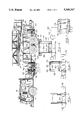
- FIG. 1 is a side elevational view of a firefighting vehicle utilizing the torque box chassis frame of the invention, the extendible ladder assembly being partially illustrated,
- FIG. 2 is a side elevational view of the torque box chassis frame, per se,
- FIG. 3 is a plan view of the torque box chassis frame of FIG. 2,
- FIG. 4 is an elevational sectional view as taken along Section 4--4 of FIG. 3,
- FIG. 5 is an elevational sectional view as taken along Section 5--5 of FIG. 3,
- FIG. 6 is an elevational sectional view as taken along Section 6--6 of FIG. 3, and
- FIG. 7 is a plan sectional view as taken along Section 7--7 of FIG. 2.
- FIG. 1 The overall environment of a fire truck torque body in accord with the invention is best represented in FIG. 1 wherein an entire fire truck vehicle is illustrated.
- the fire truck basic component is the frame or chassis 10 much of which forms the torque box construction of the invention.
- the frame is supported on front wheels 12 and dual rear wheels 14 which are attached to the frame 10 by conventional suspension structure 16 which may be formed by leaf springs, torsion springs or air bags, as is well known in the art.
- the truck cab 18 is located at the front end of the frame 10 and includes the engine and other vehicle control components, as well as providing an enclosure for the firemen during transportation.
- the usual pump structure 20 may be mounted upon the frame 10, and other apparatus may be mounted upon the truck frame as is commonly used with firefighting equipment.
- an extendible ladder 22 is pivotally mounted upon the bracket 24 which is attached to the turntable 26 rotatably supported upon the torque box by conventional bearings, not shown.
- the vertical elevation of the ladder 22 is controlled by the extendible hydraulic cylinder 28 interposed between the bracket 24 and the ladder structure, as well known.
- extendible ladder utilized with fire trucks employing the invention does not form a part of the invention, and conventional ladder arrangements may be used except that trucks utilizing the torque box of the invention may employ ladders of greater extendible length, and a greater number of sections, than extendible ladder assemblies previously employed with mobile fire truck platforms.
- the frame 10 includes a section thereof designated as a torque box 30, the torque box constituting that portion of the vehicle frame upon which the majority of bending forces are imposed when the ladder 22 is extended.
- the basic components of the frame 10 are a pair of substantially parallel channel members 32 which extend the length of the vehicle.
- the members 32 are in spaced relationship to each other and the wheels 12 and 14 are located below the members 32 and support the members through the wheel suspension apparatus.
- Vertical bracing colons 36 are interposed between the members 32 and 34 as being welded thereto, and the lateral sides of the torque box 30 are defined by a sheet metal plate 38 extending between the members 32 and 36 at each side of the torque box and the metal plate 38 is welded to the members 32 and 34, as well as to the columns 36.
- the sheet metal plate 38 rigidly interconnects the members 32 and 34 in a vertical direction, and the columns 36 which are also welded to the plate 38 prevent the plate 38 from buckling.
- a sheet metal bottom plate 40, FIGS. 5 and 6, extends between the upper ends of the channel members 32 wherein the plates 38 and plate 40 define a U-shaped configuration closing in the sides and bottom of the torque box 30.
- the upper portion of the torque box is defined by a plurality of truss bracing members 42, FIG. 3, which extends between the box members 34 having shaped ends whereby the men%bets 42 are welded to the box members 34.
- the torque box 30 is now defined of a rectangular cross sectional configuration having the lateral side bracing plates 38, the bottom plate 40, and the upper truss bracing members 42.
- the torque box 30 At its front end the torque box 30 is defined by wedge shaped plates 44 extending from the box members 34 to the upper edges of the channel members 32, and the plates 44 are welded to the associated structure to further define an integral assembly.
- the torque box 30 is defined by the ladder turn table support 46.
- the turn table support 46 is defined by lateral sheet plate sides 48 located between four steel box beam columns 50, FIG. 7, welded to the channel members 32 and extending thereabove.
- the plate sides 48 are also welded to the columns 50, and the columns 50 are also welded to the plates 38.
- the turn table support 46 includes a rectangular frame 52 formed of steel box beams, and a thick two inch steel plate 54 having the circular opening 56 is welded to the upper turn table frame 52.
- the turn table support 46 constitutes an integral rear end of the torque box 30 so that all forces imposed upon the ladder turn table support 46 will be directly imposed upon the torque box 30.
- the ladder support structure is mounted upon the plate 54 and extends into the opening 56, and such support structure may include bearings, a large gear, motor, and other apparatus for rotating the ladder turn table 26.
- the jacks are mounted within outrigger supports of a rectangular configuration for supporting the jack structure.
- the outrigger support tubes are best illustrated in FIGS. 2 and 3.
- a pair of front or forward jack support tubes 58 are welded to the underside of the channel members 32 at a location directly below the wedge plates 44.
- the tubes 58 are of an elongated configuration as will be appreciated from FIG. 3, and the length thereof is at right angles to the length of the torque box and channel members 32.
- the rear jack tubes 60 are also welded to the underside of the channel members 32, and are located directly below the turntable support 46. Bracing fillets 62 may be interposed between the jack tubes and the channel members 32 to prevent twisting or displacement of the jack tubes.
- Hydraulic jack arm structure of a known type generally represented at 64 is supported within the front tubes 58, and at their outer ends the jacks include vertically disposed hydraulic cylinders 66 having pistons supporting a foot pad which engages the terrain.
- the jack arms located within the front tubes 58 extend in an outrigger manner in opposite directions from the torque box 30 to provide lateral support of the front portion of the torque box in either direction.
- jack arm structure 68 is located within the rear tubes 60 and include cylinders 70 having foot pads located at the lower end of the cylinder pistons for engaging the terrain, the jack arms 68 being extendible in opposite directions from the torque box 30 in the same manner as the front jacks 64.
- a pair of front drop and lock jacks 74 are rigidly mounted on frame 10 by brace gussets 76 which are vertically adjusted by cylinders 78.
- the vertical height of the torque box plates 38 is approximately thirty-six inches, and the separation of the channel members 32 and box members 34 is approximately 36 inches, while the separation of the channel members 32 is of substantially equal dimension, and as the plates 38, the bottom 40, and the truss bracing members 42, as well as the turn table support sides 48, columns 50 and frame 52 all define a large hollow box beam, the torque box 30 is capable of withstanding very high bending forces with minimal deformation as imposed thereon by the weight of the ladder assembly 22.
- the jacks 64, 68 and 74 are directly connected to the torque box 30 the support of the torque box and ladder assembly is directly by the terrain, and the vehicle suspension is bypassed and is not a part of the ladder support. Accordingly, the torque box 30 is directly supported upon the terrain and as the jacks 64 and 68 can be longitudinally laterally extended within their tubes 58 and 60, respectively, a wide, rigid, broad base support for the torque box 30 is provided.
- the extension of the cylinders 66, 70 and 78 may actually lift the rear wheels 14, and/or front wheels 12, from the terrain, depending upon the degree of the grade.
- the weight of the vehicle frame 10 will be supported by the wheels and their associated suspensions.
- the configuration of the torque box 30 is such that a rectangular space 72, FIG. 6, is located between the plates 38 and above the bottom plate 40, and this space is open at the rear through the turn table support 46 whereby ladders, hose, or other equipment may be readily stored within the space 72 of the torque box 30, and easily and rapidly removed therefrom for use.
Landscapes
- Engineering & Computer Science (AREA)
- Mechanical Engineering (AREA)
- Chemical & Material Sciences (AREA)
- Combustion & Propulsion (AREA)
- Transportation (AREA)
- Health & Medical Sciences (AREA)
- Public Health (AREA)
- Business, Economics & Management (AREA)
- Emergency Management (AREA)
- Forklifts And Lifting Vehicles (AREA)
- Ladders (AREA)
- Body Structure For Vehicles (AREA)
Abstract
Description
Claims (5)
Priority Applications (3)
| Application Number | Priority Date | Filing Date | Title |
|---|---|---|---|
| US08/005,374 US5368317A (en) | 1993-01-15 | 1993-01-15 | Fire truck torque box chassis frame |
| CA002105939A CA2105939C (en) | 1993-01-15 | 1993-09-10 | Fire truck torque box chassis frame |
| MX9306677A MX9306677A (en) | 1993-01-15 | 1993-10-27 | TORSION BOX CHASSIS FRAME FOR FIRE TRUCK. |
Applications Claiming Priority (1)
| Application Number | Priority Date | Filing Date | Title |
|---|---|---|---|
| US08/005,374 US5368317A (en) | 1993-01-15 | 1993-01-15 | Fire truck torque box chassis frame |
Publications (1)
| Publication Number | Publication Date |
|---|---|
| US5368317A true US5368317A (en) | 1994-11-29 |
Family
ID=21715526
Family Applications (1)
| Application Number | Title | Priority Date | Filing Date |
|---|---|---|---|
| US08/005,374 Expired - Lifetime US5368317A (en) | 1993-01-15 | 1993-01-15 | Fire truck torque box chassis frame |
Country Status (3)
| Country | Link |
|---|---|
| US (1) | US5368317A (en) |
| CA (1) | CA2105939C (en) |
| MX (1) | MX9306677A (en) |
Cited By (25)
| Publication number | Priority date | Publication date | Assignee | Title |
|---|---|---|---|---|
| US5553673A (en) * | 1994-03-22 | 1996-09-10 | Simon Ladder Towers, Inc. | Modular self-contained pump unit for vehicle mounting |
| US6641206B1 (en) * | 1999-04-15 | 2003-11-04 | Scania Cv Ab | Load carrying arrangement for a vehicle |
| US20040118937A1 (en) * | 2002-12-23 | 2004-06-24 | Feller Daniel A. | High ground-clearance rough terrain fire fighting vehicle |
| US20040195196A1 (en) * | 2003-04-07 | 2004-10-07 | Astoria Industries Of Iowa, Inc. | Crane mount assembly for utility truck |
| US20060037760A1 (en) * | 2004-08-20 | 2006-02-23 | Pierce Manufacturing Company | Firefighting vehicle |
| US20080099213A1 (en) * | 2006-10-19 | 2008-05-01 | Oshkosh Truck Corporation | Pump system for a firefighting vehicle |
| CN100406372C (en) * | 2005-07-07 | 2008-07-30 | 广东省增城中警羊城轻型特种车有限公司 | Multifunctional assault frame applied for vehicle |
| US20090200333A1 (en) * | 2006-06-13 | 2009-08-13 | Oshkosh Corporation | Portable fluid containment assembly |
| US8844906B2 (en) | 2009-12-21 | 2014-09-30 | Moshe Idan | Vehicle lifting system |
| US20150273253A1 (en) * | 2014-04-01 | 2015-10-01 | Hme, Incorporated | Firefighting or rescue apparatus including side access ladder |
| US20150330146A1 (en) * | 2012-10-17 | 2015-11-19 | Iveco Magirus Ag | Utility vehicle with monitoring system for monitoring the position of the vehicle |
| US9302129B1 (en) * | 2014-11-24 | 2016-04-05 | Oshkosh Corporation | Turntable assembly for a fire apparatus |
| WO2016085653A1 (en) * | 2014-11-24 | 2016-06-02 | Oshkosh Corporation | Pedestal and torque box assembly for a fire apparatus |
| US9504863B2 (en) | 2014-11-24 | 2016-11-29 | Oshkosh Corporation | Quint configuration fire apparatus |
| US9579530B2 (en) | 2014-11-24 | 2017-02-28 | Oshkosh Corporation | Ladder assembly for a fire apparatus |
| US9580960B2 (en) | 2014-11-24 | 2017-02-28 | Oshkosh Corporation | Aerial ladder for a fire apparatus |
| US9580962B2 (en) * | 2014-11-24 | 2017-02-28 | Oshkosh Corporation | Outrigger assembly for a fire apparatus |
| US10221055B2 (en) | 2016-04-08 | 2019-03-05 | Oshkosh Corporation | Leveling system for lift device |
| US10286239B2 (en) | 2017-02-08 | 2019-05-14 | Oshkosh Corporation | Fire apparatus piercing tip ranging and alignment system |
| US10434995B2 (en) | 2012-03-26 | 2019-10-08 | Oshkosh Defense, Llc | Military vehicle |
| US10463900B1 (en) * | 2018-04-23 | 2019-11-05 | Oshkosh Corporation | Aerial configuration for a mid-mount fire apparatus |
| US10654693B2 (en) | 2015-11-19 | 2020-05-19 | Pride Bodies Ltd. | Crane support assembly |
| CN112138320A (en) * | 2020-08-27 | 2020-12-29 | 刘煜 | Intelligent truck fire monitoring system based on Bayesian network |
| US20220112060A1 (en) * | 2014-11-24 | 2022-04-14 | Oshkosh Corporation | Support structure for a ladder assembly of a fire apparatus |
| USD966958S1 (en) | 2011-09-27 | 2022-10-18 | Oshkosh Corporation | Grille element |
Citations (9)
| Publication number | Priority date | Publication date | Assignee | Title |
|---|---|---|---|---|
| DE298338C (en) * | ||||
| US527942A (en) * | 1894-10-23 | Extension fire-ladder and truck | ||
| US581652A (en) * | 1897-04-27 | Portable fire-escape | ||
| US636984A (en) * | 1899-06-01 | 1899-11-14 | William E Harris | Fireman's apparatus for saving life. |
| US1962497A (en) * | 1931-02-06 | 1934-06-12 | Mechanical Handling Sys Inc | Wheeled vehicle |
| US3528678A (en) * | 1967-06-22 | 1970-09-15 | Moulton Development Ltd | Chassis for commercial vehicles |
| US4059170A (en) * | 1976-04-01 | 1977-11-22 | Young Fire Equipment Corporation | Fire engine construction |
| US4142710A (en) * | 1976-12-01 | 1979-03-06 | Tadano Ltd. | Automatic extension control system for jacking device |
| US4570973A (en) * | 1984-03-21 | 1986-02-18 | Federal Motors, Inc. | Fire truck torque box aerial frame |
-
1993
- 1993-01-15 US US08/005,374 patent/US5368317A/en not_active Expired - Lifetime
- 1993-09-10 CA CA002105939A patent/CA2105939C/en not_active Expired - Fee Related
- 1993-10-27 MX MX9306677A patent/MX9306677A/en not_active IP Right Cessation
Patent Citations (9)
| Publication number | Priority date | Publication date | Assignee | Title |
|---|---|---|---|---|
| DE298338C (en) * | ||||
| US527942A (en) * | 1894-10-23 | Extension fire-ladder and truck | ||
| US581652A (en) * | 1897-04-27 | Portable fire-escape | ||
| US636984A (en) * | 1899-06-01 | 1899-11-14 | William E Harris | Fireman's apparatus for saving life. |
| US1962497A (en) * | 1931-02-06 | 1934-06-12 | Mechanical Handling Sys Inc | Wheeled vehicle |
| US3528678A (en) * | 1967-06-22 | 1970-09-15 | Moulton Development Ltd | Chassis for commercial vehicles |
| US4059170A (en) * | 1976-04-01 | 1977-11-22 | Young Fire Equipment Corporation | Fire engine construction |
| US4142710A (en) * | 1976-12-01 | 1979-03-06 | Tadano Ltd. | Automatic extension control system for jacking device |
| US4570973A (en) * | 1984-03-21 | 1986-02-18 | Federal Motors, Inc. | Fire truck torque box aerial frame |
Cited By (90)
| Publication number | Priority date | Publication date | Assignee | Title |
|---|---|---|---|---|
| US5553673A (en) * | 1994-03-22 | 1996-09-10 | Simon Ladder Towers, Inc. | Modular self-contained pump unit for vehicle mounting |
| US6641206B1 (en) * | 1999-04-15 | 2003-11-04 | Scania Cv Ab | Load carrying arrangement for a vehicle |
| US20040118937A1 (en) * | 2002-12-23 | 2004-06-24 | Feller Daniel A. | High ground-clearance rough terrain fire fighting vehicle |
| US6915860B2 (en) | 2002-12-23 | 2005-07-12 | Daniel A. Feller | High ground-clearance rough terrain fire fighting vehicle |
| US20040195196A1 (en) * | 2003-04-07 | 2004-10-07 | Astoria Industries Of Iowa, Inc. | Crane mount assembly for utility truck |
| US7111744B2 (en) * | 2003-04-07 | 2006-09-26 | Astroria Industries Of Iowa, Inc. | Crane mount assembly for utility truck |
| US20060037760A1 (en) * | 2004-08-20 | 2006-02-23 | Pierce Manufacturing Company | Firefighting vehicle |
| US7234534B2 (en) | 2004-08-20 | 2007-06-26 | Pierce Manufacturing Company | Firefighting vehicle |
| CN100406372C (en) * | 2005-07-07 | 2008-07-30 | 广东省增城中警羊城轻型特种车有限公司 | Multifunctional assault frame applied for vehicle |
| US7856998B2 (en) | 2006-06-13 | 2010-12-28 | Oshkosh Corporation | Portable fluid containment assembly |
| US20090200333A1 (en) * | 2006-06-13 | 2009-08-13 | Oshkosh Corporation | Portable fluid containment assembly |
| US20080099213A1 (en) * | 2006-10-19 | 2008-05-01 | Oshkosh Truck Corporation | Pump system for a firefighting vehicle |
| US7874373B2 (en) | 2006-10-19 | 2011-01-25 | Oshkosh Corporation | Pump system for a firefighting vehicle |
| US8844906B2 (en) | 2009-12-21 | 2014-09-30 | Moshe Idan | Vehicle lifting system |
| USD966958S1 (en) | 2011-09-27 | 2022-10-18 | Oshkosh Corporation | Grille element |
| USD1008127S1 (en) | 2011-09-27 | 2023-12-19 | Oshkosh Corporation | Vehicle fender |
| USD1064940S1 (en) | 2012-03-26 | 2025-03-04 | Oshkosh Corporation | Grille element |
| USD871283S1 (en) | 2012-03-26 | 2019-12-31 | Oshkosh Corporation | Vehicle hood |
| US12420752B1 (en) | 2012-03-26 | 2025-09-23 | Oshkosh Defense, Llc | Military vehicle |
| US12384337B1 (en) | 2012-03-26 | 2025-08-12 | Oshkosh Defense, Llc | Military vehicle |
| US12377824B1 (en) | 2012-03-26 | 2025-08-05 | Oshkosh Defense, Llc | Military vehicle |
| USD949069S1 (en) | 2012-03-26 | 2022-04-19 | Oshkosh Corporation | Vehicle hood |
| US11338781B2 (en) | 2012-03-26 | 2022-05-24 | Oshkosh Defense, Llc | Military vehicle |
| USD1085958S1 (en) | 2012-03-26 | 2025-07-29 | Oshkosh Corporation | Grille element |
| US12351149B1 (en) | 2012-03-26 | 2025-07-08 | Oshkosh Defense, Llc | Military vehicle |
| USD1076745S1 (en) | 2012-03-26 | 2025-05-27 | Oshkosh Corporation | Set of vehicle doors |
| US11332104B2 (en) | 2012-03-26 | 2022-05-17 | Oshkosh Defense, Llc | Military vehicle |
| US12036966B2 (en) | 2012-03-26 | 2024-07-16 | Oshkosh Defense, Llc | Military vehicle |
| US12036967B2 (en) | 2012-03-26 | 2024-07-16 | Oshkosh Defense, Llc | Military vehicle |
| US11958457B2 (en) | 2012-03-26 | 2024-04-16 | Oshkosh Defense, Llc | Military vehicle |
| US11878669B2 (en) | 2012-03-26 | 2024-01-23 | Oshkosh Defense, Llc | Military vehicle |
| US11866019B2 (en) | 2012-03-26 | 2024-01-09 | Oshkosh Defense, Llc | Military vehicle |
| US10434995B2 (en) | 2012-03-26 | 2019-10-08 | Oshkosh Defense, Llc | Military vehicle |
| USD863144S1 (en) | 2012-03-26 | 2019-10-15 | Oshkosh Corporation | Grille element |
| US11866018B2 (en) | 2012-03-26 | 2024-01-09 | Oshkosh Defense, Llc | Military vehicle |
| US12434672B1 (en) | 2012-03-26 | 2025-10-07 | Oshkosh Defense, Llc | Military vehicle |
| US11273805B2 (en) | 2012-03-26 | 2022-03-15 | Oshkosh Defense, Llc | Military vehicle |
| US11840208B2 (en) | 2012-03-26 | 2023-12-12 | Oshkosh Defense, Llc | Military vehicle |
| US11541851B2 (en) | 2012-03-26 | 2023-01-03 | Oshkosh Defense, Llc | Military vehicle |
| USD888629S1 (en) | 2012-03-26 | 2020-06-30 | Oshkosh Corporation | Vehicle hood |
| USD892002S1 (en) | 2012-03-26 | 2020-08-04 | Oshkosh Corporation | Grille element |
| USD898632S1 (en) | 2012-03-26 | 2020-10-13 | Oshkosh Corporation | Grille element |
| US11535212B2 (en) | 2012-03-26 | 2022-12-27 | Oshkosh Defense, Llc | Military vehicle |
| USD909934S1 (en) | 2012-03-26 | 2021-02-09 | Oshkosh Corporation | Vehicle hood |
| US11273804B2 (en) | 2012-03-26 | 2022-03-15 | Oshkosh Defense, Llc | Military vehicle |
| US11364882B2 (en) | 2012-03-26 | 2022-06-21 | Oshkosh Defense, Llc | Military vehicle |
| USD929913S1 (en) | 2012-03-26 | 2021-09-07 | Oshkosh Corporation | Grille element |
| USD930862S1 (en) | 2012-03-26 | 2021-09-14 | Oshkosh Corporation | Vehicle hood |
| US11260835B2 (en) | 2012-03-26 | 2022-03-01 | Oshkosh Defense, Llc | Military vehicle |
| US20150330146A1 (en) * | 2012-10-17 | 2015-11-19 | Iveco Magirus Ag | Utility vehicle with monitoring system for monitoring the position of the vehicle |
| US9580961B2 (en) * | 2012-10-17 | 2017-02-28 | Iveco Magirus Ag | Utility vehicle with monitoring system for monitoring the position of the vehicle |
| US20150273253A1 (en) * | 2014-04-01 | 2015-10-01 | Hme, Incorporated | Firefighting or rescue apparatus including side access ladder |
| US9265979B2 (en) * | 2014-04-01 | 2016-02-23 | Hme, Incorporated | Firefighting or rescue apparatus including side access ladder |
| US9579530B2 (en) | 2014-11-24 | 2017-02-28 | Oshkosh Corporation | Ladder assembly for a fire apparatus |
| CN107106883A (en) * | 2014-11-24 | 2017-08-29 | 奥斯克什公司 | The pedestal of fire-fighting equipment and torque case assembly |
| US12565412B2 (en) | 2014-11-24 | 2026-03-03 | Oshkosh Corporation | Ladder assembly for a fire apparatus |
| US12545566B2 (en) | 2014-11-24 | 2026-02-10 | Oshkosh Corporation | Ladder assembly for a fire apparatus |
| US12522489B2 (en) | 2014-11-24 | 2026-01-13 | Oshkosh Corporation | Platform for a ladder assembly of a fire apparatus |
| US9302129B1 (en) * | 2014-11-24 | 2016-04-05 | Oshkosh Corporation | Turntable assembly for a fire apparatus |
| WO2016085653A1 (en) * | 2014-11-24 | 2016-06-02 | Oshkosh Corporation | Pedestal and torque box assembly for a fire apparatus |
| US9492695B2 (en) * | 2014-11-24 | 2016-11-15 | Oshkosh Corporation | Pedestal and torque box assembly for a fire apparatus |
| US12378102B2 (en) * | 2014-11-24 | 2025-08-05 | Oshkosh Corporation | Support structure for a ladder assembly of a fire apparatus |
| US11813488B2 (en) | 2014-11-24 | 2023-11-14 | Oshkosh Corporation | Quint configuration fire apparatus |
| CN107206262B (en) * | 2014-11-24 | 2020-01-21 | 奥斯克什公司 | Outrigger assemblies for fire fighting equipment |
| CN107106883B (en) * | 2014-11-24 | 2020-01-07 | 奥斯克什公司 | Base and torque box assemblies for fire fighting equipment |
| US9504863B2 (en) | 2014-11-24 | 2016-11-29 | Oshkosh Corporation | Quint configuration fire apparatus |
| US9580960B2 (en) | 2014-11-24 | 2017-02-28 | Oshkosh Corporation | Aerial ladder for a fire apparatus |
| US12365571B2 (en) | 2014-11-24 | 2025-07-22 | Oshkosh Corporation | Ladder and turntable assembly for a fire apparatus |
| US9580962B2 (en) * | 2014-11-24 | 2017-02-28 | Oshkosh Corporation | Outrigger assembly for a fire apparatus |
| US9814915B2 (en) | 2014-11-24 | 2017-11-14 | Oshkosh Corporation | Quint configuration fire apparatus |
| US11975223B2 (en) | 2014-11-24 | 2024-05-07 | Oshkosh Corporation | Quint configuration fire apparatus |
| CN107206262A (en) * | 2014-11-24 | 2017-09-26 | 奥斯克什公司 | The leg assembly of fire-fighting equipment |
| US20220112060A1 (en) * | 2014-11-24 | 2022-04-14 | Oshkosh Corporation | Support structure for a ladder assembly of a fire apparatus |
| US9597536B1 (en) | 2014-11-24 | 2017-03-21 | Oshkosh Corporation | Quint configuration fire apparatus |
| US12234135B2 (en) | 2014-11-24 | 2025-02-25 | Oshkosh Corporation | Fire apparatus |
| US9677334B2 (en) | 2014-11-24 | 2017-06-13 | Oshkosh Corporation | Aerial ladder for a fire apparatus |
| US12263365B2 (en) | 2014-11-24 | 2025-04-01 | Oshkosh Corporation | Quint configuration fire apparatus |
| US10654693B2 (en) | 2015-11-19 | 2020-05-19 | Pride Bodies Ltd. | Crane support assembly |
| US11565920B2 (en) | 2016-04-08 | 2023-01-31 | Oshkosh Corporation | Leveling system for lift device |
| US10221055B2 (en) | 2016-04-08 | 2019-03-05 | Oshkosh Corporation | Leveling system for lift device |
| US10934145B2 (en) | 2016-04-08 | 2021-03-02 | Oshkosh Corporation | Leveling system for lift device |
| US12091298B2 (en) | 2016-04-08 | 2024-09-17 | Oshkosh Corporation | Leveling system for lift device |
| US11679967B2 (en) | 2016-04-08 | 2023-06-20 | Oshkosh Corporation | Leveling system for lift device |
| US11524193B2 (en) | 2017-02-08 | 2022-12-13 | Oshkosh Corporation | Fire apparatus piercing tip ranging and alignment system |
| US10286239B2 (en) | 2017-02-08 | 2019-05-14 | Oshkosh Corporation | Fire apparatus piercing tip ranging and alignment system |
| US11850456B2 (en) | 2018-04-23 | 2023-12-26 | Oshkosh Corporation | Aerial configuration for a mid-mount fire apparatus |
| US10463900B1 (en) * | 2018-04-23 | 2019-11-05 | Oshkosh Corporation | Aerial configuration for a mid-mount fire apparatus |
| US12551740B2 (en) | 2018-04-23 | 2026-02-17 | Oshkosh Corporation | Aerial configuration for a mid-mount fire apparatus |
| US10960248B2 (en) | 2018-04-23 | 2021-03-30 | Oshkosh Corporation | Aerial configuration for a mid-mount fire apparatus |
| CN112138320A (en) * | 2020-08-27 | 2020-12-29 | 刘煜 | Intelligent truck fire monitoring system based on Bayesian network |
Also Published As
| Publication number | Publication date |
|---|---|
| CA2105939A1 (en) | 1994-07-16 |
| CA2105939C (en) | 1998-06-23 |
| MX9306677A (en) | 1994-07-29 |
Similar Documents
| Publication | Publication Date | Title |
|---|---|---|
| US5368317A (en) | Fire truck torque box chassis frame | |
| US4570973A (en) | Fire truck torque box aerial frame | |
| US4534589A (en) | Unitized trailer assembly | |
| US4930598A (en) | Scissors lift apparatus | |
| US4334480A (en) | Gantries | |
| US5394959A (en) | Scissor lift apparatus for work platforms and the like | |
| US3826334A (en) | Mobile aerial platform | |
| US20090278099A1 (en) | Jack and Safety Stand | |
| US4457403A (en) | Self-propelled elevating work platform | |
| US4157129A (en) | Stabbing board assembly | |
| CN107106883A (en) | The pedestal of fire-fighting equipment and torque case assembly | |
| US4227464A (en) | Gantries | |
| US3596976A (en) | Vehicle construction for use with aerial lift | |
| US5029895A (en) | Outrigger-mounted axle assembly | |
| JPH02175597A (en) | Mast equipment for lift trucks | |
| EP0023502A1 (en) | A transport device | |
| US4374550A (en) | Upright for lift truck | |
| US4062081A (en) | Transportable bridge and method | |
| US4432438A (en) | Upright for lift truck | |
| EP3749421B1 (en) | Fire apparatus vehicle with turret support arrangement | |
| US6652003B2 (en) | Travel trailer chassis with extended axle support | |
| US4137994A (en) | Constant level scaffold adapted for use with a tilt bed truck | |
| US4540095A (en) | Counterweighted aerial trailer | |
| US5355970A (en) | Multicell articulated riser system for a self propelled aerial work platform | |
| CA1097266A (en) | Upright for lift truck |
Legal Events
| Date | Code | Title | Description |
|---|---|---|---|
| AS | Assignment |
Owner name: EMERGENCY ONE, INC., FLORIDA Free format text: ASSIGNMENT OF ASSIGNORS INTEREST.;ASSIGNORS:MCCOMBS, WILLIAM F.;AIKEN, JEFFREY D.;REEL/FRAME:006445/0178 Effective date: 19930104 |
|
| STCF | Information on status: patent grant |
Free format text: PATENTED CASE |
|
| FPAY | Fee payment |
Year of fee payment: 4 |
|
| FPAY | Fee payment |
Year of fee payment: 8 |
|
| FPAY | Fee payment |
Year of fee payment: 12 |
|
| AS | Assignment |
Owner name: GMAC COMMERCIAL FINANCE LLC, ILLINOIS Free format text: SECURITY INTEREST;ASSIGNOR:E-ONE, INC.;REEL/FRAME:021339/0916 Effective date: 20080804 |
|
| AS | Assignment |
Owner name: E-ONE, INC., FLORIDA Free format text: CHANGE OF NAME;ASSIGNOR:EMERGENCY ONE, INC.;REEL/FRAME:025483/0468 Effective date: 20030630 |
|
| AS | Assignment |
Owner name: ALLY COMERCIAL FINANCE LLC, AS AGENT, NEW YORK Free format text: SECURITY INTEREST;ASSIGNORS:CAPACITY OF TEXAS, INC.;COLLINS BUS CORPORATION;E-ONE, INC.;AND OTHERS;REEL/FRAME:025811/0971 Effective date: 20110211 |
|
| AS | Assignment |
Owner name: WHEELED COACH INDUSTRIES, INC., FLORIDA Free format text: NOTICE OF RELEASE OF SECURITY INTEREST IN PATENTS;ASSIGNOR:U.S. BANK NATIONAL ASSOCIATION;REEL/FRAME:031447/0605 Effective date: 20131021 Owner name: MOBILE PRODUCTS, INC., TEXAS Free format text: NOTICE OF RELEASE OF SECURITY INTEREST IN PATENTS;ASSIGNOR:ALLY COMMERCIAL FINANCE LLC;REEL/FRAME:031447/0595 Effective date: 20131021 Owner name: FLEETWOOD RV, INC., INDIANA Free format text: NOTICE OF RELEASE OF SECURITY INTEREST IN PATENTS;ASSIGNOR:U.S. BANK NATIONAL ASSOCIATION;REEL/FRAME:031447/0605 Effective date: 20131021 Owner name: E-ONE, INC., FLORIDA Free format text: NOTICE OF RELEASE OF SECURITY INTEREST IN PATENTS;ASSIGNOR:ALLY COMMERCIAL FINANCE LLC;REEL/FRAME:031447/0595 Effective date: 20131021 Owner name: CAPACITY OF TEXAS, INC., TEXAS Free format text: NOTICE OF RELEASE OF SECURITY INTEREST IN PATENTS;ASSIGNOR:U.S. BANK NATIONAL ASSOCIATION;REEL/FRAME:031447/0605 Effective date: 20131021 Owner name: WHEELED COACH INDUSTRIES, INC., FLORIDA Free format text: NOTICE OF RELEASE OF SECURITY INTEREST IN PATENTS;ASSIGNOR:ALLY COMMERCIAL FINANCE LLC;REEL/FRAME:031447/0595 Effective date: 20131021 Owner name: ALLIED SPECIALTY VEHICLES, INC., FLORIDA Free format text: NOTICE OF RELEASE OF SECURITY INTEREST IN PATENTS;ASSIGNOR:U.S. BANK NATIONAL ASSOCIATION;REEL/FRAME:031447/0605 Effective date: 20131021 Owner name: CAPACITY OF TEXAS, INC., TEXAS Free format text: NOTICE OF RELEASE OF SECURITY INTEREST IN PATENTS;ASSIGNOR:ALLY COMMERCIAL FINANCE LLC;REEL/FRAME:031447/0595 Effective date: 20131021 Owner name: E-ONE, INC., FLORIDA Free format text: NOTICE OF RELEASE OF SECURITY INTEREST IN PATENTS;ASSIGNOR:U.S. BANK NATIONAL ASSOCIATION;REEL/FRAME:031447/0605 Effective date: 20131021 Owner name: FLEETWOOD RV, INC., INDIANA Free format text: NOTICE OF RELEASE OF SECURITY INTEREST IN PATENTS;ASSIGNOR:ALLY COMMERCIAL FINANCE LLC;REEL/FRAME:031447/0595 Effective date: 20131021 Owner name: GOLDSHIELD FIBERGLASS, INC., INDIANA Free format text: NOTICE OF RELEASE OF SECURITY INTEREST IN PATENTS;ASSIGNOR:ALLY COMMERCIAL FINANCE LLC;REEL/FRAME:031447/0595 Effective date: 20131021 Owner name: HALCORE GROUP, INC., OHIO Free format text: NOTICE OF RELEASE OF SECURITY INTEREST IN PATENTS;ASSIGNOR:U.S. BANK NATIONAL ASSOCIATION;REEL/FRAME:031447/0605 Effective date: 20131021 Owner name: COLLINS BUS CORPORATION, KANSAS Free format text: NOTICE OF RELEASE OF SECURITY INTEREST IN PATENTS;ASSIGNOR:U.S. BANK NATIONAL ASSOCIATION;REEL/FRAME:031447/0605 Effective date: 20131021 Owner name: GOLDSHIELD FIBERGLASS, INC., INDIANA Free format text: NOTICE OF RELEASE OF SECURITY INTEREST IN PATENTS;ASSIGNOR:U.S. BANK NATIONAL ASSOCIATION;REEL/FRAME:031447/0605 Effective date: 20131021 Owner name: COLLINS BUS CORPORATION, KANSAS Free format text: NOTICE OF RELEASE OF SECURITY INTEREST IN PATENTS;ASSIGNOR:ALLY COMMERCIAL FINANCE LLC;REEL/FRAME:031447/0595 Effective date: 20131021 Owner name: COLLINS INDUSTRIES, INC., KANSAS Free format text: NOTICE OF RELEASE OF SECURITY INTEREST IN PATENTS;ASSIGNOR:U.S. BANK NATIONAL ASSOCIATION;REEL/FRAME:031447/0605 Effective date: 20131021 Owner name: MOBILE PRODUCTS, INC., TEXAS Free format text: NOTICE OF RELEASE OF SECURITY INTEREST IN PATENTS;ASSIGNOR:U.S. BANK NATIONAL ASSOCIATION;REEL/FRAME:031447/0605 Effective date: 20131021 |