US5367904A - Non-intrusive cylinder pressure sensor having improved response characteristics - Google Patents
Non-intrusive cylinder pressure sensor having improved response characteristics Download PDFInfo
- Publication number
- US5367904A US5367904A US08/035,139 US3513993A US5367904A US 5367904 A US5367904 A US 5367904A US 3513993 A US3513993 A US 3513993A US 5367904 A US5367904 A US 5367904A
- Authority
- US
- United States
- Prior art keywords
- wall
- sensor
- response
- response axis
- cylinder
- Prior art date
- Legal status (The legal status is an assumption and is not a legal conclusion. Google has not performed a legal analysis and makes no representation as to the accuracy of the status listed.)
- Expired - Lifetime
Links
Images


Classifications
-
- G—PHYSICS
- G01—MEASURING; TESTING
- G01L—MEASURING FORCE, STRESS, TORQUE, WORK, MECHANICAL POWER, MECHANICAL EFFICIENCY, OR FLUID PRESSURE
- G01L23/00—Devices or apparatus for measuring or indicating or recording rapid changes, such as oscillations, in the pressure of steam, gas, or liquid; Indicators for determining work or energy of steam, internal-combustion, or other fluid-pressure engines from the condition of the working fluid
- G01L23/08—Devices or apparatus for measuring or indicating or recording rapid changes, such as oscillations, in the pressure of steam, gas, or liquid; Indicators for determining work or energy of steam, internal-combustion, or other fluid-pressure engines from the condition of the working fluid operated electrically
-
- F—MECHANICAL ENGINEERING; LIGHTING; HEATING; WEAPONS; BLASTING
- F02—COMBUSTION ENGINES; HOT-GAS OR COMBUSTION-PRODUCT ENGINE PLANTS
- F02F—CYLINDERS, PISTONS OR CASINGS, FOR COMBUSTION ENGINES; ARRANGEMENTS OF SEALINGS IN COMBUSTION ENGINES
- F02F7/00—Casings, e.g. crankcases
- F02F7/006—Camshaft or pushrod housings
- F02F2007/0063—Head bolts; Arrangements of cylinder head bolts
Definitions
- This invention relates to cylinder pressure sensors and more particularly to non-intrusive sensors having no direct contact with the harsh environment of a cylinder.
- Non-intrusive sensors measuring combustion pressure remote from direct contact with combustion are known which take various applications. Some applications include trapped force ring arrangements such as a piezoelectric annulus between cylinder head bolts and an engine block or alternatively between a spark plug seat and spark plug.
- Other non-intrusive sensors include probe type and annular insert type which respond to flexure of a first wall defining in part a cylinder relative to a second rigid wall in an engine head.
- the latter mentioned types of non-intrusive sensors embodiments of which are set out in U.S. Pat. Nos. 4,601,196 to Frelund and 4,969,352 to Sellnau (both assigned to the assignee of the present invention), improve upon signal quality shortfalls of the former mentioned types and are preferred among alternatives.
- Some advantages of the preferred probe type and annular insert type sensors over other non-intrusive pressure sensors include reduced dynamic phase lag, relative insensitivity to extraneous loads, lower operating temperature and other advantages due to their placement in proximity to the cylinder.
- the preferred non-intrusive sensors present substantial betterments to the field of cylinder pressure sensing, further improvements can be made. For example, a certain degree of non-linear response and gain variation from sensor to sensor are present with the preferred related art sensors. These undesirable characteristics tend to be exacerbated when the sensor structural material has a modulus of elasticity and yield strength of limited magnitude--such as is characteristic of aluminum and alloys thereof. This presents practical problems since modern combustion engines commonly have cylinder heads of aluminum alloys and, for reasons of matching thermal expansion characteristics of the sensor thereto, the sensor structural material is preferably similar.
- preferred non-intrusive sensors may tend to be sensitive to variations in installation preload caused for example by piezoelectric sensitivity, thread effects and other interface effects thereby demanding relatively tight control over preload. It is desirable that the preferred sensors be insensitive to installation variance such as is typically experienced when conventional torque monitoring is utilized to control threaded installations in an assembly environment, or alternatively as can be experienced in less controlled servicing situations.
- the present invention involves the application of non-intrusive cylinder pressure sensors of the types generally functioning as those shown in Sellnau and Frelund in an engine component, or more specifically, in an engine cylinder head.
- the cylinder head has a first wall defining a portion of a cylinder.
- the first wall flexes in response to variations in cylinder pressure.
- a second wall located a distance away from the first wall is relatively static with respect to variations in cylinder pressure.
- the first wall may provide mounting means for a spark plug with the sensor configured as an annular insert installed within a spark plug access well between the first and second walls.
- the first wall may alternatively define a portion of a coolant channel in the cylinder head or comprise any other appropriate portion of the cylinder head defining in part a cylinder or having combustion forces translated directly thereto.
- the sensor may be configured substantially as a probe between a first and second wall.
- the engine has a spark plug access well located at a top portion of each cylinder and substantially defined by an annular wall between the first wall and the second wall.
- the first wall defines in part the cylinder and has an opening for installation of a spark plug therethrough.
- the first wall further has a mounting boss of larger diameter than the spark plug.
- the second wall has an opening substantially defined by the annular wall.
- the sensor takes the form of an annular insert with a top portion being engaged to the second wall and a lower portion thereof being in compressive engagement with the mounting boss. The load produced by combustion pressure is thus transferred through the first wall and split between the annular wall and the sensor. The portion of load transferred through the sensor terminates locally at the second substantially static wall via the engagement interface therebetween.
- Linearity of sensor response is determined to a great extent by the character of load transfer through the mounting threads that engage the sensor to the second wall since the threads are relatively compliant compared to the remaining structure. It is therefore one object of the invention to provide substantially complete axial translation of axial sensor loads from the sensor to the second wall along the response axis.
- Another object of the invention is to provide a sensor having a wide range of acceptable preload force thereby reducing the need for high precision installation monitoring and making it suitable for conventional torque monitored installation.
- Still another object of the invention is to provide a sensor that exhibits improved durability and ability to withstand the substantial forces placed upon it while maintaining performance levels over time and cycles.
- FIGS. 1a-1c show related art non-intrusive cylinder pressure sensors.
- FIGS. 2a and 2c are graphs illustrating experimental results demonstrative of various characteristics of related art annular insert type non-intrusive cylinder pressure sensors.
- FIG. 3 shows an exemplary embodiment of a portion of an annular insert type non-intrusive cylinder pressure sensor according to the invention.
- FIGS. 4a-4c are graphs illustrating experimental results demonstrative of characteristics of an exemplary embodiment of an annular insert type non-intrusive cylinder pressure sensor according to the invention and as partially illustrated in FIG. 3.
- an engine generally designated as numeral 10 has a plurality of cylinders 12 only one of which is shown in the diagram. Cylinders are defined in cylinder block 11 and are open at an upper surface 13. Engine cylinder head 16 closes on surface 13 to form a cylinder with cylinder 12. Engine head 16 includes a lower wall 18 defining a portion of the cylinder and a remote wall 4 not directly exposed to the cylinder. Coolant passage 35 is partially defined between walls 18 and 34. Wall 18 being exposed directly to the combustion pressure in the cylinder flexes in response thereto. Remote wall 34 not being directly exposed to combustion pressure in the cylinder is relatively rigid and does not flex in response to combustion therein.
- a piezoceramic can function linearly at zero preload; however, in practice small surface irregularities either on the piezoceramic or mating surface may compromise load transfer. Similarly, surface irregularities at any interface in the load path can compromise linearity of response. Surface bonding of components at their interfaces may reduce the effects of these irregularities.
- sensor preload is used to force these surfaces together into substantially uniform contact across the sensing element cross-section.
- a probe type pressure sensor generally designated as numeral 40 is shown in compressive preload arrangement along response axis 25.
- Sensor 40 has a main portion 44 threadably engaged into a threaded opening in wall 34.
- a load transferring probe portion 47 extends from main portion 44 to engage wall 18. Flexure of wall 18 is transmuted along probe 47 to be measured by sensor 40.
- sensor 40 is engaged to wall 34 such that no relative movement occurs therebetween. However, experience has shown that conventional threaded engagement may compromise load transfer and signal quality of the sensor.
- FIG. 1b a similar probe type sensor 52 is shown in tensile preload arrangement along response axis 25' in engine 50 cylinder head 51. Similar engine features between FIGS. 1a and 1b are designated by similar primed numbers. Wall 60 is directly exposed to combustion forces and wall 64 is remote therefrom. Sensor 52 has main portion 56 passing through wall 64. Wall 60 has threaded opening 59 in boss 62 into which probe portion 58 is threadably engaged at threaded portion 63 thereof. Sensor 52 has mounting head 55 with lower shoulders engaging block 51 such that sensor 52 is tensibly prestressed. In this arrangement with conventional threads, similar compromises in sensor performance may be encountered.
- Pressure sensor 37 is shown as an annular insert type in compressive preload arrangement along response axis 25" in engine 70 cylinder head 15.
- Sensor 36 has lower portion 39 engaged to annular boss 33 extending from wall 21 which is directly exposed to combustion pressure.
- Annular boss 33 is an annular ledge set back from spark plug 24 access well inner wall 30.
- the access well is defined by annular wall 29 extending between wall 21 and wall 20.
- Upper portion 37 of sensor 36 is shown threadably engaged to upper wall 20. Again, in this arrangement the conventional threaded engagement of sensor 37 to an upper wall proves to be similarly problematic with respect to the performance of the sensor.
- Conventional threaded engagements as commonly employed and previously referred to, have a load transfer surface, hereinafter load flank, and a relief flank making equal angles with a line perpendicular to the threaded member major axis.
- load flank a load transfer surface
- relief flank a relief flank making equal angles with a line perpendicular to the threaded member major axis. Examples include a 60° standard V-thread having a load flank angle of 30° and a relief flank angle of 30° and will hereafter be associated with conventional threaded engagement.
- a sensor body of an annular insert type sensor may be considered as a thin-walled tube with 30° load flank that act as inclined planes which cause wedging when axial loads are applied to the sensor body.
- Conventional threads can operate in a first mode characterized by slip (relative sliding motion) between load flank interface surfaces and a second mode characterized by non-slip therebetween.
- slip behavior may introduce hysteresis into the load path and ultimately into the sensor output signal. This type of signal error is expected to vary significantly and unpredictably.
- Non-slip behavior may be caused by welding or galling of the threads, high friction coefficients or inadequate lubrication. Load transfer in this case would be quite linear since the interface effectively behaves as an integral and continuous structure. However, it may be too precarious a position to expect consistent non-slip behavior induced by these factors will be obtained and thereafter maintained with any degree of predictability or repeatability. Additionally, galling of thread surfaces would cause irreparable harm and unacceptable damage thereto.
- Radial loading associated with wedging at the conventional threaded engagement may also contribute to some loss of sensor preload. This would be especially true where the yield strength (creep resistance) of the sensor body material is relatively low or where the annular wall of the sensor body is narrow. Over many stress cycles at elevated temperatures, the sensor could creep diametrically causing an associated axial unloading of preload leading to erroneous output and/or sensor failure.
- FIGS. 2a through 2c the types of behavior encountered with conventional threads used to engage an annular insert type sensor to one of the two walls are demonstrated.
- the curves represent laboratory measurements obtained from quasi-static axial loading tests on a material test machine.
- a substantially uniform cylindrical body of aluminum alloy was used for the tests as a preferred material for use in actual sensor applications in common aluminum alloy cylinder heads.
- Inner diameter of the cylindrical body was approximately 24.6 mm, outer diameter was approximately 31.9 mm (for a wall thickness of approximately 3.65 mm) and 60° standard V-threads were used as the conventional threads.
- the cylindrical body was secured at the threads to a static reference block and loaded axially.
- Axial deflection was recorded at two diametrically opposed positions around the cylindrical body using a pair of research grade sensors to measure axial load transfer behavior.
- the figures are representative of data generated at only one of the research grade sensors.
- the figures are generally representative of the thread behavior.
- the vertical axis indicates thread deflection and the horizontal axis indicates axial load applied to the cylindrical body.
- This load was positioned on the axial center line of the body and applied uniformly on the body face.
- a curve corresponding to one of the two diametrically opposed position is shown which indicates that as the cylindrical body is loaded and unloaded, such as in combustion cycles, hysteretic displacement results. This behavior may be attributable to the various slip and non-slip behaviors of the threads.
- the vertical axis indicates thread stiffness (k) and the horizontal axis again indicates load applied axially to the sensor.
- the stiffness is by definition the reciprocal of the slope of deflection vs. load curves, such as that shown in FIG. 2a.
- Raw data unfiltered and unsmoothed was used to generate the hatched curves of FIG. 2b over several load and unload cycles.
- the solid line represents a best fit curve to the most linear and constant stiffness portion of the data.
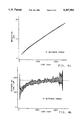
- the curves demonstrate how the stiffness for conventional thread engagement varies with load. Stiffness in the case of conventional threads only approaches constancy (linear horizontal curve) at the far right of the curve through a narrow envelope of substantial load. Also noted in the curves of FIG.
- preload force Ideally, one would like to see no slope or minimally sloping stiffness curve between a wide range of preload forces so that installation or reinstallation of a sensor would not need to be closely monitored as far as preload force is concerned. Precise monitoring and/or inspection of preload force is generally quite expensive and cumbersome.
- the curve in FIG. 2c is derived from data obtained during an accelerated creep simulation test, the vertical axis indicating thread deflection and the horizontal axis indicating load.
- a cylindrical body having an annular wall of reduced thickness (approximately 50% that used in the hysteresis and stiffness tests of FIGS. 2a and 2b) was used in the accelerated creep testing.
- Identical thread forms were used (60° standard V-thread)
- the curve exhibits rapid deformation of the threaded interface within the first decade of load cycles and suggests that conventional threads in conjunction with a full thickness annular wall may exhibit similar deformation over a sensor's lifetime.
- FIG. 3 a cross sectional illustration of a threaded portion of an annular type sensor shows a preferred thread form according to the invention.
- the circled portion of FIG. 1c referenced as numeral 3 indicates the general area for application of the preferred thread form shown in FIG. 3.
- FIG. 3 is also consistent with the thread form tested in comparison to the conventional threads previously described.
- the thread arrangement is generically referred to as a buttress thread and has a load flank substantially normal to the direction of the preload and compressive forces and a relief flank triangulated therefrom at a relatively wide angle.
- Buttress thread (ANSI B1.9) is one exemplary type of buttress thread suited for application hereto and has a load flank angle of 7° and a relief angle of 45°.
- flank angle geometries are fully within the contemplated scope of the present invention, ANSI B1.9 being mentioned herein as exemplary and not limiting.
- a preferred thread geometry, and the one illustrated in FIG. 3 and tested in comparison to the 60° standard V-thread has a load flank angle of 5° and a relief angle of approximately 56°, both angles being measured relative to a line perpendicular to the threaded member's major axis.
- a portion of the sensor body wall is illustrated as 102.
- the load bearing flank has a much greater angle offsetting it from a normal position relative the sensor axis and any force introduced on that load bearing flank would introduce radial compression of the sensor, and deformation of the sensor threads and body sufficient to cause undesirable hysteretic, gain and creep behavior heretofore explained and illustrated with reference to FIGS. 2a-2c.
- the buttress type thread is machined with the load bearing flank not quite normal to the direction of the force.
- the load bearing flank is substantially normal to the load so as to greatly limit undesirable slip and non-slip behaviors.
- Aluminum alloys are commonly used for cylinder heads because of mass and corrosion advantages over cast iron, but stiffness, creep and fatigue properties are somewhat poorer with respect thereto. For similar mass and corrosion advantages, aluminum alloys are an advantageous choice for the sensor body. Also, an aluminum alloy for the sensor body is preferred where the cylinder head to which it is matched is an aluminum alloy because of similar thermal expansion properties. Such matching of thermal expansion properties will reduce the effects that an expansion differential has upon sensor preload thereby allowing use of lower preloads and component stresses. Both improved durability and preload maintenance are expected. Without such a buttress thread for an aluminum alloy cylinder head and mating sensor body, conventional threads thereon will tend to introduce undesirable deformation upon the sensor body more so than they would if they were on a material with greater modulus of elasticity and yield strength.
- the import of the present invention is heightened in view of modern combustion engines which commonly employ aluminum alloy heads. It is likewise desirable to prevent galling of the threads which is quite likely with raw aluminum components. This can be accomplished by anodic deposition of a file-hard coating or alternatively by establishing a nickel coating such as by electrolysis over the threads of the sensor.
- FIGS. 4a through 4c show improvements to the types of behavior encountered with conventional threads and can be compared directly to corresponding FIGS. 2a through 2c .
- the curves represent laboratory measurements obtained from quasi-static axial loading tests on a material test machine.
- the material tested and methods of testing correspond substantially identically to those which generated the data used in FIGS. 2a through 2c ; the only difference being in the thread form used for the test.
- the aluminum alloy body sports a buttress thread as heretofore described and illustrated in FIG. 3 having a load flank angle of substantially 5° and a relief angle of substantially 56°.
- FIG. 4a shows improvements to the types of behavior encountered with conventional threads and can be compared directly to corresponding FIGS. 2a through 2c .
- the curves represent laboratory measurements obtained from quasi-static axial loading tests on a material test machine.
- the material tested and methods of testing correspond substantially identically to those which generated the data used in FIGS. 2a through 2c ; the only difference being in the thread form used for the
- the curve in FIG. 4b illustrative of the stiffness of the buttress thread arrangement and derived from the data used to generate the curves in FIG. 4a, shows improved stiffness characteristics over that shown in FIG. 2b .
- the range of preload forces corresponding to relatively constant stiffness is not only significantly wider, but also extends through lower preload forces. Also noted here is the lack of load-unload dependency shown in FIG. 2b as caused by the hysteretic performance of conventional threads.
- the broadened range of preload force through which stiffness is constant allows for a much larger tolerance in installation preload about a lesser nominal magnitude of preload, thereby eliminating precise preload force monitoring during original installation or reinstallation after service.
- the curve in FIG. 4c is, similar to that in FIG. 2c derived from data obtained during an accelerated creep simulation test, the vertical axis indicating thread deflection and the horizontal axis indicating load.
- An annular wall of reduced thickness was used in the accelerated testing.
- the curve shows no measured creep or deformation of buttress threads or increased hysteresis.
Landscapes
- Chemical & Material Sciences (AREA)
- Engineering & Computer Science (AREA)
- Combustion & Propulsion (AREA)
- Physics & Mathematics (AREA)
- General Physics & Mathematics (AREA)
- Measuring Fluid Pressure (AREA)
Abstract
Description
Claims (8)
Priority Applications (4)
| Application Number | Priority Date | Filing Date | Title |
|---|---|---|---|
| US08/035,139 US5367904A (en) | 1993-03-19 | 1993-03-19 | Non-intrusive cylinder pressure sensor having improved response characteristics |
| CA002115621A CA2115621C (en) | 1993-03-19 | 1994-02-14 | Non-intrusive cylinder pressure sensor having improved response characteristics |
| DE69406699T DE69406699T2 (en) | 1993-03-19 | 1994-02-24 | Engine cylinder pressure converter |
| EP94200462A EP0616203B1 (en) | 1993-03-19 | 1994-02-24 | A cylinder pressure sensor for an engine |
Applications Claiming Priority (1)
| Application Number | Priority Date | Filing Date | Title |
|---|---|---|---|
| US08/035,139 US5367904A (en) | 1993-03-19 | 1993-03-19 | Non-intrusive cylinder pressure sensor having improved response characteristics |
Publications (1)
| Publication Number | Publication Date |
|---|---|
| US5367904A true US5367904A (en) | 1994-11-29 |
Family
ID=21880895
Family Applications (1)
| Application Number | Title | Priority Date | Filing Date |
|---|---|---|---|
| US08/035,139 Expired - Lifetime US5367904A (en) | 1993-03-19 | 1993-03-19 | Non-intrusive cylinder pressure sensor having improved response characteristics |
Country Status (4)
| Country | Link |
|---|---|
| US (1) | US5367904A (en) |
| EP (1) | EP0616203B1 (en) |
| CA (1) | CA2115621C (en) |
| DE (1) | DE69406699T2 (en) |
Cited By (22)
| Publication number | Priority date | Publication date | Assignee | Title |
|---|---|---|---|---|
| US6106327A (en) * | 1998-08-17 | 2000-08-22 | General Motors Corporation | Sensor connection assembly |
| US7117726B1 (en) | 2005-06-17 | 2006-10-10 | Gm Global Technology Operations, Inc. | Method and apparatus for indirect measurement of engine cylinder pressure |
| US20110226047A1 (en) * | 2010-03-16 | 2011-09-22 | Eaton Corporation | Magnetically coded pressure detection apparatus |
| US8863569B2 (en) | 2010-03-16 | 2014-10-21 | Eaton Corporation | Magnetically coded temperature and pressure detection apparatus |
| US8915225B2 (en) | 2010-03-19 | 2014-12-23 | Eaton Corporation | Rocker arm assembly and components therefor |
| US9016252B2 (en) | 2008-07-22 | 2015-04-28 | Eaton Corporation | System to diagnose variable valve actuation malfunctions by monitoring fluid pressure in a hydraulic lash adjuster gallery |
| US9038586B2 (en) | 2010-03-19 | 2015-05-26 | Eaton Corporation | Rocker assembly having improved durability |
| US9194261B2 (en) | 2011-03-18 | 2015-11-24 | Eaton Corporation | Custom VVA rocker arms for left hand and right hand orientations |
| US9228454B2 (en) | 2010-03-19 | 2016-01-05 | Eaton Coporation | Systems, methods and devices for rocker arm position sensing |
| US9267396B2 (en) | 2010-03-19 | 2016-02-23 | Eaton Corporation | Rocker arm assembly and components therefor |
| USD750670S1 (en) | 2013-02-22 | 2016-03-01 | Eaton Corporation | Rocker arm |
| US9284859B2 (en) | 2010-03-19 | 2016-03-15 | Eaton Corporation | Systems, methods, and devices for valve stem position sensing |
| US9291075B2 (en) | 2008-07-22 | 2016-03-22 | Eaton Corporation | System to diagnose variable valve actuation malfunctions by monitoring fluid pressure in a control gallery |
| US9581058B2 (en) | 2010-08-13 | 2017-02-28 | Eaton Corporation | Development of a switching roller finger follower for cylinder deactivation in internal combustion engines |
| US9822673B2 (en) | 2010-03-19 | 2017-11-21 | Eaton Corporation | Latch interface for a valve actuating device |
| US9869211B2 (en) | 2014-03-03 | 2018-01-16 | Eaton Corporation | Valve actuating device and method of making same |
| US9874122B2 (en) | 2010-03-19 | 2018-01-23 | Eaton Corporation | Rocker assembly having improved durability |
| US9938865B2 (en) | 2008-07-22 | 2018-04-10 | Eaton Corporation | Development of a switching roller finger follower for cylinder deactivation in internal combustion engines |
| US10087790B2 (en) | 2009-07-22 | 2018-10-02 | Eaton Corporation | Cylinder head arrangement for variable valve actuation rocker arm assemblies |
| US10415439B2 (en) | 2008-07-22 | 2019-09-17 | Eaton Intelligent Power Limited | Development of a switching roller finger follower for cylinder deactivation in internal combustion engines |
| US11181013B2 (en) | 2009-07-22 | 2021-11-23 | Eaton Intelligent Power Limited | Cylinder head arrangement for variable valve actuation rocker arm assemblies |
| US11788439B2 (en) | 2010-03-19 | 2023-10-17 | Eaton Intelligent Power Limited | Development of a switching roller finger follower for cylinder deactivation in internal combustion engines |
Citations (9)
| Publication number | Priority date | Publication date | Assignee | Title |
|---|---|---|---|---|
| US3707107A (en) * | 1970-01-26 | 1972-12-26 | Hans Bieri | Screw connection for high loading |
| US4294559A (en) * | 1979-08-27 | 1981-10-13 | Pda Engineering | Pre-stressed structural joint |
| US4599021A (en) * | 1983-03-16 | 1986-07-08 | Kloster Kenneth D | Retaining nut for MacPherson strut suspension assembly |
| US4601196A (en) * | 1984-08-15 | 1986-07-22 | General Motors Corporation | Engine combustion chamber pressure sensor |
| US4602506A (en) * | 1984-06-29 | 1986-07-29 | Nissan Motor Co., Ltd. | Combustion pressure sensor arrangement |
| US4969352A (en) * | 1989-08-21 | 1990-11-13 | General Motors Corporation | Combustion pressure sensor |
| US5101659A (en) * | 1990-04-12 | 1992-04-07 | Nissan Motor Co., Ltd. | Mounting device for pressure sensor |
| US5127784A (en) * | 1989-04-19 | 1992-07-07 | Halliburton Company | Fatigue-resistant buttress thread |
| US5142914A (en) * | 1989-11-02 | 1992-09-01 | Matsushita Electric Industrial Co., Ltd. | Piezoelectric pressure sensor |
Family Cites Families (3)
| Publication number | Priority date | Publication date | Assignee | Title |
|---|---|---|---|---|
| CH372171A (en) * | 1959-06-12 | 1963-09-30 | Schweizerische Lokomotiv | Arrangement of a piezoelectric pressure sensor on a hollow body |
| JPS58118362A (en) * | 1981-12-30 | 1983-07-14 | Seibu Denki Kogyo Kk | Precision dynamic pressure nut and method for processing it |
| ATE24764T1 (en) * | 1982-04-06 | 1987-01-15 | Kistler Instrumente Ag | HIGH PRESSURE TRANSDUCER. |
-
1993
- 1993-03-19 US US08/035,139 patent/US5367904A/en not_active Expired - Lifetime
-
1994
- 1994-02-14 CA CA002115621A patent/CA2115621C/en not_active Expired - Lifetime
- 1994-02-24 DE DE69406699T patent/DE69406699T2/en not_active Expired - Lifetime
- 1994-02-24 EP EP94200462A patent/EP0616203B1/en not_active Expired - Lifetime
Patent Citations (9)
| Publication number | Priority date | Publication date | Assignee | Title |
|---|---|---|---|---|
| US3707107A (en) * | 1970-01-26 | 1972-12-26 | Hans Bieri | Screw connection for high loading |
| US4294559A (en) * | 1979-08-27 | 1981-10-13 | Pda Engineering | Pre-stressed structural joint |
| US4599021A (en) * | 1983-03-16 | 1986-07-08 | Kloster Kenneth D | Retaining nut for MacPherson strut suspension assembly |
| US4602506A (en) * | 1984-06-29 | 1986-07-29 | Nissan Motor Co., Ltd. | Combustion pressure sensor arrangement |
| US4601196A (en) * | 1984-08-15 | 1986-07-22 | General Motors Corporation | Engine combustion chamber pressure sensor |
| US5127784A (en) * | 1989-04-19 | 1992-07-07 | Halliburton Company | Fatigue-resistant buttress thread |
| US4969352A (en) * | 1989-08-21 | 1990-11-13 | General Motors Corporation | Combustion pressure sensor |
| US5142914A (en) * | 1989-11-02 | 1992-09-01 | Matsushita Electric Industrial Co., Ltd. | Piezoelectric pressure sensor |
| US5101659A (en) * | 1990-04-12 | 1992-04-07 | Nissan Motor Co., Ltd. | Mounting device for pressure sensor |
Cited By (41)
| Publication number | Priority date | Publication date | Assignee | Title |
|---|---|---|---|---|
| US6106327A (en) * | 1998-08-17 | 2000-08-22 | General Motors Corporation | Sensor connection assembly |
| US7117726B1 (en) | 2005-06-17 | 2006-10-10 | Gm Global Technology Operations, Inc. | Method and apparatus for indirect measurement of engine cylinder pressure |
| US9964005B2 (en) | 2008-07-22 | 2018-05-08 | Eaton Corporation | Method for diagnosing variable valve actuation malfunctions by monitoring fluid pressure in a control gallery |
| US10415439B2 (en) | 2008-07-22 | 2019-09-17 | Eaton Intelligent Power Limited | Development of a switching roller finger follower for cylinder deactivation in internal combustion engines |
| US9016252B2 (en) | 2008-07-22 | 2015-04-28 | Eaton Corporation | System to diagnose variable valve actuation malfunctions by monitoring fluid pressure in a hydraulic lash adjuster gallery |
| US9291075B2 (en) | 2008-07-22 | 2016-03-22 | Eaton Corporation | System to diagnose variable valve actuation malfunctions by monitoring fluid pressure in a control gallery |
| US9938865B2 (en) | 2008-07-22 | 2018-04-10 | Eaton Corporation | Development of a switching roller finger follower for cylinder deactivation in internal combustion engines |
| US9644503B2 (en) | 2008-07-22 | 2017-05-09 | Eaton Corporation | System to diagnose variable valve actuation malfunctions by monitoring fluid pressure in a hydraulic lash adjuster gallery |
| US11181013B2 (en) | 2009-07-22 | 2021-11-23 | Eaton Intelligent Power Limited | Cylinder head arrangement for variable valve actuation rocker arm assemblies |
| US10087790B2 (en) | 2009-07-22 | 2018-10-02 | Eaton Corporation | Cylinder head arrangement for variable valve actuation rocker arm assemblies |
| US8505365B2 (en) | 2010-03-16 | 2013-08-13 | Eaton Corporation | Magnetically coded pressure detection apparatus |
| US8863569B2 (en) | 2010-03-16 | 2014-10-21 | Eaton Corporation | Magnetically coded temperature and pressure detection apparatus |
| US20110226047A1 (en) * | 2010-03-16 | 2011-09-22 | Eaton Corporation | Magnetically coded pressure detection apparatus |
| US9228454B2 (en) | 2010-03-19 | 2016-01-05 | Eaton Coporation | Systems, methods and devices for rocker arm position sensing |
| US9915180B2 (en) | 2010-03-19 | 2018-03-13 | Eaton Corporation | Latch interface for a valve actuating device |
| US11788439B2 (en) | 2010-03-19 | 2023-10-17 | Eaton Intelligent Power Limited | Development of a switching roller finger follower for cylinder deactivation in internal combustion engines |
| US11530630B2 (en) | 2010-03-19 | 2022-12-20 | Eaton Intelligent Power Limited | Systems, methods, and devices for rocker arm position sensing |
| US8915225B2 (en) | 2010-03-19 | 2014-12-23 | Eaton Corporation | Rocker arm assembly and components therefor |
| US9702279B2 (en) | 2010-03-19 | 2017-07-11 | Eaton Corporation | Sensing and control of a variable valve actuation system |
| US9708942B2 (en) | 2010-03-19 | 2017-07-18 | Eaton Corporation | Rocker arm assembly and components therefor |
| US9726052B2 (en) | 2010-03-19 | 2017-08-08 | Eaton Corporation | Rocker arm assembly and components therefor |
| US9765657B2 (en) | 2010-03-19 | 2017-09-19 | Eaton Corporation | System, method and device for rocker arm position sensing |
| US9822673B2 (en) | 2010-03-19 | 2017-11-21 | Eaton Corporation | Latch interface for a valve actuating device |
| US11085338B2 (en) | 2010-03-19 | 2021-08-10 | Eaton Intelligent Power Limited | Systems, methods and devices for rocker arm position sensing |
| US9874122B2 (en) | 2010-03-19 | 2018-01-23 | Eaton Corporation | Rocker assembly having improved durability |
| US9885258B2 (en) | 2010-03-19 | 2018-02-06 | Eaton Corporation | Latch interface for a valve actuating device |
| US9284859B2 (en) | 2010-03-19 | 2016-03-15 | Eaton Corporation | Systems, methods, and devices for valve stem position sensing |
| US9267396B2 (en) | 2010-03-19 | 2016-02-23 | Eaton Corporation | Rocker arm assembly and components therefor |
| US10890086B2 (en) | 2010-03-19 | 2021-01-12 | Eaton Intelligent Power Limited | Latch interface for a valve actuating device |
| US10570786B2 (en) | 2010-03-19 | 2020-02-25 | Eaton Intelligent Power Limited | Rocker assembly having improved durability |
| US9038586B2 (en) | 2010-03-19 | 2015-05-26 | Eaton Corporation | Rocker assembly having improved durability |
| US10119429B2 (en) | 2010-03-19 | 2018-11-06 | Eaton Corporation | Systems, methods, and devices for valve stem position sensing |
| US10180087B2 (en) | 2010-03-19 | 2019-01-15 | Eaton Corporation | Rocker arm assembly and components therefor |
| US8985074B2 (en) | 2010-03-19 | 2015-03-24 | Eaton Corporation | Sensing and control of a variable valve actuation system |
| US9581058B2 (en) | 2010-08-13 | 2017-02-28 | Eaton Corporation | Development of a switching roller finger follower for cylinder deactivation in internal combustion engines |
| US10329970B2 (en) | 2011-03-18 | 2019-06-25 | Eaton Corporation | Custom VVA rocker arms for left hand and right hand orientations |
| US9194261B2 (en) | 2011-03-18 | 2015-11-24 | Eaton Corporation | Custom VVA rocker arms for left hand and right hand orientations |
| US9664075B2 (en) | 2011-03-18 | 2017-05-30 | Eaton Corporation | Custom VVA rocker arms for left hand and right hand orientations |
| USD750670S1 (en) | 2013-02-22 | 2016-03-01 | Eaton Corporation | Rocker arm |
| US9995183B2 (en) | 2014-03-03 | 2018-06-12 | Eaton Corporation | Valve actuating device and method of making same |
| US9869211B2 (en) | 2014-03-03 | 2018-01-16 | Eaton Corporation | Valve actuating device and method of making same |
Also Published As
| Publication number | Publication date |
|---|---|
| CA2115621A1 (en) | 1994-09-20 |
| DE69406699D1 (en) | 1997-12-18 |
| DE69406699T2 (en) | 1998-03-12 |
| EP0616203B1 (en) | 1997-11-12 |
| CA2115621C (en) | 1997-04-08 |
| EP0616203A1 (en) | 1994-09-21 |
Similar Documents
| Publication | Publication Date | Title |
|---|---|---|
| US5367904A (en) | Non-intrusive cylinder pressure sensor having improved response characteristics | |
| US4969352A (en) | Combustion pressure sensor | |
| US8429956B2 (en) | Pressure-measuring plug for a combustion engine | |
| CA2653736C (en) | Method and apparatus for indicating a load | |
| US4061035A (en) | Diaphragm arrangement for pressure transducers | |
| US5179857A (en) | Monitoring system for cyclically operating machines | |
| EP2201279B1 (en) | Valve testing | |
| JP7549578B2 (en) | MEASURING ROLL FOR DETERMINING A CHARACTERISTIC OF A STRIP-LIKE ARTICLE THAT IS GUIDED THROUGH THE MEASURING ROLL - Patent application | |
| JP2741177B2 (en) | Dry liner for internal combustion engines | |
| US20160017914A1 (en) | Method of setting bearing preload | |
| JPH04211B2 (en) | ||
| US4379405A (en) | Force transducer, particularly for ballistic pressure measuring | |
| US5668323A (en) | Method and apparatus for indicating a load | |
| US4056009A (en) | Diaphragm arrangement for pressure transducers | |
| US7111505B2 (en) | Multi-layer steel cylinder head gasket with integrated pressure sensor | |
| US6739183B1 (en) | Multiple-layer cylinder head gasket with integral pressure sensor apparatus for measuring pressures within engine cylinders | |
| US5233862A (en) | Apparatus for determining the torque exerted on a sealing ring that seals a duct gap between a housing and a shaft | |
| CN100573154C (en) | Magnetic fluid acceleration transducer | |
| JP5184052B2 (en) | Combustion pressure sensor | |
| CA2013127C (en) | Combustion pressure sensor | |
| CN115438432A (en) | Calculation method for bearing assembling pre-tightening amount | |
| CN109989991B (en) | Multi-rib multi-induction bolt gasket | |
| EP3707398B1 (en) | System and method for on-engine component defect detection | |
| RU2293294C2 (en) | Elastic member of device for measurement of radial pressure | |
| Booker | Discussion on Session II| |
Legal Events
| Date | Code | Title | Description |
|---|---|---|---|
| AS | Assignment |
Owner name: GENERAL MOTORS CORPORATION, MICHIGAN Free format text: ASSIGNMENT OF ASSIGNORS INTEREST.;ASSIGNOR:SELLNAU, MARK C.;REEL/FRAME:006482/0752 Effective date: 19930311 |
|
| STPP | Information on status: patent application and granting procedure in general |
Free format text: APPLICATION UNDERGOING PREEXAM PROCESSING |
|
| FPAY | Fee payment |
Year of fee payment: 4 |
|
| FPAY | Fee payment |
Year of fee payment: 8 |
|
| FPAY | Fee payment |
Year of fee payment: 12 |
|
| AS | Assignment |
Owner name: GM GLOBAL TECHNOLOGY OPERATIONS, INC., MICHIGAN Free format text: ASSIGNMENT OF ASSIGNORS INTEREST;ASSIGNOR:GENERAL MOTORS CORPORATION;REEL/FRAME:022117/0047 Effective date: 20050119 Owner name: GM GLOBAL TECHNOLOGY OPERATIONS, INC.,MICHIGAN Free format text: ASSIGNMENT OF ASSIGNORS INTEREST;ASSIGNOR:GENERAL MOTORS CORPORATION;REEL/FRAME:022117/0047 Effective date: 20050119 |
|
| AS | Assignment |
Owner name: UNITED STATES DEPARTMENT OF THE TREASURY, DISTRICT Free format text: SECURITY AGREEMENT;ASSIGNOR:GM GLOBAL TECHNOLOGY OPERATIONS, INC.;REEL/FRAME:022201/0501 Effective date: 20081231 |
|
| AS | Assignment |
Owner name: CITICORP USA, INC. AS AGENT FOR BANK PRIORITY SECU Free format text: SECURITY AGREEMENT;ASSIGNOR:GM GLOBAL TECHNOLOGY OPERATIONS, INC.;REEL/FRAME:022556/0013 Effective date: 20090409 Owner name: CITICORP USA, INC. AS AGENT FOR HEDGE PRIORITY SEC Free format text: SECURITY AGREEMENT;ASSIGNOR:GM GLOBAL TECHNOLOGY OPERATIONS, INC.;REEL/FRAME:022556/0013 Effective date: 20090409 |
|
| AS | Assignment |
Owner name: GM GLOBAL TECHNOLOGY OPERATIONS, INC., MICHIGAN Free format text: RELEASE BY SECURED PARTY;ASSIGNOR:UNITED STATES DEPARTMENT OF THE TREASURY;REEL/FRAME:023238/0015 Effective date: 20090709 |
|
| XAS | Not any more in us assignment database |
Free format text: RELEASE BY SECURED PARTY;ASSIGNOR:UNITED STATES DEPARTMENT OF THE TREASURY;REEL/FRAME:023124/0383 |
|
| AS | Assignment |
Owner name: GM GLOBAL TECHNOLOGY OPERATIONS, INC., MICHIGAN Free format text: RELEASE BY SECURED PARTY;ASSIGNORS:CITICORP USA, INC. AS AGENT FOR BANK PRIORITY SECURED PARTIES;CITICORP USA, INC. AS AGENT FOR HEDGE PRIORITY SECURED PARTIES;REEL/FRAME:023127/0326 Effective date: 20090814 |
|
| AS | Assignment |
Owner name: UNITED STATES DEPARTMENT OF THE TREASURY, DISTRICT Free format text: SECURITY AGREEMENT;ASSIGNOR:GM GLOBAL TECHNOLOGY OPERATIONS, INC.;REEL/FRAME:023155/0922 Effective date: 20090710 |
|
| AS | Assignment |
Owner name: UAW RETIREE MEDICAL BENEFITS TRUST, MICHIGAN Free format text: SECURITY AGREEMENT;ASSIGNOR:GM GLOBAL TECHNOLOGY OPERATIONS, INC.;REEL/FRAME:023161/0864 Effective date: 20090710 |
|
| AS | Assignment |
Owner name: GM GLOBAL TECHNOLOGY OPERATIONS, INC., MICHIGAN Free format text: RELEASE BY SECURED PARTY;ASSIGNOR:UAW RETIREE MEDICAL BENEFITS TRUST;REEL/FRAME:025311/0680 Effective date: 20101026 Owner name: GM GLOBAL TECHNOLOGY OPERATIONS, INC., MICHIGAN Free format text: RELEASE BY SECURED PARTY;ASSIGNOR:UNITED STATES DEPARTMENT OF THE TREASURY;REEL/FRAME:025245/0273 Effective date: 20100420 |
|
| AS | Assignment |
Owner name: WILMINGTON TRUST COMPANY, DELAWARE Free format text: SECURITY AGREEMENT;ASSIGNOR:GM GLOBAL TECHNOLOGY OPERATIONS, INC.;REEL/FRAME:025327/0222 Effective date: 20101027 |
|
| AS | Assignment |
Owner name: GM GLOBAL TECHNOLOGY OPERATIONS LLC, MICHIGAN Free format text: CHANGE OF NAME;ASSIGNOR:GM GLOBAL TECHNOLOGY OPERATIONS, INC.;REEL/FRAME:025780/0795 Effective date: 20101202 |