US536606A - Measuring liquids - Google Patents
Measuring liquids Download PDFInfo
- Publication number
- US536606A US536606A US536606DA US536606A US 536606 A US536606 A US 536606A US 536606D A US536606D A US 536606DA US 536606 A US536606 A US 536606A
- Authority
- US
- United States
- Prior art keywords
- air
- receptacle
- water
- measuring
- receptacles
- Prior art date
- Legal status (The legal status is an assumption and is not a legal conclusion. Google has not performed a legal analysis and makes no representation as to the accuracy of the status listed.)
- Expired - Lifetime
Links
- 239000007788 liquid Substances 0.000 title description 13
- XLYOFNOQVPJJNP-UHFFFAOYSA-N water Substances O XLYOFNOQVPJJNP-UHFFFAOYSA-N 0.000 description 12
- 239000012530 fluid Substances 0.000 description 2
- 238000000034 method Methods 0.000 description 2
- 239000007789 gas Substances 0.000 description 1
- 238000005259 measurement Methods 0.000 description 1
- 239000013049 sediment Substances 0.000 description 1
- 239000000126 substance Substances 0.000 description 1
Images
Classifications
-
- G—PHYSICS
- G01—MEASURING; TESTING
- G01F—MEASURING VOLUME, VOLUME FLOW, MASS FLOW OR LIQUID LEVEL; METERING BY VOLUME
- G01F15/00—Details of, or accessories for, apparatus of groups G01F1/00 - G01F13/00 insofar as such details or appliances are not adapted to particular types of such apparatus
Definitions
- Our invention relates to the measurement of fluids by the use of meters, and is designed I 5 to attain an improved method therefor, and also to provide a motor in which no valves are necessary and whose action is consequently not interfered with by the presence of sediment and foreign substances in the fluid.
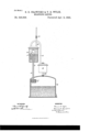
- 2 represents an inlet water pipe provided with a check-valve 3 and leading nearly to the bottom of an air-tight receptacle 4.
- siphons 5 whose longer legs lead downwardly through the cover of a larger air-tight receptacle 6, and terminate near the bottom of a small pan 7 supported in the upper part of the receptacle.
- An outlet pipe for the liquid is provided near the bottom of the lower reservoir, and the action of the device is as follows: The water entering the upper reservoir, rises in the same until it reaches the level of the bend in the siphon, when it begins to flow there- 4 5 through into the pan 7 of the lower receptacle. In passing down through the longer leg, the water draws through the pipe 8 aquantity of air exactly proportionate to the amount of the downflowing water, and the water and air entering the pan 7 pass out into the lower receptacle, whence the water flows out through the outlet, while the air passes back through the meter 11 and again enters the top of the upper receptacle.
- the flow of air through the meter is caused by the unbalanced condition induced by the flowing water which, drawing air from the upper receptacle, tends to cause a vacuum therein, while the inflowing air and water raisev the pressure in the lower receptacle.
Landscapes
- Physics & Mathematics (AREA)
- Fluid Mechanics (AREA)
- General Physics & Mathematics (AREA)
- Sampling And Sample Adjustment (AREA)
Description
(NoModeL) v -s. E. GRAWFORD- & T. B.;WYLIE.- MEASURING LIQUIDS. I N0. 536,606. Patented A r; 2,1696.
WITNESSES INVENTOR m {M s. W
' 4L, WW
no: NORRIS was so. woraunianmsummom n, c
UNITED STAT S PAT NT Osman.
A SAMUEL E. CRAWFORD, OF AVALON, AND THOMAS E. WYLIE, OF ALLEGHENY,
' PENNSYLVANIA.
MEASURING LIQUIDS.
SPECIFICATION forming part of Letters Patent No. 536,606, dated April 2, 1 895.
- Application filed JHIIBZO, 1894. Serial No- 515,0s4. (N model.)
To all whom it may concern.-
Be it known that we, SAMUEL E. CRAW- FORD, of Avalon, and THOMAS E. WYLIE, of Allegheny, in the county of Allegheny and State of Pennsylvania, have invented a new and useful Improvement in Measuring Liquids, of which the'following is a full, clear, and exact description, reference being had to the accompanying drawing, forming part of this specification, in which the figure is a side elevation, partly in section, of our improved proportional meter.
Our invention relates to the measurement of fluids by the use of meters, and is designed I 5 to attain an improved method therefor, and also to provide a motor in which no valves are necessary and whose action is consequently not interfered with by the presence of sediment and foreign substances in the fluid.
In the drawing, 2 represents an inlet water pipe provided with a check-valve 3 and leading nearly to the bottom of an air-tight receptacle 4. Within this receptacle are provided siphons 5, whose longer legs lead downwardly through the cover of a larger air-tight receptacle 6, and terminate near the bottom of a small pan 7 supported in the upper part of the receptacle. Into the longer legs of the siphons, near the bottom of the upper recep- 3o tacle and below the level of the shorter legs, lead air-pipes 8, terminating near the top of the receptacle, and from the closed tops of the two receptacles pipes 9 and 10 lead to opposite ends ofa meter 11 of the usual con- 3 5 struction for measuring air or gases. The siphons are of difierent height so that the water may pass therethrough successively as it rises in the receptacle.
An outlet pipe for the liquid is provided near the bottom of the lower reservoir, and the action of the device is as follows:The water entering the upper reservoir, rises in the same until it reaches the level of the bend in the siphon, when it begins to flow there- 4 5 through into the pan 7 of the lower receptacle. In passing down through the longer leg, the water draws through the pipe 8 aquantity of air exactly proportionate to the amount of the downflowing water, and the water and air entering the pan 7 pass out into the lower receptacle, whence the water flows out through the outlet, while the air passes back through the meter 11 and again enters the top of the upper receptacle. The flow of air through the meter is caused by the unbalanced condition induced by the flowing water which, drawing air from the upper receptacle, tends to cause a vacuum therein, while the inflowing air and water raisev the pressure in the lower receptacle. By measuring the air passing through the meter, this being a constant fraction of the water which draws in and carries it, the amount of water passing is easily obtained.
The advantages of the device are apparent, since no valves of any kind are used, and 6 there is no direct measuring of the water itself. By using an elevated pan in the second receptacle, the level above the point of exit of the connecting pipe is maintained uniform.
-Many variations in the form and arrangement of the parts may be made by the skilled mechanic without departing from our invention, since we consider ourselves the first to measure a flowing liquid indirectly by measuring the air taken in thereby.
to claim 1 1. The method of measuring floving liquids consisting in passing the same through a conduit having an air inlet, allowing the flowing 8o liquid to draw in air through said inlet, and determining the amount of air drawn in thereby, giving a constant factor of the amount of liquid; substantiallyas described.
2. The combination with two receptacles, of an inlet pipe leading to one receptacle, a connection leading therefrom to the second receptacle, an air inlet for the connection through which the flowing liquid may draw in air, and a meter connected to the second receptacle and arranged to measure the air drawn in by the liquid; substantially as described.
3. The combination with two receptacles, of an inlet pipe leading to one receptacle, a 5 connection leading therefrom to the second receptacle, an air inlet for the connection through which the following liquid may draw Y in air, and a meter connected 'to the upper parts of both receptacles; substantially as de- [06 scribed.
4. The combination with two receptacles,
6. The combination with two receptacles, I5
of an inlet pipe leading to one receptacle, a connection leading therefrom to a second receptacle, an air inlet for the connection through which the flowing liquid may draw in air, and a meter connected to one of said 20 receptacles; substantially as described.
In testimony whereof we have hereunto set our hands.
SAML. E. CRAWFORD. THOMAS E. WYLIE. Witnesses:
H. M. CORWIN, V. B. Oonwm.
Publications (1)
| Publication Number | Publication Date |
|---|---|
| US536606A true US536606A (en) | 1895-04-02 |
Family
ID=2605367
Family Applications (1)
| Application Number | Title | Priority Date | Filing Date |
|---|---|---|---|
| US536606D Expired - Lifetime US536606A (en) | Measuring liquids |
Country Status (1)
| Country | Link |
|---|---|
| US (1) | US536606A (en) |
Cited By (2)
| Publication number | Priority date | Publication date | Assignee | Title |
|---|---|---|---|---|
| US3363461A (en) * | 1965-05-26 | 1968-01-16 | Peerless Paint & Varnish Corp | Method for measuring flow |
| US3659629A (en) * | 1970-05-04 | 1972-05-02 | Ahldea Corp | Liquid flow regulator and monitor for corporeal infusion system and method of using the same |
-
0
- US US536606D patent/US536606A/en not_active Expired - Lifetime
Cited By (2)
| Publication number | Priority date | Publication date | Assignee | Title |
|---|---|---|---|---|
| US3363461A (en) * | 1965-05-26 | 1968-01-16 | Peerless Paint & Varnish Corp | Method for measuring flow |
| US3659629A (en) * | 1970-05-04 | 1972-05-02 | Ahldea Corp | Liquid flow regulator and monitor for corporeal infusion system and method of using the same |
Similar Documents
| Publication | Publication Date | Title |
|---|---|---|
| US301391A (en) | Siphon | |
| US536606A (en) | Measuring liquids | |
| US1599081A (en) | Apparatus for dispensing liquids through meters | |
| US1130792A (en) | Separator for meters. | |
| US1943039A (en) | Proportioning and feeding device | |
| US1068280A (en) | Apparatus for measuring flow of liquids in closed conduits. | |
| US1196735A (en) | Liquid-flow-measuring apparatus. | |
| US1097834A (en) | Gas-meter-testing device. | |
| US248574A (en) | Filter | |
| US224108A (en) | Measuring-faucet | |
| SU1578483A1 (en) | Gas flowmeter | |
| US406990A (en) | Combined pressure-gage and safety-valve | |
| US956374A (en) | Liquid-meter. | |
| JPH0316027Y2 (en) | ||
| US165447A (en) | Improvement in liquid | |
| US968664A (en) | Regulator for water-heating systems. | |
| US337910A (en) | Joseph b | |
| US886255A (en) | Steam-meter. | |
| US203685A (en) | Improvement in rotary water-meters | |
| US1127692A (en) | Steam-meter. | |
| US1195736A (en) | of sayville | |
| US197258A (en) | Improvement in feed-water regulators for steam-boilers | |
| US1120583A (en) | Dividing-box. | |
| US183306A (en) | Improvement in liquid-measures | |
| US835559A (en) | Apparatus for gas analysis. |