US5351002A - Test probe - Google Patents
Test probe Download PDFInfo
- Publication number
- US5351002A US5351002A US07/569,618 US56961890A US5351002A US 5351002 A US5351002 A US 5351002A US 56961890 A US56961890 A US 56961890A US 5351002 A US5351002 A US 5351002A
- Authority
- US
- United States
- Prior art keywords
- rod
- handle
- probe
- terminal
- face
- Prior art date
- Legal status (The legal status is an assumption and is not a legal conclusion. Google has not performed a legal analysis and makes no representation as to the accuracy of the status listed.)
- Expired - Fee Related
Links
Images

Classifications
-
- G—PHYSICS
- G01—MEASURING; TESTING
- G01R—MEASURING ELECTRIC VARIABLES; MEASURING MAGNETIC VARIABLES
- G01R1/00—Details of instruments or arrangements of the types included in groups G01R5/00 - G01R13/00 and G01R31/00
- G01R1/02—General constructional details
- G01R1/06—Measuring leads; Measuring probes
- G01R1/067—Measuring probes
- G01R1/06788—Hand-held or hand-manipulated probes, e.g. for oscilloscopes or for portable test instruments
Definitions
- This application deals generally with a probe for establishing a temporary electrical test connection with a terminal or wire of a circuit.
- a probe for establishing a temporary electrical test connection with a terminal or wire of a circuit.
- a probe typically includes an insulated handle, a rod extending from the handle, and a lead on the handle which is in electrical contact with the rod and adapted to be connected to a test wire.
- Electrical connection with the terminal or a connector may be accomplished by sliding the rod of the probe inside the connector until the rod is disposed against the terminal. Since the terminal is flat and the rod is cylindrical, only a minimal surface area of the rod contacts the terminal. As a result, electrical contact between the probe and the terminal is disadvantageously minimized.
- Another object of the invention is to provide a test probe adapted to provide maximum electrical contact with the terminal.
- Another object of the invention is to provide a test probe having a rod of minimal cross section so as to enable access to a terminal in a confined space.
- Another object of the invention is to provide a test probe having a test lead protected from incidental contact with neighboring components.
- Another object of the invention is to provide a probe which is inexpensive and easy to manufacture.
- an electrical test probe comprising a handle and a rod including a free end and an opposite end secured in the handle, the rod including a longitudinally extending generally flat face, the rod being adapted to be disposed against an electrical terminal to be tested such that the flat side abuts the terminal,
- the handle includes a cavity in the end opposite the end securing the rod, the end of the rod secured in the handle residing in the cavity for connection to a test lead of a meter.
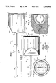
- FIG. 1 is a side-elevational view of a test probe, on an enlarged scale, embodying the features of the present invention
- FIG. 2 is a top-plan view of the test probe, with a portion of the rod therein broken away;
- FIG. 3 is a cross-sectional view of the rod, taken along the line 3--3 of FIG. 1;
- FIG. 4 is a cross-sectional view taken along the line 4--4 of FIG. 2;
- FIG. 5 is an end view taken along the line 5--5 of FIG. 1;
- FIG. 6 is a side-elevational view of the test probe in electrical connection with a terminal inside a connector, the connector being broken away and shown in partial cross-section;
- FIG. 7 is a cross-sectional view taken along the line 7--7 of FIG. 6;
- FIG. 8 is a top-plan view of a pair of probes in electrical connection with adjacent terminals inside the connector, the connector being broken away and shown in partial cross-section;
- FIG. 9 is a perspective view of the test probe connected to a test lead of a meter.
- test probe 20 constructed in accordance with the present invention.
- the probe 20 is adapted to make an electrical test connection into a connector 70 such as the automotive connector shown in FIG. 6.
- the probe 20 comprises a handle 30 and a rod 50.
- the handle 30 includes a generally cylindrical body 31 made of non-conducting material- The body 31 has opposite ends 32 and 33 and an outer surface 34.
- the outer surface 34 includes a thumb-receiving flat portion 35 adjacent the end 32 and at an acute angle with respect to the longitudinal axis of the rod 50.
- Another finger can be positioned on the portion 36 of surface 34 which is opposite the portion 35.
- the rod 50 includes a free end 51 having a chamfered tip 52.
- a generally semi-spherical cavity 37 extends from the end 33 into the body 31.
- the cavity 37 defines a circumferential lip 38 at the end 33.
- the rod 50 includes an end 53, opposite the free end 51, secured in the handle 31.
- the end 53 extends through the body 31 and terminates in a loop 54 residing in the cavity 37 for connection to a test lead 55 (FIG. 9) of a meter (not shown).
- a test lead 55 (FIG. 9) of a meter (not shown).
- FIG. 4 the segment of the rod between segment 58 and loop 54 is shown as sinuous (FIG. 4) that segment could also be straight, but flattened on its sides, for example, to provide good retention by the body 31.
- the cavity 37 extends into the body 31 a depth sufficient to receive the entire loop 54.
- the rod 50 includes a first segment 56 having a longitudinally extending flat face 57 and a second segment 58 of circular cross section extending from the first segment 56 and into the handle 30.
- the first segment 56 is substantially longer than the second segment 58.
- the rod 50 is preferably made of spring steel.
- the rod 50 is oriented and secured to the handle 30 such that the thumb-receiving portion 35 is directed oppositely to the flat face 57.
- the finger-receiving portion 36 and the flat face portion 57 of rod 50 face the same direction.
- the probe 20 is adapted to establish an electrical connection into the connector 70.
- the connector 70 includes a plurality of terminal ports 73.
- a terminal 74 and a wire 75 connected thereto are disposed in each of the ports 73.
- the wire 75 extends through a flexible rubber connector seal 76 disposed in each of the ports 73.
- the wire 75 is comprised of a metal core surrounded by an insulation layer.
- the electrical connection between the rod 50 and the terminal 74 is established as follows.
- the probe 20 is grasped by a user's hand such that the thumb is placed on the portion 35 and the index finger is placed on the portion 36.
- the user is aware of the orientation of the face 57 with respect to the wire 75 without examining the rod 50.
- the probe 20 can easily be positioned such that the face 57 abuts the wire 75.
- the probe 20 is then slid inwardly between the seal 76 and along the wire 75, with the face 57 in contact therewith, until the rod 50 is disposed against the terminal 74 (FIG. 7).
- the test lead 55 is then coupled to the loop 54 (FIG. 9) so that resistance tests or the like may be performed.
- the diameter of the handle 30 causes the displacement of the wire 75 during insertion, in turn causing the displacement the of terminal 74 towards the rod 50, to enhance the contact between the flat face 57 and the terminal 74. Further, the diameter of the handle 30 is such as to assure that the wire portion 50 of one probe does not contact the wire portion 50 of another probe 20 being used in an adjacent port 73 (FIG. 8).
- segment 56 is such as to minimize deformation, and thus damage, to the connector seal 76.
Abstract
Description
Claims (12)
Priority Applications (1)
| Application Number | Priority Date | Filing Date | Title |
|---|---|---|---|
| US07/569,618 US5351002A (en) | 1990-08-20 | 1990-08-20 | Test probe |
Applications Claiming Priority (1)
| Application Number | Priority Date | Filing Date | Title |
|---|---|---|---|
| US07/569,618 US5351002A (en) | 1990-08-20 | 1990-08-20 | Test probe |
Publications (1)
| Publication Number | Publication Date |
|---|---|
| US5351002A true US5351002A (en) | 1994-09-27 |
Family
ID=24276147
Family Applications (1)
| Application Number | Title | Priority Date | Filing Date |
|---|---|---|---|
| US07/569,618 Expired - Fee Related US5351002A (en) | 1990-08-20 | 1990-08-20 | Test probe |
Country Status (1)
| Country | Link |
|---|---|
| US (1) | US5351002A (en) |
Cited By (3)
| Publication number | Priority date | Publication date | Assignee | Title |
|---|---|---|---|---|
| US5716231A (en) * | 1996-08-29 | 1998-02-10 | Snap-On Technologies, Inc. | Sensor breakout lead |
| US5977786A (en) * | 1993-07-12 | 1999-11-02 | Mania Gmbh & Co. | Adapter including solid body |
| US20060192545A1 (en) * | 2005-02-28 | 2006-08-31 | Static Control Components, Inc. | Voltage detection pole |
Citations (26)
| Publication number | Priority date | Publication date | Assignee | Title |
|---|---|---|---|---|
| US1221524A (en) * | 1916-04-20 | 1917-04-03 | Frankel Connector Company Inc | Extension attachment for testing-clips. |
| US2212307A (en) * | 1939-01-24 | 1940-08-20 | Henry C Smida | Electric tester |
| US2457506A (en) * | 1945-09-11 | 1948-12-28 | Steffen H Sorensen | Safety prod |
| US2476115A (en) * | 1945-01-10 | 1949-07-12 | Runbaken Julian Henry | Electrical testing instrument |
| US2517032A (en) * | 1947-03-29 | 1950-08-01 | Rogers Leonard | Circuit testing device |
| US2529270A (en) * | 1949-02-26 | 1950-11-07 | Webster Robert | Self-piercing and self-holding test prod |
| GB683034A (en) * | 1950-02-24 | 1952-11-19 | Electrical & Auto Products 193 | Improvements relating to high tension testing devices |
| US2702892A (en) * | 1951-02-02 | 1955-02-22 | Youger Robert Nelson | Electrical test probe |
| US2714196A (en) * | 1953-03-16 | 1955-07-26 | George M Melehan | Self-holding tool for testing electric circuits |
| FR1132868A (en) * | 1955-04-20 | 1957-03-18 | Advanced rod for testing electrical conductors | |
| US3072876A (en) * | 1959-06-16 | 1963-01-08 | Ibm | Detachable connector |
| US3072877A (en) * | 1961-05-05 | 1963-01-08 | George O Landwehr | Connection device |
| US3182257A (en) * | 1961-05-18 | 1965-05-04 | Motorola Inc | Electronic test probe |
| US3201746A (en) * | 1963-07-31 | 1965-08-17 | Crawford S Askew | Test probe with grappler |
| US3402351A (en) * | 1965-05-20 | 1968-09-17 | Ite Circuit Breaker Ltd | Phase and voltage detector |
| US3644877A (en) * | 1970-07-10 | 1972-02-22 | Carbonneau Ind Inc | Test clip for electrical conductor |
| US3757218A (en) * | 1971-12-13 | 1973-09-04 | Keithley Instruments | Electrical testing instrument structure |
| US3821689A (en) * | 1972-09-29 | 1974-06-28 | Raytheon Co | Electrical connector |
| US3992073A (en) * | 1975-11-24 | 1976-11-16 | Technical Wire Products, Inc. | Multi-conductor probe |
| US4004843A (en) * | 1975-09-25 | 1977-01-25 | Westinghouse Electric Corporation | Probe pin |
| US4178058A (en) * | 1978-06-08 | 1979-12-11 | Swenson John H | Test probe for telephone wire connector |
| US4214132A (en) * | 1978-01-24 | 1980-07-22 | Kelso Thomas W | Testing tools for modular telephone system |
| DE3005255A1 (en) * | 1980-02-13 | 1981-08-20 | Rausch & Pausch, 8672 Selb | HV tester for electrical connector components - has two rod-shaped electrodes inter connected by flexible cable |
| US4716365A (en) * | 1985-10-11 | 1987-12-29 | Lisle Corporation | Circuit tester |
| US4721903A (en) * | 1985-02-27 | 1988-01-26 | The Boeing Company | Probe and method for electrically contacting surfaces with protective coatings |
| US4829255A (en) * | 1987-05-22 | 1989-05-09 | Amp Incorporated | Probe for sealed connector |
-
1990
- 1990-08-20 US US07/569,618 patent/US5351002A/en not_active Expired - Fee Related
Patent Citations (26)
| Publication number | Priority date | Publication date | Assignee | Title |
|---|---|---|---|---|
| US1221524A (en) * | 1916-04-20 | 1917-04-03 | Frankel Connector Company Inc | Extension attachment for testing-clips. |
| US2212307A (en) * | 1939-01-24 | 1940-08-20 | Henry C Smida | Electric tester |
| US2476115A (en) * | 1945-01-10 | 1949-07-12 | Runbaken Julian Henry | Electrical testing instrument |
| US2457506A (en) * | 1945-09-11 | 1948-12-28 | Steffen H Sorensen | Safety prod |
| US2517032A (en) * | 1947-03-29 | 1950-08-01 | Rogers Leonard | Circuit testing device |
| US2529270A (en) * | 1949-02-26 | 1950-11-07 | Webster Robert | Self-piercing and self-holding test prod |
| GB683034A (en) * | 1950-02-24 | 1952-11-19 | Electrical & Auto Products 193 | Improvements relating to high tension testing devices |
| US2702892A (en) * | 1951-02-02 | 1955-02-22 | Youger Robert Nelson | Electrical test probe |
| US2714196A (en) * | 1953-03-16 | 1955-07-26 | George M Melehan | Self-holding tool for testing electric circuits |
| FR1132868A (en) * | 1955-04-20 | 1957-03-18 | Advanced rod for testing electrical conductors | |
| US3072876A (en) * | 1959-06-16 | 1963-01-08 | Ibm | Detachable connector |
| US3072877A (en) * | 1961-05-05 | 1963-01-08 | George O Landwehr | Connection device |
| US3182257A (en) * | 1961-05-18 | 1965-05-04 | Motorola Inc | Electronic test probe |
| US3201746A (en) * | 1963-07-31 | 1965-08-17 | Crawford S Askew | Test probe with grappler |
| US3402351A (en) * | 1965-05-20 | 1968-09-17 | Ite Circuit Breaker Ltd | Phase and voltage detector |
| US3644877A (en) * | 1970-07-10 | 1972-02-22 | Carbonneau Ind Inc | Test clip for electrical conductor |
| US3757218A (en) * | 1971-12-13 | 1973-09-04 | Keithley Instruments | Electrical testing instrument structure |
| US3821689A (en) * | 1972-09-29 | 1974-06-28 | Raytheon Co | Electrical connector |
| US4004843A (en) * | 1975-09-25 | 1977-01-25 | Westinghouse Electric Corporation | Probe pin |
| US3992073A (en) * | 1975-11-24 | 1976-11-16 | Technical Wire Products, Inc. | Multi-conductor probe |
| US4214132A (en) * | 1978-01-24 | 1980-07-22 | Kelso Thomas W | Testing tools for modular telephone system |
| US4178058A (en) * | 1978-06-08 | 1979-12-11 | Swenson John H | Test probe for telephone wire connector |
| DE3005255A1 (en) * | 1980-02-13 | 1981-08-20 | Rausch & Pausch, 8672 Selb | HV tester for electrical connector components - has two rod-shaped electrodes inter connected by flexible cable |
| US4721903A (en) * | 1985-02-27 | 1988-01-26 | The Boeing Company | Probe and method for electrically contacting surfaces with protective coatings |
| US4716365A (en) * | 1985-10-11 | 1987-12-29 | Lisle Corporation | Circuit tester |
| US4829255A (en) * | 1987-05-22 | 1989-05-09 | Amp Incorporated | Probe for sealed connector |
Non-Patent Citations (2)
| Title |
|---|
| Cover page and p. 358 from Snap On Tools Corp. s 1990 catalog entitled Snap On . * |
| Cover page and p. 358 from Snap-On Tools Corp.'s 1990 catalog entitled "Snap-On". |
Cited By (3)
| Publication number | Priority date | Publication date | Assignee | Title |
|---|---|---|---|---|
| US5977786A (en) * | 1993-07-12 | 1999-11-02 | Mania Gmbh & Co. | Adapter including solid body |
| US5716231A (en) * | 1996-08-29 | 1998-02-10 | Snap-On Technologies, Inc. | Sensor breakout lead |
| US20060192545A1 (en) * | 2005-02-28 | 2006-08-31 | Static Control Components, Inc. | Voltage detection pole |
Similar Documents
| Publication | Publication Date | Title |
|---|---|---|
| US4057313A (en) | Test clip | |
| US7456642B2 (en) | Handheld electronic test probe assembly | |
| US3506949A (en) | Electrical connector clip device | |
| JPS6341497B2 (en) | ||
| US2438350A (en) | Test probe | |
| US5351002A (en) | Test probe | |
| CN208350862U (en) | Scalable conducting probe | |
| CN213023251U (en) | Spring probe for testing integrated circuit | |
| US2485881A (en) | Test prod | |
| US5184065A (en) | Twist lock probe tip | |
| US5717328A (en) | Method and apparatus for using a miniature probe as a hand held probe | |
| US8368415B2 (en) | Multi-position probe circuit tester | |
| US4005362A (en) | Electrical circuit continuity tester | |
| US2580682A (en) | Electrical test prod | |
| US2778992A (en) | Electrical circuit device | |
| US2925578A (en) | Probe circuit closer | |
| US2851672A (en) | Insulated spring clip | |
| US2916699A (en) | Combination probe and continuity tester | |
| US3515989A (en) | Magnetic electrical test probes | |
| US6998859B1 (en) | Test probe with side arm | |
| CN212459758U (en) | Elastic crimping device | |
| US3348190A (en) | Test clip | |
| JPH04216470A (en) | Probe | |
| CN208013260U (en) | Automobile circuit tests Integrated Probe | |
| JPH0411176Y2 (en) |
Legal Events
| Date | Code | Title | Description |
|---|---|---|---|
| AS | Assignment |
Owner name: SNAP-ON TOOLS CORPORATION, KENOSHA, WI A CORP. OF Free format text: ASSIGNMENT OF ASSIGNORS INTEREST.;ASSIGNORS:WOLLERT, GARY S.;ALHO, TIMOTHY J.;BRAUN, ROBERT D.;REEL/FRAME:005410/0681 Effective date: 19900809 |
|
| AS | Assignment |
Owner name: SNAP-ON INCORPORATED, WISCONSIN Free format text: ASSIGNMENT OF ASSIGNORS INTEREST;ASSIGNOR:SNAP-ON TOOLS CORPORATION;REEL/FRAME:007013/0511 Effective date: 19940422 |
|
| AS | Assignment |
Owner name: SNAP-ON INCORPORATED, WISCONSIN Free format text: CERTIFICATE OF AMENDMENT OF SNAP-ON TOOLS CORPORATION CHANGING ITS NAME EFFECTIVE 4-22-94;ASSIGNOR:SNAP-ON TOOLS CORPORATION;REEL/FRAME:007113/0747 Effective date: 19940422 |
|
| CC | Certificate of correction | ||
| AS | Assignment |
Owner name: SNAP-ON TECHNOLOGIES, INC., ILLINOIS Free format text: ASSIGNMENT OF ASSIGNORS INTEREST;ASSIGNOR:SNAP-ON TOOLS WORLDWIDE, INC.;REEL/FRAME:007881/0588 Effective date: 19951229 Owner name: SNAP-ON TOOLS WORLDWIDE, INC., ILLINOIS Free format text: ASSIGNMENT OF ASSIGNORS INTEREST;ASSIGNOR:SNAP-ON INCORPORATED;REEL/FRAME:007881/0532 Effective date: 19951229 |
|
| FPAY | Fee payment |
Year of fee payment: 4 |
|
| FEPP | Fee payment procedure |
Free format text: PAYOR NUMBER ASSIGNED (ORIGINAL EVENT CODE: ASPN); ENTITY STATUS OF PATENT OWNER: LARGE ENTITY |
|
| FPAY | Fee payment |
Year of fee payment: 8 |
|
| REMI | Maintenance fee reminder mailed | ||
| AS | Assignment |
Owner name: SNAP-ON INCORPORATED, WISCONSIN Free format text: MERGER;ASSIGNOR:SNAP-ON TECHNOLOGIES, INC.;REEL/FRAME:015209/0414 Effective date: 20031219 |
|
| REMI | Maintenance fee reminder mailed | ||
| LAPS | Lapse for failure to pay maintenance fees | ||
| STCH | Information on status: patent discontinuation |
Free format text: PATENT EXPIRED DUE TO NONPAYMENT OF MAINTENANCE FEES UNDER 37 CFR 1.362 |
|
| FP | Lapsed due to failure to pay maintenance fee |
Effective date: 20060927 |