US5341694A - Diamond anvil having diamonds with curved edges - Google Patents
Diamond anvil having diamonds with curved edges Download PDFInfo
- Publication number
- US5341694A US5341694A US07/849,867 US84986792A US5341694A US 5341694 A US5341694 A US 5341694A US 84986792 A US84986792 A US 84986792A US 5341694 A US5341694 A US 5341694A
- Authority
- US
- United States
- Prior art keywords
- diamond
- diamonds
- bearing
- bearing surface
- continuous curved
- Prior art date
- Legal status (The legal status is an assumption and is not a legal conclusion. Google has not performed a legal analysis and makes no representation as to the accuracy of the status listed.)
- Expired - Fee Related
Links
Images


Classifications
-
- G—PHYSICS
- G01—MEASURING; TESTING
- G01N—INVESTIGATING OR ANALYSING MATERIALS BY DETERMINING THEIR CHEMICAL OR PHYSICAL PROPERTIES
- G01N3/00—Investigating strength properties of solid materials by application of mechanical stress
- G01N3/02—Details
- G01N3/04—Chucks
-
- G—PHYSICS
- G01—MEASURING; TESTING
- G01N—INVESTIGATING OR ANALYSING MATERIALS BY DETERMINING THEIR CHEMICAL OR PHYSICAL PROPERTIES
- G01N21/00—Investigating or analysing materials by the use of optical means, i.e. using sub-millimetre waves, infrared, visible or ultraviolet light
- G01N21/01—Arrangements or apparatus for facilitating the optical investigation
- G01N21/03—Cuvette constructions
- G01N21/0317—High pressure cuvettes
-
- G—PHYSICS
- G01—MEASURING; TESTING
- G01N—INVESTIGATING OR ANALYSING MATERIALS BY DETERMINING THEIR CHEMICAL OR PHYSICAL PROPERTIES
- G01N2203/00—Investigating strength properties of solid materials by application of mechanical stress
- G01N2203/02—Details not specific for a particular testing method
- G01N2203/04—Chucks, fixtures, jaws, holders or anvils
- G01N2203/0482—Chucks, fixtures, jaws, holders or anvils comprising sensing means
- G01N2203/0488—Diamond anvil cells
Definitions
- the present invention relates to the structure of diamonds which are used in a so-called “diamond anvil”.
- a diamond anvil is an apparatus which allows direct viewing or monitoring of a material that is highly compressed between two surfaces. Scientific American, Vol. 250 (April, 1984) pp. 54-62.
- Diamond anvil apparatus includes a pair of circularly shaped diamonds coaxially arranged with facing, plane parallel bearing surfaces and a device for applying a force to these diamonds tending to press the bearing surfaces together. Pressures higher than those at the center of the earth have been achieved with this apparatus.
- the diamond anvil has been developed from the so-called "Bridgeman anvil", circa 1905, which used tungsten carbide for one or both of the pressure producing surfaces and was opaque to visible wavelength radiation.
- Diamond anvil apparatus has employed circularly shaped, brilliant cut diamonds arranged coaxially with their top or bottom facets facing each other and serving as the bearing surfaces that apply a force to the test material. This force tending to press the bearing surfaces together which may be generated by a hydraulic press or a screw device, etc., is applied in the axial direction to the opposite facing surfaces of the two diamonds.
- a malleable gasket is arranged between the two diamonds.
- This gasket has a central opening for the test material and comes in contact with the edges of the bearing surfaces on opposite sides. When the bearing surfaces of the two diamonds are pressed toward each other, the gasket is compressed permitting the diamonds to approach each other and apply a force to the test material.
- peripheral surfaces have a constant radius of curvature or any similar curvature which maximally resists fracture.
- FIG. 1 is an elevational view, partly in cross section, showing the principal components of diamond anvil apparatus as it is known in the prior art.
- FIG. 2 is an enlarged, detailed elevational view of the bearing surface of a diamond employed in the diamond anvil apparatus of FIG. 1.
- FIG. 3 is an enlarged, detailed elevational view of the bearing surface of a diamond for use in the diamond anvil apparatus of FIG. 1, according to a preferred embodiment of the present invention.
- FIG. 4 is a plan view of the diamond bearing surface of FIG. 3.
- FIGS. 5A and 5B are cross-sectional views of one edge of the diamond bearing surface of FIG. 3 showing the curvature in detail.
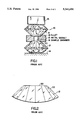
- FIG. 6 is a plan view the bearing surface of a diamond with fewer facets than the diamond of FIGS. 3 and 4, such bearing surface having a curved peripheral surface according to the present invention.
- FIG. 7 is a perspective view of the diamond bearing surface of FIG. 6.
- FIG. 1 illustrates typical diamond anvil apparatus as it is known in the art.
- the apparatus 10 comprises a circularly shaped upper diamond 11, a circularly shaped lower diamond 12, and a metal gasket 13 arranged coaxially between a base 14 and a hydraulic press 15 for applying a compressive force to the two diamonds and the metal gasket.
- the metal gasket is provided with a sample chamber 16 for the material to be tested between the facing, plane parallel bearing surfaces 18 and 20 of the upper diamond and lower diamond, respectively.
- the bearing surface 20 has a sharp edge at its periphery which merges into the tapered facets 22 of the diamond. This sharp edge is subject to fracture when urged, with great compressive force, against the facing diamond.
- FIGS. 3 and 4 illustrate the improvement according the present invention wherein the sharp edges at the periphery of the bearing surface are replaced by a curved peripheral surface that blends into the planar bearing surface and eliminates the fragile area.
- the curved surface 21 may have a constant radius R which originates from a point on a line 23 extending axially through the diamond and terminating at the edge of the bearing surface 20.
- the radius of curvature may change continuously from a value R on line 23 to a greater or lesser value to form a parabola or some other smooth curve.
- the curved surface 21 is made tangent to the bearing surface 20 at the periphery thereof; i.e, where the line 23 (or, more correctly, the cylinder) intersects.
- the curved surface 21 can be formed by any known method or means.
- these surfaces may be formed by the well-known technique of producing hemispherical surfaces on diamond phonograph needles.
- FIGS. 6 and 7 illustrate the application of the invention to a diamond having eight facets around its periphery. Provision of a continuous curved surface 27 at the periphery of the bearing surface 26 in a diamond 25 eliminates the sharp edges which would otherwise be present.
Landscapes
- Physics & Mathematics (AREA)
- Health & Medical Sciences (AREA)
- Life Sciences & Earth Sciences (AREA)
- Chemical & Material Sciences (AREA)
- Analytical Chemistry (AREA)
- Biochemistry (AREA)
- General Health & Medical Sciences (AREA)
- General Physics & Mathematics (AREA)
- Immunology (AREA)
- Pathology (AREA)
- Crystals, And After-Treatments Of Crystals (AREA)
Abstract
A diamond anvil of the type comprising (a) a pair of diamonds having a facing, plane parallel bearing surfaces and (b) a device for applying a force to the diamonds tending to press the bearing surfaces together. Both diamonds have a peripheral surface, extending outward from the bearing surface, which is tangent to the bearing surface at the interface thereto and which tapers away from the bearing surface with a continuous curved surface.
Description
The present invention relates to the structure of diamonds which are used in a so-called "diamond anvil".
A diamond anvil is an apparatus which allows direct viewing or monitoring of a material that is highly compressed between two surfaces. Scientific American, Vol. 250 (April, 1984) pp. 54-62. Diamond anvil apparatus includes a pair of circularly shaped diamonds coaxially arranged with facing, plane parallel bearing surfaces and a device for applying a force to these diamonds tending to press the bearing surfaces together. Pressures higher than those at the center of the earth have been achieved with this apparatus.
The diamond anvil has been developed from the so-called "Bridgeman anvil", circa 1905, which used tungsten carbide for one or both of the pressure producing surfaces and was opaque to visible wavelength radiation. In 1959, Weir, Lippincott, Van Valkenberg and Bunting, of the National Bureau of Standards and, independently, Jamieson, Lawson and Nachtrieb of the University of Chicago, fabricated the first diamond anvils for high pressure materials investigation. Conventionally, diamond anvil apparatus has employed circularly shaped, brilliant cut diamonds arranged coaxially with their top or bottom facets facing each other and serving as the bearing surfaces that apply a force to the test material. This force tending to press the bearing surfaces together which may be generated by a hydraulic press or a screw device, etc., is applied in the axial direction to the opposite facing surfaces of the two diamonds.
In order to prevent the test material from being squeezed out of the space between bearing surfaces, a malleable gasket is arranged between the two diamonds. This gasket has a central opening for the test material and comes in contact with the edges of the bearing surfaces on opposite sides. When the bearing surfaces of the two diamonds are pressed toward each other, the gasket is compressed permitting the diamonds to approach each other and apply a force to the test material.
Due to enormous and often unequal forces generated during a test, the sharp edges of the bearing surfaces tend to fracture or crack. Such fractures, when they occur, prevent the even application of force to the test material.
Efforts have been made to reduce the fragility of the diamond edges by providing one or more rows of bevels adjacent to the bearing surface edges so that included angles are not as sharp. See U.S. Pat. No. 4,776,223. However, even this configuration has angular edges which are relatively fragile.
It is therefore a principal object of the present invention to provide diamond anvil apparatus which is not subject to the diamond fractures that occur at the fragile edges of the bearing surfaces.
This object, as well as other objects which will become apparent from the discussion that follows, are achieved, according to the present invention, by providing both diamonds with a peripheral surface, extending outward from the bearing surface, which is tangent to the bearing surface at the interface thereto and which tapers away from the bearing surface with a continuous curved surface.
It has been discovered that the fractures at the fragile edges of the bearing surfaces can be prevented by substituting curved surfaces, which blend into the flat bearing surfaces, for the sharp edges at the peripheries of the bearing surfaces.
The peripheral surfaces have a constant radius of curvature or any similar curvature which maximally resists fracture.
The preferred embodiments of the present invention will now be described with reference to the accompanying drawings.
FIG. 1 is an elevational view, partly in cross section, showing the principal components of diamond anvil apparatus as it is known in the prior art.
FIG. 2 is an enlarged, detailed elevational view of the bearing surface of a diamond employed in the diamond anvil apparatus of FIG. 1.
FIG. 3 is an enlarged, detailed elevational view of the bearing surface of a diamond for use in the diamond anvil apparatus of FIG. 1, according to a preferred embodiment of the present invention.
FIG. 4 is a plan view of the diamond bearing surface of FIG. 3.
FIGS. 5A and 5B are cross-sectional views of one edge of the diamond bearing surface of FIG. 3 showing the curvature in detail.
FIG. 6 is a plan view the bearing surface of a diamond with fewer facets than the diamond of FIGS. 3 and 4, such bearing surface having a curved peripheral surface according to the present invention.
FIG. 7 is a perspective view of the diamond bearing surface of FIG. 6.
FIG. 1 illustrates typical diamond anvil apparatus as it is known in the art. The apparatus 10 comprises a circularly shaped upper diamond 11, a circularly shaped lower diamond 12, and a metal gasket 13 arranged coaxially between a base 14 and a hydraulic press 15 for applying a compressive force to the two diamonds and the metal gasket.
The metal gasket is provided with a sample chamber 16 for the material to be tested between the facing, plane parallel bearing surfaces 18 and 20 of the upper diamond and lower diamond, respectively.
As is shown in greater detail in FIG. 2, the bearing surface 20 has a sharp edge at its periphery which merges into the tapered facets 22 of the diamond. This sharp edge is subject to fracture when urged, with great compressive force, against the facing diamond.
FIGS. 3 and 4 illustrate the improvement according the present invention wherein the sharp edges at the periphery of the bearing surface are replaced by a curved peripheral surface that blends into the planar bearing surface and eliminates the fragile area. As is shown in further detail in cross-section in FIG. 5A, the curved surface 21 may have a constant radius R which originates from a point on a line 23 extending axially through the diamond and terminating at the edge of the bearing surface 20. Alternatively, as shown in FIG. 5B, the radius of curvature may change continuously from a value R on line 23 to a greater or lesser value to form a parabola or some other smooth curve. In any case, the curved surface 21 is made tangent to the bearing surface 20 at the periphery thereof; i.e, where the line 23 (or, more correctly, the cylinder) intersects.
The curved surface 21 can be formed by any known method or means. For example, these surfaces may be formed by the well-known technique of producing hemispherical surfaces on diamond phonograph needles.
By reducing the danger of fracture, the present invention makes it possible to increase the pressure achievable before the diamond anvils fail. FIGS. 6 and 7 illustrate the application of the invention to a diamond having eight facets around its periphery. Provision of a continuous curved surface 27 at the periphery of the bearing surface 26 in a diamond 25 eliminates the sharp edges which would otherwise be present.
There has thus been shown and described a novel diamond anvil which fulfills all the objects and advantages sought therefor. Many changes, modifications, variations and other uses and applications of the subject invention will, however, become apparent to those skilled in the art after considering this specification and the accompanying drawings which disclose the preferred embodiments thereof. All such changes, modifications, variations and other uses and applications which do not depart from the spirit and scope of the invention are deemed to be covered by the invention, which is to be limited only by the claims which follow.
Claims (6)
1. In diamond anvil apparatus comprising (a) a pair of diamonds having facing, plane parallel bearing surfaces and (b) means for applying a force to said diamonds tending to press said bearing surfaces together, the improvement wherein both of said diamonds have a peripheral surface, extending outward from said bearing surface, which is tangent to said bearing surface at the interface thereto and which tapers away from said bearing surface with a continuous curved surface.
2. The apparatus defined in claim 1, wherein said continuous curved surface has a constant radius of curvature.
3. The apparatus defined in claim 1, wherein said continuous curved surface has a continuously changing radius of curvature.
4. A diamond for use in diamond anvil apparatus that comprises (a) a pair of diamonds having a facing, plane parallel bearing surfaces and (b) means for applying a force to said diamonds tending to press said bearing surfaces together, said diamond having a peripheral surface, extending outward from said bearing surface, which is tangent to said bearing surface at the interface thereto and which tapers away from said bearing surface with a continuous curved surface.
5. The diamond defined in claim 4, wherein said continuous curved surface has a constant radius of curvature.
6. The diamond defined in claim 4, wherein said continuous curved surface has a continuously changing radius of curvature.
Priority Applications (3)
| Application Number | Priority Date | Filing Date | Title |
|---|---|---|---|
| US07/849,867 US5341694A (en) | 1992-03-12 | 1992-03-12 | Diamond anvil having diamonds with curved edges |
| AU37909/93A AU3790993A (en) | 1992-03-12 | 1993-03-05 | Diamond anvil having diamonds with curved edges |
| PCT/US1993/001989 WO1993018388A1 (en) | 1992-03-12 | 1993-03-05 | Diamond anvil having diamonds with curved edges |
Applications Claiming Priority (1)
| Application Number | Priority Date | Filing Date | Title |
|---|---|---|---|
| US07/849,867 US5341694A (en) | 1992-03-12 | 1992-03-12 | Diamond anvil having diamonds with curved edges |
Publications (1)
| Publication Number | Publication Date |
|---|---|
| US5341694A true US5341694A (en) | 1994-08-30 |
Family
ID=25306713
Family Applications (1)
| Application Number | Title | Priority Date | Filing Date |
|---|---|---|---|
| US07/849,867 Expired - Fee Related US5341694A (en) | 1992-03-12 | 1992-03-12 | Diamond anvil having diamonds with curved edges |
Country Status (2)
| Country | Link |
|---|---|
| US (1) | US5341694A (en) |
| WO (1) | WO1993018388A1 (en) |
Cited By (1)
| Publication number | Priority date | Publication date | Assignee | Title |
|---|---|---|---|---|
| US6251080B1 (en) | 1999-05-13 | 2001-06-26 | Del Mar Medical Systems, Llc | Self contained ambulatory blood pressure cincture |
Citations (11)
| Publication number | Priority date | Publication date | Assignee | Title |
|---|---|---|---|---|
| US2340659A (en) * | 1943-05-05 | 1944-02-01 | Goldstein Edward | Precious stone |
| US2554901A (en) * | 1945-06-01 | 1951-05-29 | Fromholt Felix | Diamond indenter for testing the hardness of metals |
| US3141746A (en) * | 1960-10-03 | 1964-07-21 | Gen Electric | Diamond compact abrasive |
| US3169273A (en) * | 1963-01-23 | 1965-02-16 | Barogenics Inc | Pressure-multiplying apparatus |
| US3227068A (en) * | 1963-09-10 | 1966-01-04 | Harwood Engineering Company Wa | High pressure press |
| SU365276A1 (en) * | 1971-12-01 | 1973-01-08 | Библио Тка | UNIQUE INATEHTHO ^ iLX!: S '; E-; r ^ sii |
| GB1410492A (en) * | 1972-07-06 | 1975-10-15 | Beckman Riic Ltd | High pressure optical cell |
| SU573182A1 (en) * | 1976-01-06 | 1977-09-25 | Институт Физик Высоких Давлений Ан Ссср | High-pressure chamber for optical studies |
| US4776223A (en) * | 1987-02-06 | 1988-10-11 | The United States Of America As Represented By The United States Department Of Energy | Double bevel construction of a diamond anvil |
| EP0458672A1 (en) * | 1990-05-10 | 1991-11-27 | Commissariat A L'energie Atomique | Diamond-Anvill cell and device for observation and analysing samples at very high pressures |
| US5200609A (en) * | 1991-08-27 | 1993-04-06 | Sting Donald W | Radiant energy spectroscopy system with diamond internal reflection element |
-
1992
- 1992-03-12 US US07/849,867 patent/US5341694A/en not_active Expired - Fee Related
-
1993
- 1993-03-05 WO PCT/US1993/001989 patent/WO1993018388A1/en not_active Ceased
Patent Citations (11)
| Publication number | Priority date | Publication date | Assignee | Title |
|---|---|---|---|---|
| US2340659A (en) * | 1943-05-05 | 1944-02-01 | Goldstein Edward | Precious stone |
| US2554901A (en) * | 1945-06-01 | 1951-05-29 | Fromholt Felix | Diamond indenter for testing the hardness of metals |
| US3141746A (en) * | 1960-10-03 | 1964-07-21 | Gen Electric | Diamond compact abrasive |
| US3169273A (en) * | 1963-01-23 | 1965-02-16 | Barogenics Inc | Pressure-multiplying apparatus |
| US3227068A (en) * | 1963-09-10 | 1966-01-04 | Harwood Engineering Company Wa | High pressure press |
| SU365276A1 (en) * | 1971-12-01 | 1973-01-08 | Библио Тка | UNIQUE INATEHTHO ^ iLX!: S '; E-; r ^ sii |
| GB1410492A (en) * | 1972-07-06 | 1975-10-15 | Beckman Riic Ltd | High pressure optical cell |
| SU573182A1 (en) * | 1976-01-06 | 1977-09-25 | Институт Физик Высоких Давлений Ан Ссср | High-pressure chamber for optical studies |
| US4776223A (en) * | 1987-02-06 | 1988-10-11 | The United States Of America As Represented By The United States Department Of Energy | Double bevel construction of a diamond anvil |
| EP0458672A1 (en) * | 1990-05-10 | 1991-11-27 | Commissariat A L'energie Atomique | Diamond-Anvill cell and device for observation and analysing samples at very high pressures |
| US5200609A (en) * | 1991-08-27 | 1993-04-06 | Sting Donald W | Radiant energy spectroscopy system with diamond internal reflection element |
Non-Patent Citations (2)
| Title |
|---|
| "Phonograph Styli"; Consumer Reports; Aug. 1954 pp. 364-365. |
| Phonograph Styli ; Consumer Reports ; Aug. 1954 pp. 364 365. * |
Cited By (1)
| Publication number | Priority date | Publication date | Assignee | Title |
|---|---|---|---|---|
| US6251080B1 (en) | 1999-05-13 | 2001-06-26 | Del Mar Medical Systems, Llc | Self contained ambulatory blood pressure cincture |
Also Published As
| Publication number | Publication date |
|---|---|
| WO1993018388A1 (en) | 1993-09-16 |
Similar Documents
| Publication | Publication Date | Title |
|---|---|---|
| US3150413A (en) | High pressure presses and components thereof | |
| EP0987474A3 (en) | Cylinder head gasket | |
| KR100208052B1 (en) | Split solids | |
| JPH0259026A (en) | Seal including elastic ring designed to be pressed between two parallel, desirably, flat sealing faces | |
| KR910009053B1 (en) | Fastening means for closure plate on a sliding shutter outlet in a vessel which contains molten metal | |
| Bruno et al. | Stress analysis of a beveled diamond anvil | |
| US5341694A (en) | Diamond anvil having diamonds with curved edges | |
| US4776223A (en) | Double bevel construction of a diamond anvil | |
| Phaal | Plastic deformation of diamond | |
| JP2570144Y2 (en) | Press ram structure in press equipment | |
| Tolansky et al. | Induction of ring cracks on diamond surfaces | |
| US5067969A (en) | Cutter and manufacturing method therefor | |
| US3231935A (en) | High pressure apparatus | |
| US2960198A (en) | Gasket | |
| RU2077376C1 (en) | High-pressure apparatus | |
| JP7278188B2 (en) | sample holder | |
| US3227068A (en) | High pressure press | |
| RU2137537C1 (en) | Device for building up high pressure and creating high temperature | |
| JPS60141407A (en) | Holder for clamp for chip made of ceramic | |
| KR910005839Y1 (en) | Mesh Electrode Manufacturing Equipment | |
| WANAGEL et al. | A split sphere 60, 000 ton press(multi-anvil device) | |
| US5280878A (en) | Plate brick for sliding gate valve | |
| JPH0352638A (en) | High temperature and high pressure generator | |
| JPH05330838A (en) | Method for cutting work out of planar articles, such as glass | |
| JPS639841A (en) | Anvil cell device |
Legal Events
| Date | Code | Title | Description |
|---|---|---|---|
| AS | Assignment |
Owner name: LAZARE KAPLAN INTERNATIONAL, INC., NEW YORK Free format text: ASSIGNMENT OF ASSIGNORS INTEREST.;ASSIGNOR:KAPLAN, GEORGE B.;REEL/FRAME:006055/0543 Effective date: 19920310 |
|
| FEPP | Fee payment procedure |
Free format text: PAYOR NUMBER ASSIGNED (ORIGINAL EVENT CODE: ASPN); ENTITY STATUS OF PATENT OWNER: SMALL ENTITY |
|
| FPAY | Fee payment |
Year of fee payment: 4 |
|
| REMI | Maintenance fee reminder mailed | ||
| LAPS | Lapse for failure to pay maintenance fees | ||
| STCH | Information on status: patent discontinuation |
Free format text: PATENT EXPIRED DUE TO NONPAYMENT OF MAINTENANCE FEES UNDER 37 CFR 1.362 |
|
| FP | Lapsed due to failure to pay maintenance fee |
Effective date: 20020830 |