US5339327A - Metal vapor laser apparatus - Google Patents
Metal vapor laser apparatus Download PDFInfo
- Publication number
- US5339327A US5339327A US08/089,440 US8944093A US5339327A US 5339327 A US5339327 A US 5339327A US 8944093 A US8944093 A US 8944093A US 5339327 A US5339327 A US 5339327A
- Authority
- US
- United States
- Prior art keywords
- chamber
- metal
- laser
- laser tube
- metal halide
- Prior art date
- Legal status (The legal status is an assumption and is not a legal conclusion. Google has not performed a legal analysis and makes no representation as to the accuracy of the status listed.)
- Expired - Fee Related
Links
- 239000002184 metal Substances 0.000 title claims abstract description 58
- 229910052751 metal Inorganic materials 0.000 title claims abstract description 58
- 229910052736 halogen Inorganic materials 0.000 claims abstract description 29
- 150000002367 halogens Chemical class 0.000 claims abstract description 29
- 229910001507 metal halide Inorganic materials 0.000 claims abstract description 29
- 150000005309 metal halides Chemical class 0.000 claims abstract description 28
- 230000008878 coupling Effects 0.000 claims description 8
- 238000010168 coupling process Methods 0.000 claims description 8
- 238000005859 coupling reaction Methods 0.000 claims description 8
- 238000000034 method Methods 0.000 claims description 3
- 230000008569 process Effects 0.000 claims description 3
- 210000002268 wool Anatomy 0.000 claims description 3
- RYGMFSIKBFXOCR-UHFFFAOYSA-N Copper Chemical compound [Cu] RYGMFSIKBFXOCR-UHFFFAOYSA-N 0.000 abstract description 14
- 229910052802 copper Inorganic materials 0.000 abstract description 13
- 239000010949 copper Substances 0.000 abstract description 13
- 238000010438 heat treatment Methods 0.000 abstract description 7
- 229910052754 neon Inorganic materials 0.000 abstract description 5
- GKAOGPIIYCISHV-UHFFFAOYSA-N neon atom Chemical compound [Ne] GKAOGPIIYCISHV-UHFFFAOYSA-N 0.000 abstract description 5
- 239000008187 granular material Substances 0.000 abstract description 4
- 238000010494 dissociation reaction Methods 0.000 abstract description 3
- 230000005593 dissociations Effects 0.000 abstract description 3
- 230000005855 radiation Effects 0.000 abstract description 3
- 230000000694 effects Effects 0.000 abstract description 2
- 230000005284 excitation Effects 0.000 abstract description 2
- 239000007789 gas Substances 0.000 description 32
- ODWXUNBKCRECNW-UHFFFAOYSA-M bromocopper(1+) Chemical compound Br[Cu+] ODWXUNBKCRECNW-UHFFFAOYSA-M 0.000 description 8
- CPELXLSAUQHCOX-UHFFFAOYSA-N Hydrogen bromide Chemical compound Br CPELXLSAUQHCOX-UHFFFAOYSA-N 0.000 description 6
- 239000007787 solid Substances 0.000 description 6
- PCHJSUWPFVWCPO-UHFFFAOYSA-N gold Chemical compound [Au] PCHJSUWPFVWCPO-UHFFFAOYSA-N 0.000 description 5
- FDWREHZXQUYJFJ-UHFFFAOYSA-M gold monochloride Chemical compound [Cl-].[Au+] FDWREHZXQUYJFJ-UHFFFAOYSA-M 0.000 description 5
- ZAMOUSCENKQFHK-UHFFFAOYSA-N Chlorine atom Chemical compound [Cl] ZAMOUSCENKQFHK-UHFFFAOYSA-N 0.000 description 4
- 229910052801 chlorine Inorganic materials 0.000 description 4
- 239000000460 chlorine Substances 0.000 description 4
- 150000002739 metals Chemical class 0.000 description 4
- WKBOTKDWSSQWDR-UHFFFAOYSA-N Bromine atom Chemical compound [Br] WKBOTKDWSSQWDR-UHFFFAOYSA-N 0.000 description 3
- GDTBXPJZTBHREO-UHFFFAOYSA-N bromine Substances BrBr GDTBXPJZTBHREO-UHFFFAOYSA-N 0.000 description 3
- 229910052794 bromium Inorganic materials 0.000 description 3
- 238000006243 chemical reaction Methods 0.000 description 3
- ORTQZVOHEJQUHG-UHFFFAOYSA-L copper(II) chloride Chemical compound Cl[Cu]Cl ORTQZVOHEJQUHG-UHFFFAOYSA-L 0.000 description 3
- 229910052737 gold Inorganic materials 0.000 description 3
- 239000010931 gold Substances 0.000 description 3
- 229910000042 hydrogen bromide Inorganic materials 0.000 description 3
- 238000009413 insulation Methods 0.000 description 3
- -1 metal halide compound Chemical class 0.000 description 3
- 239000000203 mixture Substances 0.000 description 3
- XKRFYHLGVUSROY-UHFFFAOYSA-N Argon Chemical compound [Ar] XKRFYHLGVUSROY-UHFFFAOYSA-N 0.000 description 2
- 230000009471 action Effects 0.000 description 2
- 230000008901 benefit Effects 0.000 description 2
- 238000009833 condensation Methods 0.000 description 2
- 230000005494 condensation Effects 0.000 description 2
- 230000003287 optical effect Effects 0.000 description 2
- 239000010453 quartz Substances 0.000 description 2
- VYPSYNLAJGMNEJ-UHFFFAOYSA-N silicon dioxide Inorganic materials O=[Si]=O VYPSYNLAJGMNEJ-UHFFFAOYSA-N 0.000 description 2
- 239000006096 absorbing agent Substances 0.000 description 1
- 229910052786 argon Inorganic materials 0.000 description 1
- 239000011248 coating agent Substances 0.000 description 1
- 238000000576 coating method Methods 0.000 description 1
- 150000001875 compounds Chemical class 0.000 description 1
- 150000002366 halogen compounds Chemical class 0.000 description 1
- 150000002500 ions Chemical class 0.000 description 1
- 238000001228 spectrum Methods 0.000 description 1
Images


Classifications
-
- H—ELECTRICITY
- H01—ELECTRIC ELEMENTS
- H01S—DEVICES USING THE PROCESS OF LIGHT AMPLIFICATION BY STIMULATED EMISSION OF RADIATION [LASER] TO AMPLIFY OR GENERATE LIGHT; DEVICES USING STIMULATED EMISSION OF ELECTROMAGNETIC RADIATION IN WAVE RANGES OTHER THAN OPTICAL
- H01S3/00—Lasers, i.e. devices using stimulated emission of electromagnetic radiation in the infrared, visible or ultraviolet wave range
- H01S3/02—Constructional details
- H01S3/03—Constructional details of gas laser discharge tubes
- H01S3/031—Metal vapour lasers, e.g. metal vapour generation
Definitions
- This invention relates to metal vapour laser apparatus.
- metal vapour laser solid metal is distributed along the length of a laser tube.
- the metal vapour used in the lasing process is produced by heating the solid metal, the vapour then being excited to obtain a population inversion and laser action.
- the operating temperatures of such lasers having copper vapour as the amplifying medium are typically around 1500° C. Considerable thermal insulation is required around the laser tube to maintain these conditions.
- the metal vapour which is used as the laser amplifying medium is derived from a metal halide compound.
- copper vapour may be derived from copper bromide which is introduced into a laser tube and subsequently heated to cause it to vaporise and dissociate.
- the temperatures required for efficient operation of a metal halide laser are lower than those for metal vapour lasers in which the vapour is derived from solid metal charges, for example a laser employing copper bromide need be heated to only around 600° C. The amount of thermal insulation required is thus reduced and fast start up times may be achieved.
- the present invention seeks to provide an improved metal vapour laser apparatus.
- metal vapour laser apparatus comprising: means for passing a halogen or halogen donor gas over the surfaces of metal in a chamber to produce metal halide; a laser tube; means for introducing the metal halide into the laser tube from the chamber; and means for dissociating the metal halide to produce metal vapour for use in the laser process.
- a halogen donor gas is a halogen compound, such as hydrogen bromide, which readily dissociates to give halogen molecules or ions.
- the metal is advantageously copper although other metals such as gold may be used. Only one metal or a mixture of metals may be employed depending on the wavelengths of laser radiation it is wished to generate.
- the halogen, or halogen donated may be bromine, chlorine or some other suitable element from that group.
- the metal may be contained within the chamber and in addition, or alternatively, may form surfaces of the chamber itself, in which case the chamber walls are of the metal or have a coating of the metal.
- the chamber may be located remote from the laser tube with a suitable connection between them or may open immediately into the laser tube.
- the chamber may constituted by a conduit which also functions as an input port of the laser tube.
- the laser tube may be of a simple design as it is not necessary to accommodate a solid metal or metal halide component within it prior to laser operation. As the laser is able to operate at relatively low temperatures, it may employ a quartz envelope and it does not require extensive thermal shielding. It may be desirable in some cases to provide an oven around the laser tube, or parts of it, to reduce condensation of metal on optical surfaces.
- a further advantage of the invention is that the laser tube itself may be easily portable as it does not require the large amount of thermal insulation necessary where metal vapour is produced directly from solid metal.
- a particularly significant advantage of laser apparatus in accordance with the invention is that the lifetime of the tube is enhanced due to the low temperature operating regime. Furthermore, the metal may be easily replenished in the chamber as there is no need to disturb the integrity of the laser tube in order to reload. Consequently, when the metal vapour source is exhausted, the down time during which reloading takes place can be greatly reduced from say, two or more hours to only a few minutes.
- heater means are included for heating the chamber to cause the metal halide to vaporise.
- the apparatus includes two chambers for each of which means are included for flowing a halogen or halogen donor gas over metal surfaces to produce metal halide within it and means are provided for switching between the chambers such that metal halide is introduced from one or the other into the laser tube.
- the other chamber can be switched into use so as to produce metal halide for delivery to the laser tube.
- the first may be recharged and this may completely eliminate the need to interrupt laser operation.
- a plurality of chambers is included which are controllable such that different ones or combinations are selectable for introducing metal halide into the laser tube.
- the chambers include different metals the output spectrum of the laser tube may be controlled by selecting a chamber, or chambers, having a particular metal or combination of metals within it.
- the chambers may each contain the same metal and be selected in turn, for example.
- the halogen, or halogen donor, gas delivered to the chambers may be derived from the same source and directed either only to those chambers, which may be all of them, from which it is wished to obtain metal halide or to each chamber irrespective of whether or not a metal halide is to be introduced from that chamber. If the gas is directed to each chamber, valve means may be included after the chamber so that the metal halide may be delivered to the laser tube or to a dump, so as to control the introduction of the metal halides to the laser tube. In other embodiments the halogen gas or halogen donor gas may be derived from different sources and may be different elements or compounds.
- the metal has an open configuration which presents a plurality of passages to gas flowing over its surfaces.
- it could be in the form of a wire wool, a mesh or layers of grids, hence maximising the surface area available to the reaction with the halogen or halogen donor gas.
- the open aspect of the metal is chosen so as to present a relatively large surface area whilst not significantly impeding gas flow through the chamber.
- the chamber is connected to the laser tube via a coupling which enables it to be removed, for example for replenishment of the metal, without significantly altering the pressure within the laser tube.
- a buffer gas such as neon, may be fed with the halogen gas or halogen donor gas into the chamber or may be separately fed through the apparatus to the laser tube.
- FIG. 1 schematically illustrates a laser apparatus in accordance with the invention
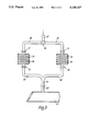
- FIGS. 2, 3, 4 and 5 schematically illustrate other metal vapour laser apparatus in accordance with the invention.
- a copper vapour laser apparatus includes a laser tube 1 having a quartz envelope 2 and end windows 3 and 4.
- An input port 5 of the laser 1 is connected to a reactor chamber 6 which is surrounded by a heater coil 7.
- the reactor chamber 6 includes a charge of solid copper in the form of granules 8 and has two input ports 9 and 10, one of which 9 admits buffer gas, in this case neon, and the other of which 10 permits halogen or halogen donor gas to be introduced into the chamber 6.
- buffer gas in this case neon
- halogen or halogen donor gas permits hydrogen bromide into the chamber via input port 10 and over the surfaces of the granules 8.
- the hydrogen bromide reacts with the copper at the surfaces of the granules 8 to give a layer of copper bromide.
- the heating effect of the coil 7 vaporises the copper bromide and it is drawn out of the reactor chamber 6 with the buffer gas to flow with the buffer gas along a duct 11 and via the input port 5 into the laser tube 1.
- the laser tube 1 includes electrodes 12 and 13 between which a discharge is established, causing the copper bromide to dissociate into copper and bromine. The resulting copper vapour is then excited by further discharges between the electrodes 12 and 13 to establish a population inversion and laser action.
- the laser tube 1 includes an output port 14 through which gases and vapour are exhausted from the tube and directed towards a suitable absorber.
- the apparatus may employ other suitable means for producing dissociation within the laser tube 1 and subsequent excitation of the metal vapour.
- the laser tube 15 is located in an oven 16 and includes electrodes 17 and 18 between which, in operation, a transverse discharge is established.
- the laser tube has an input port 19 and an output port 20.
- a cylindrical reactor chamber 21 is connected to the input port 19 via a connector 22 and is filled with a fine copper wire 23.
- a heater coil 24 surrounds the chamber 21.
- a mixture of chlorine and neon is directed along a conduit 25 which is connected to the chamber by a coupling 26.
- the chlorine passes through the chamber 21, causing copper chloride to be produced at the surface of the metal 23 within the chamber 21.
- the temperature of the reactor chamber 21 is kept sufficiently high that the copper chloride vaporises and enters the laser tube 15. Discharges are established between the electrodes 17 and 18 resulting in dissociation of the copper chloride to produce copper vapour, which then is further excited to form a lasing medium.
- the oven 16 surrounding the laser tube 15 reduces the condensation of metal on optical surfaces.
- the chamber 21 is removed by closing the couplings 22 and 26, enabling the gas-tight integrity of the laser tube 15 and input conduit 25 to be maintained. The residue left in the chamber 21 is removed and a fresh charge of metal wire inserted. The chamber 21 is then coupled back into the system and laser operation can recommence.
- FIG. 3 illustrates another laser apparatus in accordance with the invention schematically and in part.
- This apparatus is particularly suitable where it is important to be able to operate the laser substantially continuously without any stoppages.
- the arrangement includes an input conduit 27 which is connected to two branches 28 and 29 via a regulator and switch 30.
- the regulator 30 permits gases passed along input conduit 27 to be transmitted along either one branch or the other depending on its setting.
- the switch may be of a more complex nature to permit gas flowing through the input conduit 27 to be delivered to the branches in varying proportions. For example, it may be caused to flow in equal amounts between both branches or transmitted only along one branch.
- Each branch 28 and 29 is connected via couplings 31 and 32 to respective reactor chambers 33 and 34, each of which includes fine gold wire wool 35 and 36.
- the reactor chambers 33 and 34 have output ports coupled via couplings 37 and 38 to two output branches 39 and 40 respectively which combine into a single channel 41.
- the channel 41 is connected to an input port 42 of a laser tube 43.
- both reactor chambers 33 and 34 are charged with gold wire.
- the regulator and switch 30 is set such that any gas flowing through the input conduit 27 is directed along the left hand branch 28 as shown to the reactor chamber 33.
- a halogen donor gas and buffer gas are passed into the reaction chamber 33 via this route, in this particular arrangement the gases being a mixture of argon and chlorine.
- the reactor chamber is heated and causes gold chloride formed at the surface of the wire to be vaporised.
- the gold chloride flows along the output branch 39 of the reactor chamber and the common channel 41 to the laser tube 43.
- the gold chloride is dissociated and the resulting gold vapour is excited by discharge heating or in some other suitable manner to produce laser radiation.
- another embodiment of the invention includes a plurality of reactor chambers 44 to 47 each of which has its own input conduit 48 to 51 respectively and is filled with a metal gauze. The contents of the chambers are different in each case.
- the outputs of the reactor chambers 44 to 47 are connected to a common manifold 52 which in turn is connected via an input port 53 to laser tube 54.
- Halogen gases or halogen donor gases are applied to each of the input conduits 48 to 51 through respective valves 55 to 58 which are independently controlled by a processor 59 to be closed, partially open to a variable degree or fully open, depending on the amount of metal halide it is wished to produce within each chamber.
- a processor 59 By controlling the input of the gases to the various chambers, different laser wavelengths can be produced within the laser tube 46. For example, a combination of copper and gold halides may be formed.
- An arrangement such as the described with reference to FIG. 4 permits flexibility in the output of the laser to be achieved and has applications for example in the entertainment industry.
- FIG. 5 Another laser apparatus in accordance with the invention is illustrated schematically and in part in FIG. 5.
- This includes a laser tube 60 having an input port 61.
- the input port 61 is a copper tube and is surrounded by a heater coil 62.
- Bromine and a suitable buffer gas, such as neon, are passed through the input port 61 where copper bromide is formed on its inner surface.
- the heat produced by the coil 62 causes the copper bromide to vaporise and be drawn by the buffer gas flowing through the input port 61 into the laser tube 60.
- Electrodes within the laser tube 60 are arranged to provide discharge heating of the copper bromide to cause it to dissociate. The resulting copper vapour is then excited by further discharges between the electrodes.
Landscapes
- Physics & Mathematics (AREA)
- Electromagnetism (AREA)
- Engineering & Computer Science (AREA)
- Plasma & Fusion (AREA)
- Optics & Photonics (AREA)
- Lasers (AREA)
- Manufacture Of Electron Tubes, Discharge Lamp Vessels, Lead-In Wires, And The Like (AREA)
Abstract
Metal vapor laser apparatus includes a laser tube and a reactor chamber in which is contained metal which may be copper in the form of granules. Neon is introduced via one input port of the chamber and a halogen or halogen donor gas through another input port. A coil surrounds the reactor chamber and provides heating to its interior. The gas passes over the metal to form metal halide at its surface and is vaporized by the heating effects. The buffer gas and metal halide are then transmitted via a conduit into the laser tube where dissociation of the metal halide and subsequent excitation of metal vapor is carried out to produce laser radiation.
Description
This invention relates to metal vapour laser apparatus.
In one known type of metal vapour laser, solid metal is distributed along the length of a laser tube. The metal vapour used in the lasing process is produced by heating the solid metal, the vapour then being excited to obtain a population inversion and laser action. The operating temperatures of such lasers having copper vapour as the amplifying medium are typically around 1500° C. Considerable thermal insulation is required around the laser tube to maintain these conditions.
In another known type of metal vapour laser, the metal vapour which is used as the laser amplifying medium is derived from a metal halide compound. For example, copper vapour may be derived from copper bromide which is introduced into a laser tube and subsequently heated to cause it to vaporise and dissociate. The temperatures required for efficient operation of a metal halide laser are lower than those for metal vapour lasers in which the vapour is derived from solid metal charges, for example a laser employing copper bromide need be heated to only around 600° C. The amount of thermal insulation required is thus reduced and fast start up times may be achieved.
The present invention seeks to provide an improved metal vapour laser apparatus.
According to the invention, there is provided metal vapour laser apparatus comprising: means for passing a halogen or halogen donor gas over the surfaces of metal in a chamber to produce metal halide; a laser tube; means for introducing the metal halide into the laser tube from the chamber; and means for dissociating the metal halide to produce metal vapour for use in the laser process.
A halogen donor gas is a halogen compound, such as hydrogen bromide, which readily dissociates to give halogen molecules or ions. The metal is advantageously copper although other metals such as gold may be used. Only one metal or a mixture of metals may be employed depending on the wavelengths of laser radiation it is wished to generate. The halogen, or halogen donated, may be bromine, chlorine or some other suitable element from that group.
The metal may be contained within the chamber and in addition, or alternatively, may form surfaces of the chamber itself, in which case the chamber walls are of the metal or have a coating of the metal. The chamber may be located remote from the laser tube with a suitable connection between them or may open immediately into the laser tube. For example, the chamber may constituted by a conduit which also functions as an input port of the laser tube.
By employing the invention, it is possible to produce a high purity metal halide, enabling the laser tube to be operated at a high efficiency.
The laser tube may be of a simple design as it is not necessary to accommodate a solid metal or metal halide component within it prior to laser operation. As the laser is able to operate at relatively low temperatures, it may employ a quartz envelope and it does not require extensive thermal shielding. It may be desirable in some cases to provide an oven around the laser tube, or parts of it, to reduce condensation of metal on optical surfaces.
A further advantage of the invention is that the laser tube itself may be easily portable as it does not require the large amount of thermal insulation necessary where metal vapour is produced directly from solid metal.
A particularly significant advantage of laser apparatus in accordance with the invention is that the lifetime of the tube is enhanced due to the low temperature operating regime. Furthermore, the metal may be easily replenished in the chamber as there is no need to disturb the integrity of the laser tube in order to reload. Consequently, when the metal vapour source is exhausted, the down time during which reloading takes place can be greatly reduced from say, two or more hours to only a few minutes.
Preferably, heater means are included for heating the chamber to cause the metal halide to vaporise.
In one preferred embodiment of the invention, the apparatus includes two chambers for each of which means are included for flowing a halogen or halogen donor gas over metal surfaces to produce metal halide within it and means are provided for switching between the chambers such that metal halide is introduced from one or the other into the laser tube. Thus as the metal charge of one chamber nears exhaustion, the other chamber can be switched into use so as to produce metal halide for delivery to the laser tube. Whilst the second chamber is operative, the first may be recharged and this may completely eliminate the need to interrupt laser operation.
In another advantageous embodiment of the invention, a plurality of chambers is included which are controllable such that different ones or combinations are selectable for introducing metal halide into the laser tube. Thus, if the chambers include different metals the output spectrum of the laser tube may be controlled by selecting a chamber, or chambers, having a particular metal or combination of metals within it. In another embodiment, the chambers may each contain the same metal and be selected in turn, for example.
In those embodiments where a plurality of chambers is included, the halogen, or halogen donor, gas delivered to the chambers may be derived from the same source and directed either only to those chambers, which may be all of them, from which it is wished to obtain metal halide or to each chamber irrespective of whether or not a metal halide is to be introduced from that chamber. If the gas is directed to each chamber, valve means may be included after the chamber so that the metal halide may be delivered to the laser tube or to a dump, so as to control the introduction of the metal halides to the laser tube. In other embodiments the halogen gas or halogen donor gas may be derived from different sources and may be different elements or compounds.
It is preferred that the metal has an open configuration which presents a plurality of passages to gas flowing over its surfaces. For example, it could be in the form of a wire wool, a mesh or layers of grids, hence maximising the surface area available to the reaction with the halogen or halogen donor gas. Where the gas is caused to flow through a metal mesh, for example, the open aspect of the metal is chosen so as to present a relatively large surface area whilst not significantly impeding gas flow through the chamber.
Preferably, the chamber is connected to the laser tube via a coupling which enables it to be removed, for example for replenishment of the metal, without significantly altering the pressure within the laser tube.
A buffer gas, such as neon, may be fed with the halogen gas or halogen donor gas into the chamber or may be separately fed through the apparatus to the laser tube.
Some ways in which the invention may be performed are now described by way of example with reference to the accompanying drawings in which:
FIG. 1 schematically illustrates a laser apparatus in accordance with the invention; and
FIGS. 2, 3, 4 and 5 schematically illustrate other metal vapour laser apparatus in accordance with the invention.
With reference to FIG. 1, a copper vapour laser apparatus includes a laser tube 1 having a quartz envelope 2 and end windows 3 and 4. An input port 5 of the laser 1 is connected to a reactor chamber 6 which is surrounded by a heater coil 7. The reactor chamber 6 includes a charge of solid copper in the form of granules 8 and has two input ports 9 and 10, one of which 9 admits buffer gas, in this case neon, and the other of which 10 permits halogen or halogen donor gas to be introduced into the chamber 6. In this case, hydrogen bromide is conducted into the chamber via input port 10 and over the surfaces of the granules 8.
The hydrogen bromide reacts with the copper at the surfaces of the granules 8 to give a layer of copper bromide. The heating effect of the coil 7 vaporises the copper bromide and it is drawn out of the reactor chamber 6 with the buffer gas to flow with the buffer gas along a duct 11 and via the input port 5 into the laser tube 1.
In this embodiment of the invention, the laser tube 1 includes electrodes 12 and 13 between which a discharge is established, causing the copper bromide to dissociate into copper and bromine. The resulting copper vapour is then excited by further discharges between the electrodes 12 and 13 to establish a population inversion and laser action. The laser tube 1 includes an output port 14 through which gases and vapour are exhausted from the tube and directed towards a suitable absorber.
The apparatus may employ other suitable means for producing dissociation within the laser tube 1 and subsequent excitation of the metal vapour.
With reference to FIG. 2, in another laser apparatus in accordance with the invention, the laser tube 15 is located in an oven 16 and includes electrodes 17 and 18 between which, in operation, a transverse discharge is established. The laser tube has an input port 19 and an output port 20. A cylindrical reactor chamber 21 is connected to the input port 19 via a connector 22 and is filled with a fine copper wire 23. A heater coil 24 surrounds the chamber 21.
During operation of the laser apparatus, a mixture of chlorine and neon is directed along a conduit 25 which is connected to the chamber by a coupling 26. The chlorine passes through the chamber 21, causing copper chloride to be produced at the surface of the metal 23 within the chamber 21. The temperature of the reactor chamber 21 is kept sufficiently high that the copper chloride vaporises and enters the laser tube 15. Discharges are established between the electrodes 17 and 18 resulting in dissociation of the copper chloride to produce copper vapour, which then is further excited to form a lasing medium. The oven 16 surrounding the laser tube 15 reduces the condensation of metal on optical surfaces.
When the metal within the chamber 21 is substantially exhausted, such that only small amounts of metal halide are formed, the chamber 21 is removed by closing the couplings 22 and 26, enabling the gas-tight integrity of the laser tube 15 and input conduit 25 to be maintained. The residue left in the chamber 21 is removed and a fresh charge of metal wire inserted. The chamber 21 is then coupled back into the system and laser operation can recommence.
FIG. 3, illustrates another laser apparatus in accordance with the invention schematically and in part. This apparatus is particularly suitable where it is important to be able to operate the laser substantially continuously without any stoppages. The arrangement includes an input conduit 27 which is connected to two branches 28 and 29 via a regulator and switch 30. In this particular arrangement, the regulator 30 permits gases passed along input conduit 27 to be transmitted along either one branch or the other depending on its setting. In other arrangements the switch may be of a more complex nature to permit gas flowing through the input conduit 27 to be delivered to the branches in varying proportions. For example, it may be caused to flow in equal amounts between both branches or transmitted only along one branch. Each branch 28 and 29 is connected via couplings 31 and 32 to respective reactor chambers 33 and 34, each of which includes fine gold wire wool 35 and 36. The reactor chambers 33 and 34 have output ports coupled via couplings 37 and 38 to two output branches 39 and 40 respectively which combine into a single channel 41. The channel 41 is connected to an input port 42 of a laser tube 43.
During operation of the apparatus, both reactor chambers 33 and 34 are charged with gold wire. Initially, the regulator and switch 30 is set such that any gas flowing through the input conduit 27 is directed along the left hand branch 28 as shown to the reactor chamber 33. A halogen donor gas and buffer gas are passed into the reaction chamber 33 via this route, in this particular arrangement the gases being a mixture of argon and chlorine. The reactor chamber is heated and causes gold chloride formed at the surface of the wire to be vaporised. The gold chloride flows along the output branch 39 of the reactor chamber and the common channel 41 to the laser tube 43. The gold chloride is dissociated and the resulting gold vapour is excited by discharge heating or in some other suitable manner to produce laser radiation.
For a particular apparatus, it will be known what lifetime may be achieved using the amount of metal inserted within a reactor chamber. Towards the end of this lifetime, or at some other predetermined point, an operator changes the setting of the regulator and switch 30 so as to direct the gases flowing along the input duct 27 to the second reactor chamber 34 positioned on the right hand side of the apparatus as shown. This enables laser operation to be maintained with a minimal break in the delivery of gold chloride to the discharge region of the laser tube 43. Whilst the second reactor chamber 34 is providing the gold chloride for the reaction in the tube 43, the couplings on either side of the first reactor chamber 33 are closed and the chamber removed and refilled with gold wire. When the second reactor chamber 34 requires replenishment, the switch 30 is reset so as to redirect the gases to the first reactor chamber 33 once again.
With reference to FIG. 4, another embodiment of the invention includes a plurality of reactor chambers 44 to 47 each of which has its own input conduit 48 to 51 respectively and is filled with a metal gauze. The contents of the chambers are different in each case. The outputs of the reactor chambers 44 to 47 are connected to a common manifold 52 which in turn is connected via an input port 53 to laser tube 54. Halogen gases or halogen donor gases are applied to each of the input conduits 48 to 51 through respective valves 55 to 58 which are independently controlled by a processor 59 to be closed, partially open to a variable degree or fully open, depending on the amount of metal halide it is wished to produce within each chamber. By controlling the input of the gases to the various chambers, different laser wavelengths can be produced within the laser tube 46. For example, a combination of copper and gold halides may be formed.
An arrangement such as the described with reference to FIG. 4 permits flexibility in the output of the laser to be achieved and has applications for example in the entertainment industry.
Another laser apparatus in accordance with the invention is illustrated schematically and in part in FIG. 5. This includes a laser tube 60 having an input port 61. The input port 61 is a copper tube and is surrounded by a heater coil 62. Bromine and a suitable buffer gas, such as neon, are passed through the input port 61 where copper bromide is formed on its inner surface. The heat produced by the coil 62 causes the copper bromide to vaporise and be drawn by the buffer gas flowing through the input port 61 into the laser tube 60. Electrodes within the laser tube 60 are arranged to provide discharge heating of the copper bromide to cause it to dissociate. The resulting copper vapour is then excited by further discharges between the electrodes.
Claims (11)
1. Metal vapour laser apparatus comprising: a chamber; means for passing a halogen or halogen donor gas over the surfaces of metal in said chamber to produce metal halide; a laser tube; means for introducing said metal halide into said laser tube from said chamber; and means for dissociating said metal halide to produce metal vapour for use in the laser process.
2. Laser apparatus as claimed in claim 1 wherein said metal is contained within said chamber.
3. Laser apparatus as claimed in claim 1 wherein said metal forms surfaces of said chamber itself.
4. Laser apparatus as claimed in claim 1 wherein said chamber opens substantially directly into said laser tube.
5. Laser apparatus as claimed in claim 1 including coupling means between said chamber and said laser tube whereby the chamber is removable without substantially altering the pressure within said laser tube.
6. Laser apparatus as claimed in claim 1 including two chambers, for each of which means are included for flowing a halogen or halogen donor gas over metal surfaces to produce metal halide within it, and means for switching between said two chambers such that metal halide is selectably introduced from one or the other chamber into said laser tube.
7. Laser apparatus as claimed in claim 6 and including coupling means between each of said chambers and said laser tube whereby each chamber is removable without substantially altering the pressure within said laser tube.
8. Laser apparatus as claimed in claim 1 and including a plurality of chambers, for each of which means are included for flowing a halogen or halogen donor gas over metal surfaces to produce metal halide within it, and means for controlling said chambers such that different ones or combinations are selectable for introducing metal halide into said laser tube.
9. Laser apparatus as claimed in claim 8 wherein said means for controlling includes valve means associated with each chamber and means for adjusting the setting of said valve means to control the amount of metal halide delivered by each chamber to said laser tube.
10. Laser apparatus as claimed in claim 1 wherein said metal in said chamber has a configuration which presents a plurality of passages to gas flowing over its surfaces.
11. Laser apparatus as claimed in claim 10 wherein said metal is in the form of a wire wool or mesh.
Applications Claiming Priority (2)
| Application Number | Priority Date | Filing Date | Title |
|---|---|---|---|
| GB9216270 | 1992-07-30 | ||
| GB9216270A GB2269266B (en) | 1992-07-30 | 1992-07-30 | Metal vapour laser apparatus |
Publications (1)
| Publication Number | Publication Date |
|---|---|
| US5339327A true US5339327A (en) | 1994-08-16 |
Family
ID=10719590
Family Applications (1)
| Application Number | Title | Priority Date | Filing Date |
|---|---|---|---|
| US08/089,440 Expired - Fee Related US5339327A (en) | 1992-07-30 | 1993-07-12 | Metal vapor laser apparatus |
Country Status (10)
| Country | Link |
|---|---|
| US (1) | US5339327A (en) |
| EP (1) | EP0581453B1 (en) |
| JP (1) | JPH06164075A (en) |
| AU (1) | AU659331B2 (en) |
| CA (1) | CA2100128A1 (en) |
| DE (1) | DE69305930T2 (en) |
| GB (1) | GB2269266B (en) |
| IL (1) | IL106232A (en) |
| NO (1) | NO932698L (en) |
| RU (1) | RU2115204C1 (en) |
Cited By (1)
| Publication number | Priority date | Publication date | Assignee | Title |
|---|---|---|---|---|
| EP0783192A1 (en) | 1996-01-03 | 1997-07-09 | Commissariat A L'energie Atomique | Metal vapour laser device |
Families Citing this family (2)
| Publication number | Priority date | Publication date | Assignee | Title |
|---|---|---|---|---|
| AUPN813596A0 (en) * | 1996-02-16 | 1996-03-07 | Macquarie Research Limited | Metal vapour laser |
| RU2420844C2 (en) * | 2009-01-19 | 2011-06-10 | Учреждение Российской академии наук Институт оптики атмосферы им.В.И.Зуева Сибирского отделения РАН (ИОА СО РАН) | Metal halide vapour laser active element |
Citations (8)
| Publication number | Priority date | Publication date | Assignee | Title |
|---|---|---|---|---|
| US4328464A (en) * | 1980-02-07 | 1982-05-04 | Nasa | High power metallic halide laser |
| US4347613A (en) * | 1980-03-14 | 1982-08-31 | Nasa | Method and apparatus for convection control of metallic halide vapor density in a metallic halide laser |
| US4434492A (en) * | 1981-03-10 | 1984-02-28 | The United States Of America As Represented By The Secretary Of The Air Force | Method and apparatus for iodine vaporization |
| US4951297A (en) * | 1989-01-12 | 1990-08-21 | Georgia Tech Research Corporation | Chemical process yielding stimulated emission of visible radiation via fast near resonant energy transfer |
| US4955033A (en) * | 1988-05-24 | 1990-09-04 | Eev Limited | Metal vapor laser apparatus |
| US4958356A (en) * | 1988-10-04 | 1990-09-18 | Fuji Electric Co., Ltd. | Excimer laser apparatus |
| US5005181A (en) * | 1988-10-20 | 1991-04-02 | Mitsubishi Denki K.K. | Method for controlling gas in halogen gas laser and device therefor |
| US5220574A (en) * | 1990-11-20 | 1993-06-15 | Lambda Physik Gesellschaft Zur Herstellung Von Lasern Mbh | Excimer laser with hydrogen chloride and method for producing hydrogen chloride for an excimer laser |
Family Cites Families (1)
| Publication number | Priority date | Publication date | Assignee | Title |
|---|---|---|---|---|
| US4232274A (en) * | 1978-05-30 | 1980-11-04 | Kimmon Electric Co., Ltd. | Metal vapor laser system |
-
1992
- 1992-07-30 GB GB9216270A patent/GB2269266B/en not_active Expired - Fee Related
-
1993
- 1993-07-02 EP EP93305228A patent/EP0581453B1/en not_active Expired - Lifetime
- 1993-07-02 DE DE69305930T patent/DE69305930T2/en not_active Expired - Fee Related
- 1993-07-05 IL IL10623293A patent/IL106232A/en not_active IP Right Cessation
- 1993-07-08 CA CA002100128A patent/CA2100128A1/en not_active Abandoned
- 1993-07-12 US US08/089,440 patent/US5339327A/en not_active Expired - Fee Related
- 1993-07-27 NO NO932698A patent/NO932698L/en unknown
- 1993-07-29 RU RU93049324A patent/RU2115204C1/en active
- 1993-07-29 AU AU44248/93A patent/AU659331B2/en not_active Ceased
- 1993-07-30 JP JP5189948A patent/JPH06164075A/en not_active Withdrawn
Patent Citations (8)
| Publication number | Priority date | Publication date | Assignee | Title |
|---|---|---|---|---|
| US4328464A (en) * | 1980-02-07 | 1982-05-04 | Nasa | High power metallic halide laser |
| US4347613A (en) * | 1980-03-14 | 1982-08-31 | Nasa | Method and apparatus for convection control of metallic halide vapor density in a metallic halide laser |
| US4434492A (en) * | 1981-03-10 | 1984-02-28 | The United States Of America As Represented By The Secretary Of The Air Force | Method and apparatus for iodine vaporization |
| US4955033A (en) * | 1988-05-24 | 1990-09-04 | Eev Limited | Metal vapor laser apparatus |
| US4958356A (en) * | 1988-10-04 | 1990-09-18 | Fuji Electric Co., Ltd. | Excimer laser apparatus |
| US5005181A (en) * | 1988-10-20 | 1991-04-02 | Mitsubishi Denki K.K. | Method for controlling gas in halogen gas laser and device therefor |
| US4951297A (en) * | 1989-01-12 | 1990-08-21 | Georgia Tech Research Corporation | Chemical process yielding stimulated emission of visible radiation via fast near resonant energy transfer |
| US5220574A (en) * | 1990-11-20 | 1993-06-15 | Lambda Physik Gesellschaft Zur Herstellung Von Lasern Mbh | Excimer laser with hydrogen chloride and method for producing hydrogen chloride for an excimer laser |
Cited By (2)
| Publication number | Priority date | Publication date | Assignee | Title |
|---|---|---|---|---|
| EP0783192A1 (en) | 1996-01-03 | 1997-07-09 | Commissariat A L'energie Atomique | Metal vapour laser device |
| US5898723A (en) * | 1996-01-03 | 1999-04-27 | Commissariat A L'energie Atomique | Metal vapor laser device |
Also Published As
| Publication number | Publication date |
|---|---|
| IL106232A (en) | 1996-08-04 |
| IL106232A0 (en) | 1993-11-15 |
| NO932698L (en) | 1994-01-31 |
| GB9216270D0 (en) | 1992-09-09 |
| AU4424893A (en) | 1994-02-03 |
| NO932698D0 (en) | 1993-07-27 |
| DE69305930D1 (en) | 1996-12-19 |
| AU659331B2 (en) | 1995-05-11 |
| GB2269266B (en) | 1995-11-22 |
| GB2269266A (en) | 1994-02-02 |
| RU2115204C1 (en) | 1998-07-10 |
| DE69305930T2 (en) | 1997-03-13 |
| CA2100128A1 (en) | 1994-01-31 |
| EP0581453B1 (en) | 1996-11-13 |
| EP0581453A1 (en) | 1994-02-02 |
| JPH06164075A (en) | 1994-06-10 |
Similar Documents
| Publication | Publication Date | Title |
|---|---|---|
| US5977552A (en) | Boron ion sources for ion implantation apparatus | |
| US4830702A (en) | Hollow cathode plasma assisted apparatus and method of diamond synthesis | |
| US4641060A (en) | Method and apparatus using electron cyclotron heated plasma for vacuum pumping | |
| US9334855B1 (en) | Hall thruster for use with a condensable propellant | |
| US5339327A (en) | Metal vapor laser apparatus | |
| US4641313A (en) | Room temperature metal vapour laser | |
| JPS62283840A (en) | Method and apparatus for manufacturing doped optical preform | |
| JP2007087939A (en) | Extreme ultraviolet radiation source with high radiation output based on gas discharge | |
| US5159173A (en) | Apparatus for reducing plasma constriction by intermediate injection of hydrogen in RF plasma gun | |
| EP0343795B1 (en) | Metal vapour laser device | |
| US3510797A (en) | Acetylene flame laser | |
| US7518124B2 (en) | Monatomic dopant ion source and method | |
| US2786156A (en) | Corpuscular beam apparatus | |
| JP2003346672A (en) | Ion source and driving method thereof | |
| US6497744B2 (en) | Apparatus and method for generating indium ion beam | |
| US3811095A (en) | Electric-discharge excited gaseous laser | |
| JP3164662B2 (en) | Material gas supply pipe heating device | |
| US4680008A (en) | High temperature furnace for integrated circuit manufacture | |
| US4584689A (en) | Apparatus for modifying the liquefication or solidification point of a gas | |
| US12407423B2 (en) | Quantum optical communication using photon transmission from a vacuum chamber | |
| US4327338A (en) | Nuclear activated cw chemical laser | |
| US4559466A (en) | Metal vapor segmented discharge tubes | |
| JPH06124672A (en) | Material vaporizer | |
| US4201950A (en) | Low deactivation chemical laser | |
| JPH10242054A (en) | Film forming equipment |
Legal Events
| Date | Code | Title | Description |
|---|---|---|---|
| AS | Assignment |
Owner name: EEV LIMITED Free format text: ASSIGNMENT OF ASSIGNORS INTEREST;ASSIGNORS:LIVINGSTONE, EWAN SUTHERLAND;CLARK, GRAEME LAWRENCE;REEL/FRAME:006630/0315 Effective date: 19930623 |
|
| FEPP | Fee payment procedure |
Free format text: PAYOR NUMBER ASSIGNED (ORIGINAL EVENT CODE: ASPN); ENTITY STATUS OF PATENT OWNER: LARGE ENTITY |
|
| FPAY | Fee payment |
Year of fee payment: 4 |
|
| REMI | Maintenance fee reminder mailed | ||
| LAPS | Lapse for failure to pay maintenance fees | ||
| STCH | Information on status: patent discontinuation |
Free format text: PATENT EXPIRED DUE TO NONPAYMENT OF MAINTENANCE FEES UNDER 37 CFR 1.362 |
|
| FP | Lapsed due to failure to pay maintenance fee |
Effective date: 20020816 |